clock FORD SIERRA 1983 1.G Routine Manintenance And Servicing Workshop Manual
[x] Cancel search | Manufacturer: FORD, Model Year: 1983, Model line: SIERRA, Model: FORD SIERRA 1983 1.GPages: 22, PDF Size: 1.26 MB
Page 13 of 22

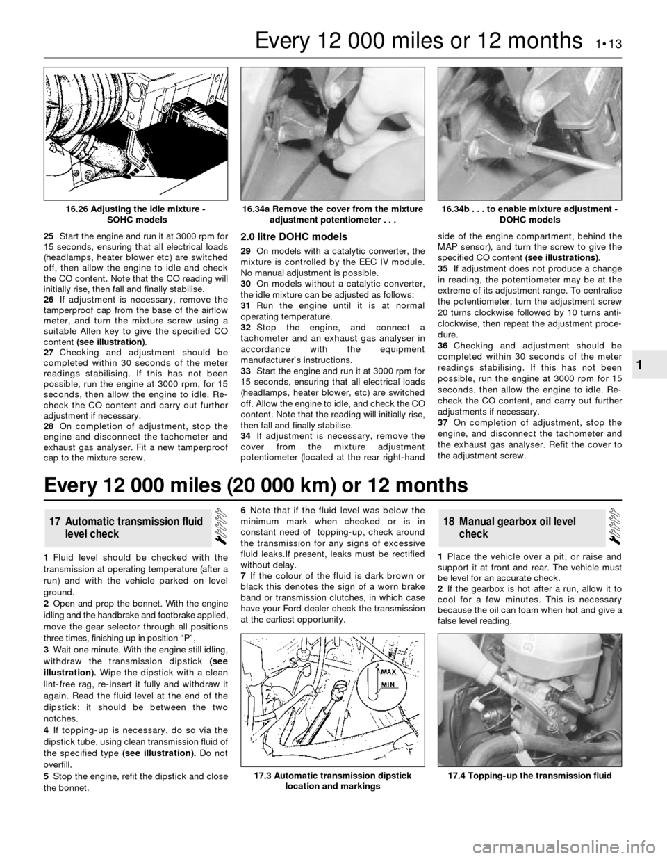
25Start the engine and run it at 3000 rpm for
15 seconds, ensuring that all electrical loads
(headlamps, heater blower etc) are switched
off, then allow the engine to idle and check
the CO content. Note that the CO reading will
initially rise, then fall and finally stabilise.
26If adjustment is necessary, remove the
tamperproof cap from the base of the airflow
meter, and turn the mixture screw using a
suitable Allen key to give the specified CO
content (see illustration).
27Checking and adjustment should be
completed within 30 seconds of the meter
readings stabilising. If this has not been
possible, run the engine at 3000 rpm, for 15
seconds, then allow the engine to idle. Re-
check the CO content and carry out further
adjustment if necessary.
28On completion of adjustment, stop the
engine and disconnect the tachometer and
exhaust gas analyser. Fit a new tamperproof
cap to the mixture screw.2.0 litre DOHC models
29On models with a catalytic converter, the
mixture is controlled by the EEC IV module.
No manual adjustment is possible.
30On models without a catalytic converter,
the idle mixture can be adjusted as follows:
31Run the engine until it is at normal
operating temperature.
32Stop the engine, and connect a
tachometer and an exhaust gas analyser in
accordance with the equipment
manufacturer’s instructions.
33Start the engine and run it at 3000 rpm for
15 seconds, ensuring that all electrical loads
(headlamps, heater blower, etc) are switched
off. Allow the engine to idle, and check the CO
content. Note that the reading will initially rise,
then fall and finally stabilise.
34If adjustment is necessary, remove the
cover from the mixture adjustment
potentiometer (located at the rear right-handside of the engine compartment, behind the
MAP sensor), and turn the screw to give the
specified CO content (see illustrations).
35If adjustment does not produce a change
in reading, the potentiometer may be at the
extreme of its adjustment range. To centralise
the potentiometer, turn the adjustment screw
20 turns clockwise followed by 10 turns anti-
clockwise, then repeat the adjustment proce-
dure.
36Checking and adjustment should be
completed within 30 seconds of the meter
readings stabilising. If this has not been
possible, run the engine at 3000 rpm for 15
seconds, then allow the engine to idle. Re-
check the CO content, and carry out further
adjustments if necessary.
37On completion of adjustment, stop the
engine, and disconnect the tachometer and
the exhaust gas analyser. Refit the cover to
the adjustment screw.
1Fluid level should be checked with the
transmission at operating temperature (after a
run) and with the vehicle parked on level
ground.
2Open and prop the bonnet. With the engine
idling and the handbrake and footbrake applied,
move the gear selector through all positions
three times, finishing up in position “P”,
3Wait one minute. With the engine still idling,
withdraw the transmission dipstick (see
illustration).Wipe the dipstick with a clean
lint-free rag, re-insert it fully and withdraw it
again. Read the fluid level at the end of the
dipstick: it should be between the two
notches.
4If topping-up is necessary, do so via the
dipstick tube, using clean transmission fluid of
the specified type (see illustration).Do not
overfill.
5Stop the engine, refit the dipstick and close
the bonnet.6Note that if the fluid level was below the
minimum mark when checked or is in
constant need of topping-up, check around
the transmission for any signs of excessive
fluid leaks.If present, leaks must be rectified
without delay.
7If the colour of the fluid is dark brown or
black this denotes the sign of a worn brake
band or transmission clutches, in which case
have your Ford dealer check the transmission
at the earliest opportunity.1Place the vehicle over a pit, or raise and
support it at front and rear. The vehicle must
be level for an accurate check.
2If the gearbox is hot after a run, allow it to
cool for a few minutes. This is necessary
because the oil can foam when hot and give a
false level reading.
18Manual gearbox oil level
check17Automatic transmission fluid
level check
Every 12 000 miles or 12 months 1•13
1
16.34b . . . to enable mixture adjustment -
DOHC models
17.4 Topping-up the transmission fluid17.3 Automatic transmission dipstick
location and markings
16.34a Remove the cover from the mixture
adjustment potentiometer . . .16.26 Adjusting the idle mixture -
SOHC models
Every 12 000 miles (20 000 km) or 12 months
Page 15 of 22

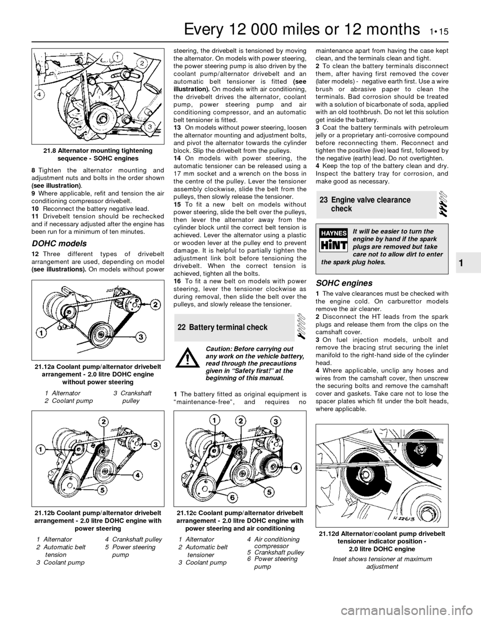
8Tighten the alternator mounting and
adjustment nuts and bolts in the order shown
(see illustration).
9Where applicable, refit and tension the air
conditioning compressor drivebelt.
10Reconnect the battery negative lead.
11Drivebelt tension should be rechecked
and if necessary adjusted after the engine has
been run for a minimum of ten minutes.
DOHC models
12Three different types of drivebelt
arrangement are used, depending on model
(see illustrations).On models without powersteering, the drivebelt is tensioned by moving
the alternator. On models with power steering,
the power steering pump is also driven by the
coolant pump/alternator drivebelt and an
automatic belt tensioner is fitted (see
illustration).On models with air conditioning,
the drivebelt drives the alternator, coolant
pump, power steering pump and air
conditioning compressor, and an automatic
belt tensioner is fitted.
13On models without power steering, loosen
the alternator mounting and adjustment bolts,
and pivot the alternator towards the cylinder
block. Slip the drivebelt from the pulleys.
14On models with power steering, the
automatic tensioner can be released using a
17 mm socket and a wrench on the boss in
the centre of the pulley. Lever the tensioner
assembly clockwise, slide the belt from the
pulleys, then slowly release the tensioner.
15To fit a new belt on models without
power steering, slide the belt over the pulleys,
then lever the alternator away from the
cylinder block until the correct belt tension is
achieved. Lever the alternator using a plastic
or wooden lever at the pulley end to prevent
damage. It is helpful to partially tighten the
adjustment link bolt before tensioning the
drivebelt. When the correct tension is
achieved, tighten all the bolts.
16To fit a new belt on models with power
steering, lever the tensioner clockwise as
during removal, then slide the belt over the
pulleys, and slowly release the tensioner.
1The battery fitted as original equipment is
“maintenance-free”, and requires nomaintenance apart from having the case kept
clean, and the terminals clean and tight.
2To clean the battery terminals disconnect
them, after having first removed the cover
(later models) - negative earth first. Use a wire
brush or abrasive paper to clean the
terminals. Bad corrosion should be treated
with a solution of bicarbonate of soda, applied
with an old toothbrush. Do not let this solution
get inside the battery.
3Coat the battery terminals with petroleum
jelly or a proprietary anti-corrosive compound
before reconnecting them. Reconnect and
tighten the positive (live) lead first, followed by
the negative (earth) lead. Do not overtighten.
4Keep the top of the battery clean and dry.
Inspect the battery tray for corrosion, and
make good as necessary.
SOHC engines
1The valve clearances must be checked with
the engine cold. On carburettor models
remove the air cleaner.
2Disconnect the HT leads from the spark
plugs and release them from the clips on the
camshaft cover.
3On fuel injection models, unbolt and
remove the bracing strut securing the inlet
manifold to the right-hand side of the cylinder
head.
4Where applicable, unclip any hoses and
wires from the camshaft cover, then unscrew
the securing bolts and remove the camshaft
cover and gaskets. Take care not to lose the
spacer plates which fit under the bolt heads,
where applicable.
23Engine valve clearance
check
22Battery terminal check
Every 12 000 miles or 12 months 1•15
1
21.12b Coolant pump/alternator drivebelt
arrangement - 2.0 litre DOHC engine with
power steering
1 Alternator
2 Automatic belt
tension
3 Coolant pump4 Crankshaft pulley
5 Power steering
pump21.12d Alternator/coolant pump drivebelt
tensioner indicator position -
2.0 litre DOHC engine
Inset shows tensioner at maximum
adjustment
1 Alternator
2 Automatic belt
tensioner
3 Coolant pump4 Air conditioning
compressor
5 Crankshaft pulley
6 Power steering
pump
21.12c Coolant pump/alternator drivebelt
arrangement - 2.0 litre DOHC engine with
power steering and air conditioning
21.12a Coolant pump/alternator drivebelt
arrangement - 2.0 litre DOHC engine
without power steering
1 Alternator
2 Coolant pump3 Crankshaft
pulley
21.8 Alternator mounting tightening
sequence - SOHC engines
Caution: Before carrying out
any work on the vehicle battery,
read through the precautions
given in “Safety first!” at the
beginning of this manual.
It will be easier to turn the
engine by hand if the spark
plugs are removed but take
care not to allow dirt to enter
the spark plug holes.
Page 16 of 22

5Numbering from the front (camshaft
sprocket) end of the engine, the exhaust
valves are 1, 3, 5 and 7, and the inlet valves
are 2, 4, 6 and 8.
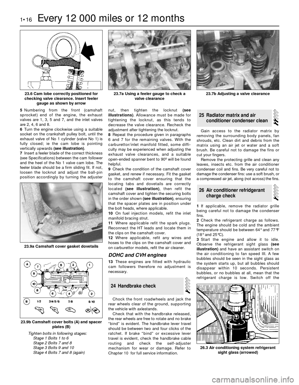
6Turn the engine clockwise using a suitable
socket on the crankshaft pulley bolt, until the
exhaust valve of No 1 cylinder (valve No 1) is
fully closed; ie the cam lobe is pointing
vertically upwards (see illustration).
7Insert a feeler blade of the correct thickness
(see Specifications) between the cam follower
and the heel of the No 1 valve cam lobe. The
feeler blade should be a firm sliding fit. If not,
loosen the locknut and adjust the ball-pin
position accordingly by turning the adjusternut, then tighten the locknut (see
illustrations). Allowance must be made for
tightening the locknut, as this tends to
decrease the valve clearance. Recheck the
adjustment after tightening the locknut.
8Repeat the procedure given in paragraphs
6 and 7 for the remaining valves. With the
carburettor/inlet manifold fitted, some diffi-
culty may be experienced when adjusting the
exhaust valve clearances, and a suitable
open-ended spanner bent to 90º will be found
helpful.
9Check the condition of the camshaft cover
gasket, and renew if necessary. Fit the gasket
to the camshaft cover ensuring that the
locating tabs and dovetails are correctly
located (see illustration), then refit the
camshaft cover and tighten the securing bolts
in the order shown (see illustration), ensuring
that the spacer plates are in position under
the bolt heads, where applicable.
10On fuel injection models, refit the inlet
manifold bracing strut.
11Where applicable refit the spark plugs.
Reconnect the HT leads and locate them in
the clips on the camshaft cover.
12Where applicable, refit any wires and
hoses to the clips on the camshaft cover and
on carburettor models, refit the air cleaner.
DOHCand CVH engines
13These engines are fitted with hydraulic
cam followers therefore no adjustment is
necessary.
Chock the front roadwheels and jack the
rear wheels clear of the ground, supporting
the vehicle with axlestands.
Check that with the handbrake released,
the rear wheels are free to rotate and no brake
“bind” is evident. The handbrake lever travel
should be between two and four clicks of the
ratchet. If brake “bind” or excessive lever
travel is evident, check the handbrake cable
routing and check the self-adjuster
mechanism for wear or damage. Refer to
Chapter 10 for full service information. Gain access to the radiator matrix by
removing the surrounding body panels, fan
shrouds, etc. Clean dirt and debris from the
matrix using an air jet or water and a soft
brush. Be careful not to damage the fins or
cut your fingers.
Remove the protecting grille and clean any
leaves, insects etc. from the air conditioner
condenser coil and fins. Be very careful not to
damage the condenser fins: use a soft brush, or
a compressed air jet, along (not across) the fins.
1If applicable, remove the radiator grille
being careful not to damage the condenser
fins.
2Check the refrigerant charge as follows.
The engine should be cold and the ambient
temperature should be between 64°and 77°F
(18°and 25°C).
3Start the engine and allow it to idle.
Observe the refrigerant sight glass(see
illustration)and have an assistant switch on
the air conditioning to fan speed III. A few
bubbles should be seen in the sight glass as
the system starts up, but all bubbles should
disappear within 10 seconds. Persistent
bubbles, or no bubbles at all, mean that the
refrigerant charge is low. Switch off the
26Air conditioner refridgerant
charge check
25Radiator matrix and air
conditioner condenser clean
24Handbrake check
1•16Every 12 000 miles or 12 months
23.6 Cam lobe correctly positioned for
checking valve clearance. Insert feeler
gauge as shown by arrow23.7b Adjusting a valve clearance
26.3 Air conditioning system refrigerant
sight glass (arrowed)
23.9b Camshaft cover bolts (A) and spacer
plates (B)
Tighten bolts in following stages:
Stage 1 Bolts 1 to 6
Stage 2 Bolts 7 and 8
Stage 3 Bolts 9 and 10
Stage 4 Bolts 7 and 8 (again)
23.9a Camshaft cover gasket dovetails
23.7a Using a feeler gauge to check a
valve clearance