seat FORD SIERRA 1984 1.G Reference Workshop Manual
[x] Cancel search | Manufacturer: FORD, Model Year: 1984, Model line: SIERRA, Model: FORD SIERRA 1984 1.GPages: 26, PDF Size: 0.57 MB
Page 7 of 26
MOT test checksREF•7
REF
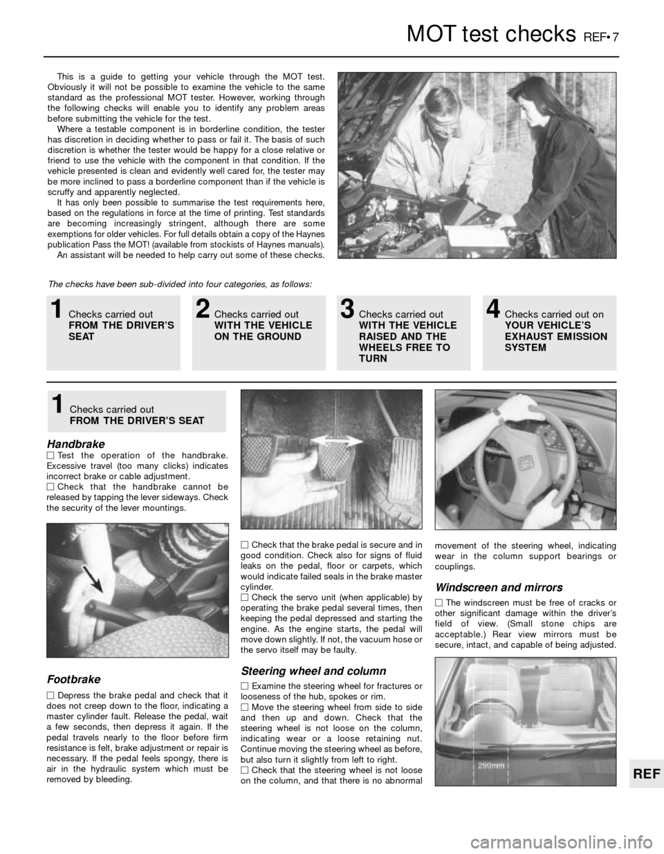
This is a guide to getting your vehicle through the MOT test.
Obviously it will not be possible to examine the vehicle to the same
standard as the professional MOT tester. However, working through
the following checks will enable you to identify any problem areas
before submitting the vehicle for the test.
Where a testable component is in borderline condition, the tester
has discretion in deciding whether to pass or fail it. The basis of such
discretion is whether the tester would be happy for a close relative or
friend to use the vehicle with the component in that condition. If the
vehicle presented is clean and evidently well cared for, the tester may
be more inclined to pass a borderline component than if the vehicle is
scruffy and apparently neglected.
It has only been possible to summarise the test requirements here,
based on the regulations in force at the time of printing. Test standards
are becoming increasingly stringent, although there are some
exemptions for older vehicles. For full details obtain a copy of the Haynes
publication Pass the MOT! (available from stockists of Haynes manuals).
An assistant will be needed to help carry out some of these checks.
The checks have been sub-divided into four categories, as follows:
HandbrakeMTest the operation of the handbrake.
Excessive travel (too many clicks) indicates
incorrect brake or cable adjustment.
MCheck that the handbrake cannot be
released by tapping the lever sideways. Check
the security of the lever mountings.
Footbrake
MDepress the brake pedal and check that it
does not creep down to the floor, indicating a
master cylinder fault. Release the pedal, wait
a few seconds, then depress it again. If the
pedal travels nearly to the floor before firm
resistance is felt, brake adjustment or repair is
necessary. If the pedal feels spongy, there is
air in the hydraulic system which must be
removed by bleeding.MCheck that the brake pedal is secure and in
good condition. Check also for signs of fluid
leaks on the pedal, floor or carpets, which
would indicate failed seals in the brake master
cylinder.
MCheck the servo unit (when applicable) by
operating the brake pedal several times, then
keeping the pedal depressed and starting the
engine. As the engine starts, the pedal will
move down slightly. If not, the vacuum hose or
the servo itself may be faulty.
Steering wheel and column
MExamine the steering wheel for fractures or
looseness of the hub, spokes or rim.
MMove the steering wheel from side to side
and then up and down. Check that the
steering wheel is not loose on the column,
indicating wear or a loose retaining nut.
Continue moving the steering wheel as before,
but also turn it slightly from left to right.
MCheck that the steering wheel is not loose
on the column, and that there is no abnormalmovement of the steering wheel, indicating
wear in the column support bearings or
couplings.
Windscreen and mirrors
MThe windscreen must be free of cracks or
other significant damage within the driver’s
field of view. (Small stone chips are
acceptable.) Rear view mirrors must be
secure, intact, and capable of being adjusted.
1Checks carried out
FROM THE DRIVER’S SEAT
1Checks carried out
FROM THE DRIVER’S
SEAT2Checks carried out
WITH THE VEHICLE
ON THE GROUND3Checks carried out
WITH THE VEHICLE
RAISED AND THE
WHEELS FREE TO
TURN4Checks carried out on
YOUR VEHICLE’S
EXHAUST EMISSION
SYSTEM
Page 8 of 26
REF•8MOTtest checks
Seat belts and seats
Note: The following checks are applicable to
all seat belts, front and rear.
MExamine the webbing of all the belts
(including rear belts if fitted) for cuts, serious
fraying or deterioration. Fasten and unfasten
each belt to check the buckles. If applicable,
check the retracting mechanism. Check the
security of all seat belt mountings accessible
from inside the vehicle.
MThe front seats themselves must be
securely attached and the backrests must
lock in the upright position.
Doors
MBoth front doors must be able to be opened
and closed from outside and inside, and must
latch securely when closed.
Vehicle identification
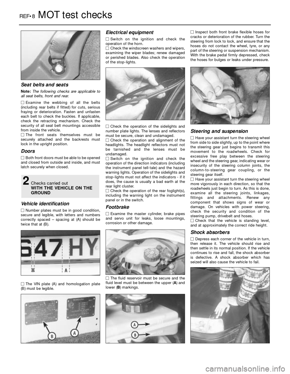
MNumber plates must be in good condition,
secure and legible, with letters and numbers
correctly spaced – spacing at (A) should be
twice that at (B).
MThe VIN plate (A) and homologation plate
(B) must be legible.
Electrical equipment
MSwitch on the ignition and check the
operation of the horn.
MCheck the windscreen washers and wipers,
examining the wiper blades; renew damaged
or perished blades. Also check the operation
of the stop-lights.
MCheck the operation of the sidelights and
number plate lights. The lenses and reflectors
must be secure, clean and undamaged.
MCheck the operation and alignment of the
headlights. The headlight reflectors must not
be tarnished and the lenses must be
undamaged.
MSwitch on the ignition and check the
operation of the direction indicators (including
the instrument panel tell-tale) and the hazard
warning lights. Operation of the sidelights and
stop-lights must not affect the indicators - if it
does, the cause is usually a bad earth at the
rear light cluster.
MCheck the operation of the rear foglight(s),
including the warning light on the instrument
panel or in the switch.
Footbrake
MExamine the master cylinder, brake pipes
and servo unit for leaks, loose mountings,
corrosion or other damage.
MThe fluid reservoir must be secure and the
fluid level must be between the upper (A) and
lower (B) markings.MInspect both front brake flexible hoses for
cracks or deterioration of the rubber. Turn the
steering from lock to lock, and ensure that the
hoses do not contact the wheel, tyre, or any
part of the steering or suspension mechanism.
With the brake pedal firmly depressed, check
the hoses for bulges or leaks under pressure.
Steering and suspension
MHave your assistant turn the steering wheel
from side to side slightly, up to the point where
the steering gear just begins to transmit this
movement to the roadwheels. Check for
excessive free play between the steering
wheel and the steering gear, indicating wear or
insecurity of the steering column joints, the
column-to-steering gear coupling, or the
steering gear itself.
MHave your assistant turn the steering wheel
more vigorously in each direction, so that the
roadwheels just begin to turn. As this is done,
examine all the steering joints, linkages,
fittings and attachments. Renew any
component that shows signs of wear or
damage. On vehicles with power steering,
check the security and condition of the
steering pump, drivebelt and hoses.
MCheck that the vehicle is standing level,
and at approximately the correct ride height.
Shock absorbers
MDepress each corner of the vehicle in turn,
then release it. The vehicle should rise and
then settle in its normal position. If the vehicle
continues to rise and fall, the shock absorber
is defective. A shock absorber which has
seized will also cause the vehicle to fail.
2Checks carried out
WITH THE VEHICLE ON THE
GROUND
Page 9 of 26
MOTtest checksREF•9
REF
Exhaust system
MStart the engine. With your assistant
holding a rag over the tailpipe, check the
entire system for leaks. Repair or renew
leaking sections.
Jack up the front and rear of the vehicle,
and securely support it on axle stands.
Position the stands clear of the suspension
assemblies. Ensure that the wheels are
clear of the ground and that the steering
can be turned from lock to lock.
Steering mechanism
MHave your assistant turn the steering from
lock to lock. Check that the steering turns
smoothly, and that no part of the steering
mechanism, including a wheel or tyre, fouls
any brake hose or pipe or any part of the body
structure.
MExamine the steering rack rubber gaiters
for damage or insecurity of the retaining clips.
If power steering is fitted, check for signs of
damage or leakage of the fluid hoses, pipes or
connections. Also check for excessive
stiffness or binding of the steering, a missing
split pin or locking device, or severe corrosion
of the body structure within 30 cm of any
steering component attachment point.
Front and rear suspension and
wheel bearings
MStarting at the front right-hand side, grasp
the roadwheel at the 3 o’clock and 9 o’clock
positions and shake it vigorously. Check for
free play or insecurity at the wheel bearings,
suspension balljoints, or suspension mount-
ings, pivots and attachments.
MNow grasp the wheel at the 12 o’clock and
6 o’clock positions and repeat the previous
inspection. Spin the wheel, and check for
roughness or tightness of the front wheel
bearing.
MIf excess free play is suspected at a
component pivot point, this can be confirmed
by using a large screwdriver or similar tool and
levering between the mounting and the
component attachment. This will confirm
whether the wear is in the pivot bush, its
retaining bolt, or in the mounting itself (the bolt
holes can often become elongated).
MCarry out all the above checks at the other
front wheel, and then at both rear wheels.
Springs and shock absorbers
MExamine the suspension struts (when
applicable) for serious fluid leakage, corrosion,
or damage to the casing. Also check the
security of the mounting points.
MIf coil springs are fitted, check that the
spring ends locate in their seats, and that the
spring is not corroded, cracked or broken.
MIf leaf springs are fitted, check that all
leaves are intact, that the axle is securely
attached to each spring, and that there is no
deterioration of the spring eye mountings,
bushes, and shackles.MThe same general checks apply to vehicles
fitted with other suspension types, such as
torsion bars, hydraulic displacer units, etc.
Ensure that all mountings and attachments are
secure, that there are no signs of excessive
wear, corrosion or damage, and (on hydraulic
types) that there are no fluid leaks or damaged
pipes.
MInspect the shock absorbers for signs of
serious fluid leakage. Check for wear of the
mounting bushes or attachments, or damage
to the body of the unit.
Driveshafts
(fwd vehicles only)
MRotate each front wheel in turn and inspect
the constant velocity joint gaiters for splits or
damage. Also check that each driveshaft is
straight and undamaged.
Braking system
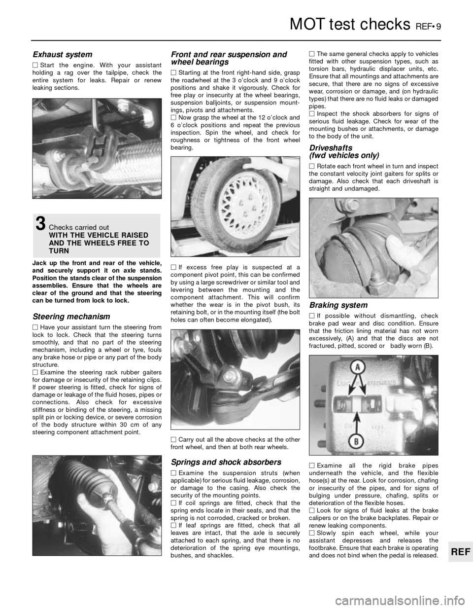
MIf possible without dismantling, check
brake pad wear and disc condition. Ensure
that the friction lining material has not worn
excessively, (A) and that the discs are not
fractured, pitted, scored or badly worn (B).
MExamine all the rigid brake pipes
underneath the vehicle, and the flexible
hose(s) at the rear. Look for corrosion, chafing
or insecurity of the pipes, and for signs of
bulging under pressure, chafing, splits or
deterioration of the flexible hoses.
MLook for signs of fluid leaks at the brake
calipers or on the brake backplates. Repair or
renew leaking components.
MSlowly spin each wheel, while your
assistant depresses and releases the
footbrake. Ensure that each brake is operating
and does not bind when the pedal is released.
3Checks carried out
WITH THE VEHICLE RAISED
AND THE WHEELS FREE TO
TURN
Page 10 of 26
REF•10MOTtest checks
MExamine the handbrake mechanism,
checking for frayed or broken cables,
excessive corrosion, or wear or insecurity of
the linkage. Check that the mechanism works
on each relevant wheel, and releases fully,
without binding.
MIt is not possible to test brake efficiency
without special equipment, but a road test
can be carried out later to check that the
vehicle pulls up in a straight line.
Fuel and exhaust systems
MInspect the fuel tank (including the filler
cap), fuel pipes, hoses and unions. All
components must be secure and free from
leaks.
MExamine the exhaust system over its entire
length, checking for any damaged, broken or
missing mountings, security of the retaining
clamps and rust or corrosion.
Wheels and tyres
MExamine the sidewalls and tread area of
each tyre in turn. Check for cuts, tears, lumps,
bulges, separation of the tread, and exposure
of the ply or cord due to wear or damage.
Check that the tyre bead is correctly seated
on the wheel rim, that the valve is sound andproperly seated, and that the wheel is not
distorted or damaged.
MCheck that the tyres are of the correct size
for the vehicle, that they are of the same size
and type on each axle, and that the pressures
are correct.
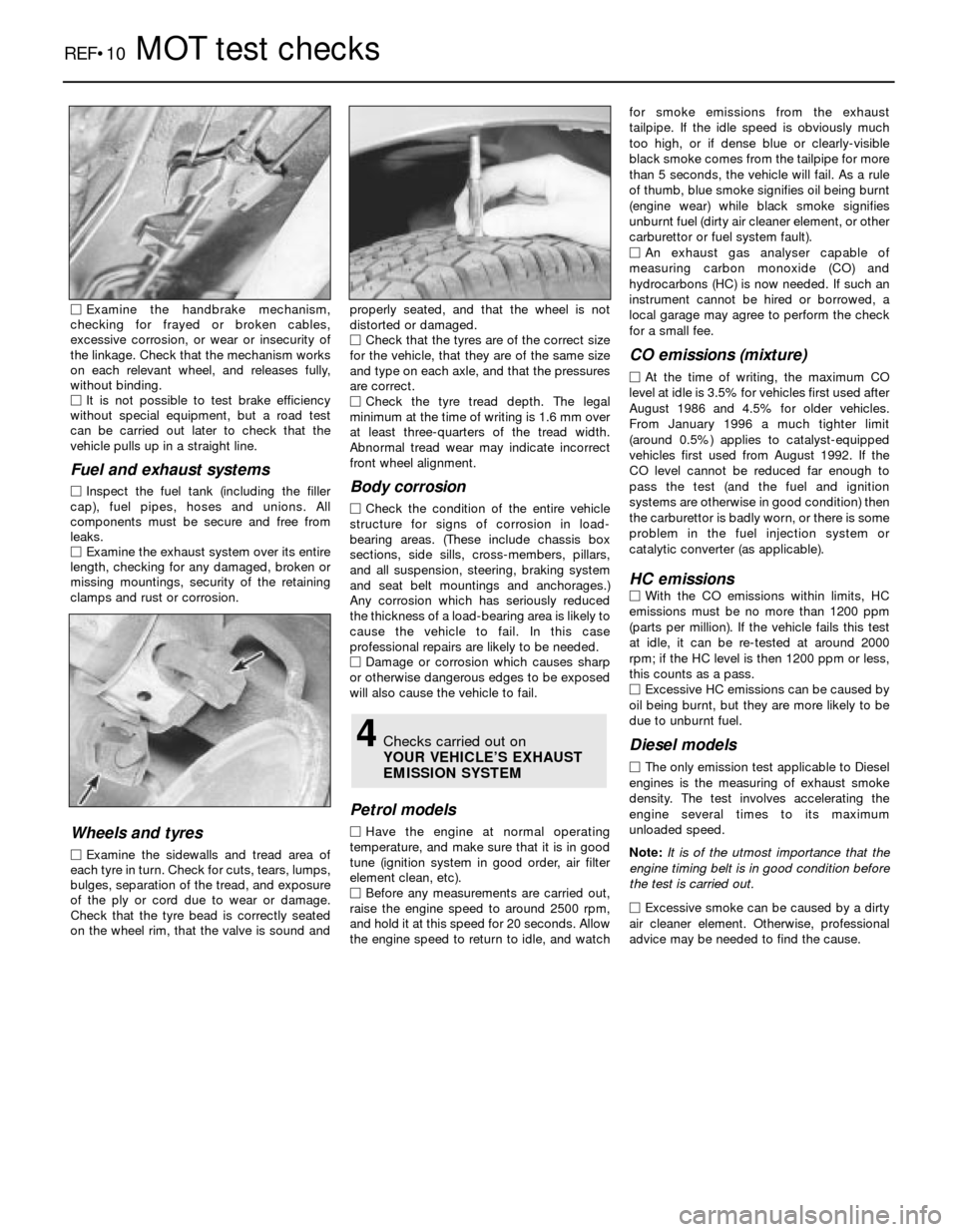
MCheck the tyre tread depth. The legal
minimum at the time of writing is 1.6 mm over
at least three-quarters of the tread width.
Abnormal tread wear may indicate incorrect
front wheel alignment.
Body corrosion
MCheck the condition of the entire vehicle
structure for signs of corrosion in load-
bearing areas. (These include chassis box
sections, side sills, cross-members, pillars,
and all suspension, steering, braking system
and seat belt mountings and anchorages.)
Any corrosion which has seriously reduced
the thickness of a load-bearing area is likely to
cause the vehicle to fail. In this case
professional repairs are likely to be needed.
MDamage or corrosion which causes sharp
or otherwise dangerous edges to be exposed
will also cause the vehicle to fail.
Petrol models
MHave the engine at normal operating
temperature, and make sure that it is in good
tune (ignition system in good order, air filter
element clean, etc).
MBefore any measurements are carried out,
raise the engine speed to around 2500 rpm,
and hold it at this speed for 20 seconds. Allow
the engine speed to return to idle, and watchfor smoke emissions from the exhaust
tailpipe. If the idle speed is obviously much
too high, or if dense blue or clearly-visible
black smoke comes from the tailpipe for more
than 5 seconds, the vehicle will fail. As a rule
of thumb, blue smoke signifies oil being burnt
(engine wear) while black smoke signifies
unburnt fuel (dirty air cleaner element, or other
carburettor or fuel system fault).
MAn exhaust gas analyser capable of
measuring carbon monoxide (CO) and
hydrocarbons (HC) is now needed. If such an
instrument cannot be hired or borrowed, a
local garage may agree to perform the check
for a small fee.
CO emissions (mixture)
MAt the time of writing, the maximum CO
level at idle is 3.5% for vehicles first used after
August 1986 and 4.5% for older vehicles.
From January 1996 a much tighter limit
(around 0.5%) applies to catalyst-equipped
vehicles first used from August 1992. If the
CO level cannot be reduced far enough to
pass the test (and the fuel and ignition
systems are otherwise in good condition) then
the carburettor is badly worn, or there is some
problem in the fuel injection system or
catalytic converter (as applicable).
HC emissionsMWith the CO emissions within limits, HC
emissions must be no more than 1200 ppm
(parts per million). If the vehicle fails this test
at idle, it can be re-tested at around 2000
rpm; if the HC level is then 1200 ppm or less,
this counts as a pass.
MExcessive HC emissions can be caused by
oil being burnt, but they are more likely to be
due to unburnt fuel.
Diesel models
MThe only emission test applicable to Diesel
engines is the measuring of exhaust smoke
density. The test involves accelerating the
engine several times to its maximum
unloaded speed.
Note: It is of the utmost importance that the
engine timing belt is in good condition before
the test is carried out.
M
Excessive smoke can be caused by a dirty
air cleaner element. Otherwise, professional
advice may be needed to find the cause.
4Checks carried out on
YOUR VEHICLE’S EXHAUST
EMISSION SYSTEM
Page 24 of 26
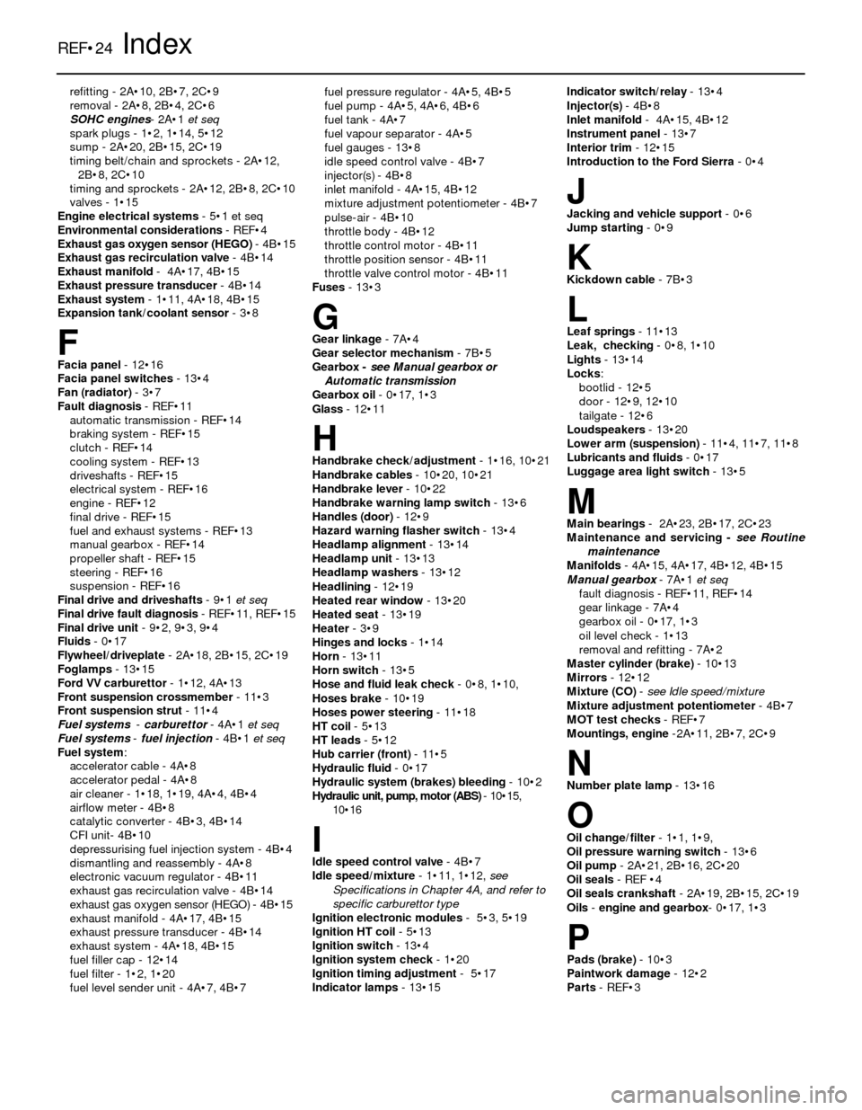
refitting - 2A•10, 2B•7, 2C•9
removal - 2A•8, 2B•4, 2C•6
SOHC engines- 2A•1et seq
spark plugs - 1•2, 1•14, 5•12
sump - 2A•20, 2B•15, 2C•19
timing belt/chain and sprockets - 2A•12,
2B•8, 2C•10
timing and sprockets - 2A•12, 2B•8, 2C•10
valves - 1•15
Engine electrical systems - 5•1 et seq
Environmental considerations- REF•4
Exhaust gas oxygen sensor (HEGO)- 4B•15
Exhaust gas recirculation valve- 4B•14
Exhaust manifold- 4A•17, 4B•15
Exhaust pressure transducer- 4B•14
Exhaust system- 1•11, 4A•18, 4B•15
Expansion tank/coolant sensor- 3•8
FFacia panel- 12•16
Facia panel switches- 13•4
Fan (radiator)- 3•7
Fault diagnosis- REF•11
automatic transmission - REF•14
braking system - REF•15
clutch - REF•14
cooling system - REF•13
driveshafts - REF•15
electrical system - REF•16
engine - REF•12
final drive - REF•15
fuel and exhaust systems - REF•13
manual gearbox - REF•14
propeller shaft - REF•15
steering - REF•16
suspension - REF•16
Final drive and driveshafts- 9•1 et seq
Final drive fault diagnosis- REF•11, REF•15
Final drive unit- 9•2, 9•3, 9•4
Fluids- 0•17
Flywheel/driveplate- 2A•18, 2B•15, 2C•19
Foglamps- 13•15
Ford VV carburettor- 1•12, 4A•13
Front suspension crossmember- 11•3
Front suspension strut- 11•4
Fuel systems- carburettor - 4A•1 et seq
Fuel systems- fuel injection - 4B•1 et seq
Fuel system:
accelerator cable - 4A•8
accelerator pedal - 4A•8
air cleaner - 1•18, 1•19, 4A•4, 4B•4
airflow meter - 4B•8
catalytic converter - 4B•3, 4B•14
CFI unit- 4B•10
depressurising fuel injection system - 4B•4
dismantling and reassembly - 4A•8
electronic vacuum regulator - 4B•11
exhaust gas recirculation valve - 4B•14
exhaust gas oxygen sensor (HEGO) - 4B•15
exhaust manifold - 4A•17, 4B•15
exhaust pressure transducer - 4B•14
exhaust system - 4A•18, 4B•15
fuel filler cap - 12•14
fuel filter - 1•2, 1•20
fuel level sender unit - 4A•7, 4B•7fuel pressure regulator - 4A•5, 4B•5
fuel pump - 4A•5, 4A•6, 4B•6
fuel tank - 4A•7
fuel vapour separator - 4A•5
fuel gauges - 13•8
idle speed control valve - 4B•7
injector(s) - 4B•8
inlet manifold - 4A•15, 4B•12
mixture adjustment potentiometer - 4B•7
pulse-air - 4B•10
throttle body - 4B•12
throttle control motor - 4B•11
throttle position sensor - 4B•11
throttle valve control motor - 4B•11
Fuses- 13•3
GGear linkage- 7A•4
Gear selector mechanism- 7B•5
Gearbox - see Manual gearbox or
Automatic transmission
Gearbox oil- 0•17, 1•3
Glass- 12•11
HHandbrake check/adjustment- 1•16, 10•21
Handbrake cables- 10•20, 10•21
Handbrake lever - 10•22
Handbrake warning lamp switch- 13•6
Handles (door)- 12•9
Hazard warning flasher switch- 13•4
Headlamp alignment- 13•14
Headlamp unit- 13•13
Headlamp washers- 13•12
Headlining - 12•19
Heated rear window- 13•20
Heated seat- 13•19
Heater- 3•9
Hinges and locks- 1•14
Horn- 13•11
Horn switch- 13•5
Hose and fluid leak check- 0•8, 1•10,
Hoses brake- 10•19
Hoses power steering- 11•18
HT coil- 5•13
HT leads- 5•12
Hub carrier (front) - 11•5
Hydraulic fluid- 0•17
Hydraulic system (brakes) bleeding- 10•2
Hydraulic unit, pump, motor (ABS)- 10•15,
10•16
IIdle speed control valve- 4B•7
Idle speed/mixture- 1•11, 1•12, see
Specifications in Chapter 4A, and refer to
specific carburettor type
Ignition electronic modules- 5•3, 5•19
Ignition HT coil- 5•13
Ignition switch- 13•4
Ignition system check- 1•20
Ignition timing adjustment- 5•17
Indicator lamps- 13•15Indicator switch/relay- 13•4
Injector(s)- 4B•8
Inlet manifold- 4A•15, 4B•12
Instrument panel- 13•7
Interior trim- 12•15
Introduction to the Ford Sierra- 0•4
JJacking and vehicle support- 0•6
Jump starting- 0•9
KKickdown cable - 7B•3
LLeaf springs- 11•13
Leak, checking- 0•8, 1•10
Lights- 13•14
Locks:
bootlid - 12•5
door - 12•9, 12•10
tailgate - 12•6
Loudspeakers- 13•20
Lower arm (suspension)- 11•4, 11•7, 11•8
Lubricants and fluids- 0•17
Luggage area light switch- 13•5
MMain bearings- 2A•23, 2B•17, 2C•23
Maintenance and servicing - see Routine
maintenance
Manifolds- 4A•15, 4A•17, 4B•12, 4B•15
Manual gearbox- 7A•1 et seq
fault diagnosis - REF•11, REF•14
gear linkage - 7A•4
gearbox oil - 0•17, 1•3
oil level check - 1•13
removal and refitting - 7A•2
Master cylinder (brake)- 10•13
Mirrors- 12•12
Mixture (CO)- see Idle speed/mixture
Mixture adjustment potentiometer- 4B•7
MOT test checks- REF•7
Mountings, engine-2A•11, 2B•7, 2C•9
NNumber plate lamp- 13•16
OOil change/filter- 1•1, 1•9,
Oil pressure warning switch- 13•6
Oil pump- 2A•21, 2B•16, 2C•20
Oil seals- REF •4
Oil seals crankshaft- 2A•19, 2B•15, 2C•19
Oils- engine and gearbox- 0•17, 1•3
PPads (brake) - 10•3
Paintwork damage- 12•2
Parts- REF•3
REF•24Index
Page 25 of 26
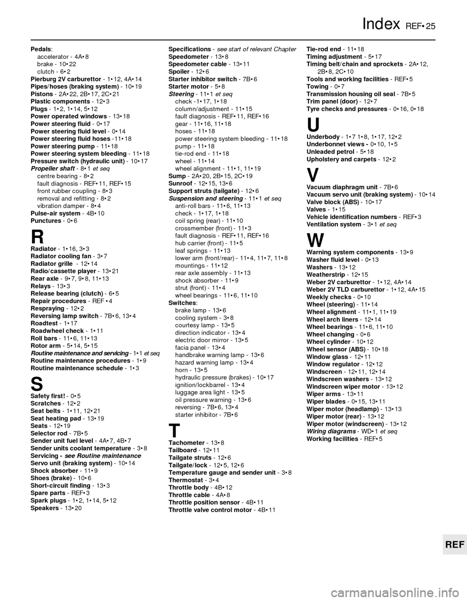
Pedals:
accelerator - 4A•8
brake - 10•22
clutch - 6•2
Pierburg 2V carburettor- 1•12, 4A•14
Pipes/hoses (braking system)- 10•19
Pistons- 2A•22, 2B•17, 2C•21
Plastic components- 12•3
Plugs- 1•2, 1•14, 5•12
Power operated windows- 13•18
Power steering fluid- 0•17
Power steering fluid level- 0•14
Power steering fluid hoses-11•18
Power steering pump- 11•18
Power steering system bleeding- 11•18
Pressure switch (hydraulic unit)- 10•17
Propeller shaft- 8•1 et seq
centre bearing - 8•2
fault diagnosis - REF•11, REF•15
front rubber coupling - 8•3
removal and refitting - 8•2
vibration damper - 8•4
Pulse-air system- 4B•10
Punctures- 0•6
RRadiator- 1•16, 3•3
Radiator cooling fan- 3•7
Radiator grille- 12•14
Radio/cassette player- 13•21
Rear axle- 9•7, 9•8, 11•13
Relays- 13•3
Release bearing (clutch)- 6•5
Repair procedures- REF •4
Respraying- 12•2
Reversing lamp switch- 7B•6, 13•4
Roadtest- 1•17
Roadwheel check- 1•11
Roll bars- 11•6, 11•13
Rotor arm- 5•14, 5•15
Routine maintenance and servicing- 1•1 et seq
Routine maintenance procedures- 1•9
Routine maintenance schedule- 1•3
SSafety first!- 0•5
Scratches- 12•2
Seat belts- 1•11, 12•21
Seat heating pad- 13•19
Seats- 12•19
Selector rod- 7B•5
Sender unit fuel level- 4A•7, 4B•7
Sender units coolant temperature- 3•8
Servicing -see Routine maintenance
Servo unit (braking system)- 10•14
Shock absorber- 11•9
Shoes (brake)- 10•6
Short-circuit finding- 13•3
Spare parts- REF•3
Spark plugs- 1•2, 1•14, 5•12
Speakers- 13•20Specifications- see start of relevant Chapter
Speedometer- 13•8
Speedometer cable- 13•11
Spoiler- 12•6
Starter inhibitor switch- 7B•6
Starter motor- 5•8
Steering- 11•1 et seq
check -1•17, 1•18
column/adjustment - 11•15
fault diagnosis - REF•11, REF•16
gear - 11•16, 11•18
hoses - 11•18
power steering system bleeding - 11•18
pump - 11•18
tie-rod end - 11•18
wheel - 11•14
wheel alignment - 11•1, 11•19
Sump- 2A•20, 2B•15, 2C•19
Sunroof- 12•15, 13•6
Support struts (tailgate)- 12•6
Suspension and steering- 11•1 et seq
anti-roll bars - 11•6, 11•13
check - 1•17, 1•18
coil spring (rear) - 11•10
crossmember (front) - 11•3
fault diagnosis - REF•11, REF•16
hub carrier (front) - 11•5
leaf springs - 11•13
lower arm (front/rear) - 11•4, 11•7, 11•8
mountings - 11•12
rear axle assembly - 11•13
shock absorber - 11•9
strut (front) - 11•4
wheel bearings - 11•6, 11•10
Switches:
brake lamp - 13•6
cooling system - 3•8
courtesy lamp - 13•5
direction indicator - 13•4
electric door mirror - 13•5
facia panel - 13•4
handbrake warning lamp - 13•6
hazard warning lamp - 13•4
horn - 13•5
hydraulic pressure (brakes) - 10•17
ignition/lockbarrel - 13•4
luggage area light - 13•5
oil pressure warning - 13•6
reversing - 7B•6, 13•4
starter inhibitor - 7B•6
TTachometer- 13•8
Tailboard- 12•11
Tailgate struts- 12•6
Tailgate/lock- 12•5, 12•6
Temperature gauge and sender unit- 3•8
Thermostat- 3•4
Throttle body- 4B•12
Throttle cable- 4A•8
Throttle position sensor- 4B•11
Throttle valve control motor- 4B•11Tie-rod end- 11•18
Timing adjustment- 5•17
Timing belt/chain and sprockets- 2A•12,
2B•8, 2C•10
Tools and working facilities- REF•5
Towing- 0•7
Transmission housing oil seal- 7B•5
Trim panel (door)- 12•7
Tyre checks and pressures- 0•16, 0•18
UUnderbody- 1•7 1•8, 1•17, 12•2
Underbonnet views -0•10, 1•5
Unleaded petrol- 5•18
Upholstery and carpets- 12•2
VVacuum diaphragm unit- 7B•6
Vacuum servo unit (braking system)- 10•14
Valve block (ABS)- 10•17
Valves- 1•15
Vehicle identification numbers- REF•3
Ventilation system- 3•1 et seq
WWarning system components- 13•9
Washer fluid level- 0•13
Washers- 13•12
Weatherstrip- 12•15
Weber 2V carburettor- 1•12, 4A•14
Weber 2V TLD carburettor- 1•12, 4A•15
Weekly checks- 0•10
Wheel (steering) - 11•14
Wheel alignment- 11•1, 11•19
Wheel arch liners- 12•14
Wheel bearings- 11•6, 11•10
Wheel changing- 0•6
Wheel cylinder- 10•12
Wheel sensor(ABS)- 10•18
Window glass- 12•11
Window regulator- 12•12
Windscreen- 12•11, 12•14
Windscreen washers- 13•12
Windscreen wiper motor- 13•12
Wiper arms- 13•11
Wiper blades- 0•15, 13•11
Wiper motor (headlamp)- 13•13
Wiper motor (rear)- 13•12
Wiper motor (windscreen)- 13•12
Wiring diagrams- WD•1 et seq
Working facilities- REF•5
IndexREF•25
REF
Page 26 of 26

Almost every car you’ve ever loved, loathed or desired is gathered under one roof at the Haynes Motor
Museum. Over 300 immaculately presented cars and motorbikes represent every aspect of our motoring
heritage, from elegant reminders of bygone days, such as the superb Model J Duesenberg to curiosities like
the bug-eyed BMW Isetta. There are also many old friends and flames. Perhaps you remember the 1959 Ford
Popular that you did your courting in? The magnificent ‘Red Collection’ is a spectacle of classic sports cars
including AC, Alfa Romeo, Austin Healey, Ferrari, Lamborghini, Maserati, MG, Riley, Porsche and Triumph.
A Perfect Day Out
Each and every vehicle at the Haynes Motor Museum has played its part in the history and culture of
Motoring. Today, they make a wonderful spectacle and a great day out for all the family. Bring the kids, bring
Mum and Dad, but above all bring your camera to capture those golden memories for ever. You will also find
an impressive array of motoring memorabilia, a comfortable 70 seat video cinema and one of the most
extensive transport book shops in Britain. The Pit Stop Cafe serves everything from a cup of tea to
wholesome, home-made meals or, if you prefer, you can enjoy the large picnic area nestled in the beautiful
rural surroundings of Somerset.
The Museum is situated on the A359 Yeovil to Frome road at Sparkford, just off the A303 in Somerset. It is about 40 miles south of Bristol, and
25 minutes drive from the M5 intersection at Taunton.
Open 9.30am - 5.30pm (10.00am - 4.00pm Winter)7 days a week, except Christmas Day, Boxing Day and New Years Day
Special rates available for schools, coach parties and outings Charitable Trust No. 292048
>John Haynes O.B.E.,
Founder and
Chairman of the
museum at the wheel
of a Haynes Light 12.
car next to a 1934
Riley Sports.
Only eight of these
magnificent cars were
ever built – this is the
only example to be found
outside the United
States of America
Preserving Our Motoring Heritage