fuse box location FORD SIERRA 1986 1.G Engine Electrical Systems Workshop Manual
[x] Cancel search | Manufacturer: FORD, Model Year: 1986, Model line: SIERRA, Model: FORD SIERRA 1986 1.GPages: 24, PDF Size: 0.93 MB
Page 22 of 24

38Before refitting the sensor, examine the
O-ring, and renew it if damaged or worn.
39Refitting is a reversal of removal, noting
the torque setting for the sensor screw.
Note: Procedures for removal and refitting of
the ignition system components and
electronic module are given elsewhere in the
relevant Sections of this Chapter.
1Disconnect the battery negative lead.
Crankshaft speed/position sensor
2The sensor is mounted in a bracket on the
timing cover.
3Disconnect the sensor wiring plug by
pulling on the plug, not the wiring (see
illustration).
4Slacken the sensor clamping screw and
slide the sensor from its bracket.
5Refitting is a reversal of removal, but the
clearance between the sensor and the
toothed wheel on the crankshaft must be set
at 1.0 mm (0.04 in). This can be achieved by
inserting a suitable length of wire or rod with a
diameter of 1.0 mm (0.04 in) between the
sensor and the toothed wheel (see
illustration). Do not overtighten the clamping
screw, as damage to the sensor may result.
Engine coolant temperature
sensor
6The sensor is located in the side of the inlet
manifold(see illustration).
7Partially drain the cooling system.
8Disconnect the sensor wiring plug by
pulling on the plug, not the wiring.
9Unscrew the sensor from the inlet manifold
and remove it.
10Refitting is a reversal of removal. Fill the
cooling system.
Air charge temperature sensor
11The sensor is located in the base of the air
cleaner.
12Remove the air cleaner.
13Disconnect the sensor wiring plug by
pulling on the plug, not the wiring (see
illustration).14Unscrew the sensor from the air cleaner
using a suitable spanner.
15Refitting is a reversal of removal. Refit the
air cleaner. Ensure that the vacuum hose is
securely connected.
Electric choke heater
16The electric choke heater is an integral
part of the automatic choke housing on the
carburettor. Removal and refitting of the
choke housing is covered in Chapter 4.
17The operation of the electric choke heater
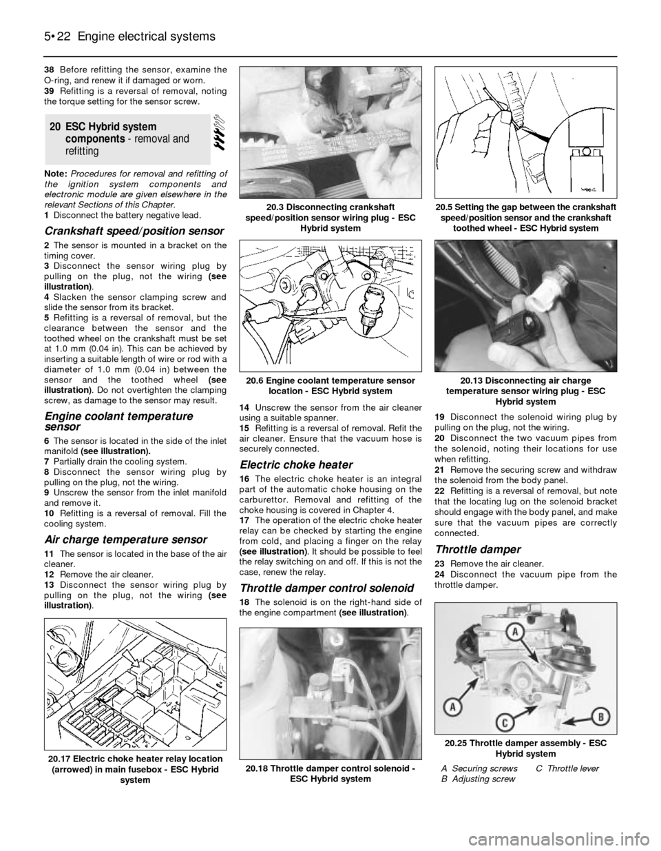
relay can be checked by starting the engine
from cold, and placing a finger on the relay
(see illustration). It should be possible to feel
the relay switching on and off. If this is not the
case, renew the relay.
Throttle damper control solenoid
18The solenoid is on the right-hand side of
the engine compartment (see illustration). 19Disconnect the solenoid wiring plug by
pulling on the plug, not the wiring.
20Disconnect the two vacuum pipes from
the solenoid, noting their locations for use
when refitting.
21Remove the securing screw and withdraw
the solenoid from the body panel.
22Refitting is a reversal of removal, but note
that the locating lug on the solenoid bracket
should engage with the body panel, and make
sure that the vacuum pipes are correctly
connected.
Throttle damper
23Remove the air cleaner.
24Disconnect the vacuum pipe from the
throttle damper.
20ESC Hybrid system
components - removal and
refitting
5•22Engine electrical systems
20.3 Disconnecting crankshaft
speed/position sensor wiring plug - ESC
Hybrid system
20.6 Engine coolant temperature sensor
location - ESC Hybrid system
20.25 Throttle damper assembly - ESC
Hybrid system
A Securing screws
B Adjusting screwC Throttle lever20.18 Throttle damper control solenoid -
ESC Hybrid system20.17 Electric choke heater relay location
(arrowed) in main fusebox - ESC Hybrid
system
20.13 Disconnecting air charge
temperature sensor wiring plug - ESC
Hybrid system
20.5 Setting the gap between the crankshaft
speed/position sensor and the crankshaft
toothed wheel - ESC Hybrid system