ESP FORD SIERRA 1986 1.G Routine Manintenance And Servicing Workshop Manual
[x] Cancel search | Manufacturer: FORD, Model Year: 1986, Model line: SIERRA, Model: FORD SIERRA 1986 1.GPages: 22, PDF Size: 1.26 MB
Page 11 of 22

4Carefully check the condition of all coolant,
fuel, power steering and brake hoses. Renew
any hose which is cracked, swollen or
deteriorated. Cracks will show up better if the
hose is squeezed. Pay close attention to the
hose clips that secure the hoses to the system
components. Hose clips can pinch and
puncture hoses, resulting in leaks. If wire type
hose clips are used, it may be a good idea to
replace them with screw-type clips.
5With the vehicle raised, inspect the fuel
tank and filler neck for punctures, cracks and
other damage. The connection between the
filler neck and tank is especially critical.
Sometimes a rubber filler neck or connecting
hose will leak due to loose retaining clamps or
deteriorated rubber.
6Similarly, inspect all brake hoses and metal
pipes. If any damage or deterioration is
discovered, do not drive the vehicle until the
necessary repair work has been carried out.
Renew any damaged sections of hose or pipe.
7Carefully check all rubber hoses and metal
fuel lines leading away from the petrol tank.
Check for loose connections, deteriorated
hoses, crimped lines and other damage. Pay
particular attention to the vent pipes and
hoses which often loop up around the filler
neck and can become blocked or crimped.
Follow the lines to the front of the vehicle
carefully inspecting them all the way. Renew
damaged sections as necessary.
8From within the engine compartment,
check the security of all fuel hose attachments
and pipe unions, and inspect the fuel hoses
and vacuum hoses for kinks, chafing and
deterioration.
9Where applicable, check the condition of
the oil cooler hoses and pipes.
10Check the condition of all exposed wiring
harnesses.
1Periodically check the belts for fraying or
other damage. If evident, renew the belt.
2If the belts become dirty, wipe them with a
damp cloth using a little detergent only.
3Check the tightness of the anchor bolts and
if they are ever disconnected, make quite sure
that the original sequence of fitting of
washers, bushes and anchor plates is
retained.
With the vehicle raised on a hoist or
supported on axle stands, check the exhaust
system for signs of leaks, corrosion or
damage and check the rubber mountings for
condition and security. Where damage or
corrosion are evident, renew the system
complete or in sections, as applicable, using
the information given in Chapter 4.With the wheels on the ground, slacken each
wheel nut by a quarter turn, then retighten it
immediately to the specified torque.
Remove and clean the oil filler cap of any
sludge build-up using paraffin.
Inspect the vent hose for blockage or
damage. A blocked hose can cause a build-
up of crankcase pressure, which in turn can
cause oil leaks.
Ford VV carburettor
1Ensure that the air cleaner is correctly fitted,
and that all vacuum hoses and pipes are
securely connected and free from restrictions,
then run the engine until it is at normal
operating temperature.
2Stop the engine, and connect a tachometer
and an exhaust gas analyser in accordance
with the manufacturer’s instructions.
3Start the engine and run it at 3000 rpm for
30 seconds, ensuring that all electrical loads
are switched off (headlamps, heater blower
etc), then allow the engine to idle and check
the idle speed and CO content. Note that the
CO reading will initially rise, then fall and finally
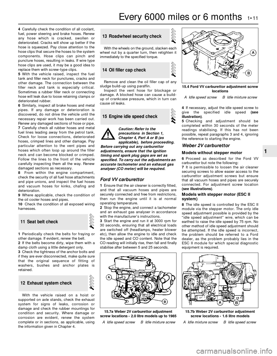
stabilise after between 5 and 25 seconds.4If necessary, adjust the idle speed screw to
give the specified idle speed (see
illustration).
5Checking and adjustment should be
completed within 30 seconds of the meter
readings stabilising. If this has not been
possible, repeat paragraphs 3 and 4, ignoring
the reference to starting the engine.
Weber 2V carburettor
Models without stepper motor
6Proceed as described for the Ford VV
carburettor but note the following:
7It is permissible to loosen the air cleaner
securing screws to allow easier access to the
carburettor adjustment screws but ensure
that all vacuum hoses and pipes are securely
connected. For adjustment screw location
(see illustrations).
Models with stepper motor (ESC II
system)
8The idle speed is controlled by the ESC II
module via the stepper motor. The only idle
speed adjustment possible is provided by the
“idle speed adjustment” wire, which can be
earthed to raise the idle speed by 75 rpm. No
other method of idle speed adjustment should
be attempted. If the idle speed is incorrect,
the problem should be referred to a Ford
dealer, as the problem probably lies in the
ESC II module for which special diagnostic
equipment is required.
15Engine idle speed check
14Oil filler cap check
13Roadwheel security check
12Exhaust system check
11Seat belt check
Every 6000 miles or 6 months 1•11
1
15.7b Weber 2V carburettor adjustment
screw locations - 1.6 litre models
A Idle mixture screwB Idle speed screw
15.7a Weber 2V carburettor adjustment
screw locations - 2.0 litre models up to 1985
A Idle speed screwB Idle mixture screw
15.4 Ford VV carburettor adjustment screw
locations
A Idle speed screwB Idle mixture screw
Caution: Refer to the
precautions in Section 1,
Chapter 4, Part A or B (as
applicable), before proceeding.
Before carrying out any carburettor
adjustments, ensure that the ignition
timing and spark plug gaps are set as
specified. To carry out the adjustments an
accurate tachometer and an exhaust gas
analyser (CO meter) will be required.