key battery FORD SIERRA 1990 2.G CVH Engines Workshop Manual
[x] Cancel search | Manufacturer: FORD, Model Year: 1990, Model line: SIERRA, Model: FORD SIERRA 1990 2.GPages: 24, PDF Size: 1.09 MB
Page 12 of 24

16Where applicable, refit the timing belt
tensioner and coolant pump, locate the timing
belt backplate over the studs, then fit the
camshaft sprocket and the distributor rotor
shaft.
17The camshaft sprocket bolt must be
coated with sealant before installation. The
manufacturers recommend Loctite 74 or 274,
or Omnifit 30M blue. With the sealant applied,
insert the bolt, hold the camshaft sprocket
stationary as during removal, and tighten the
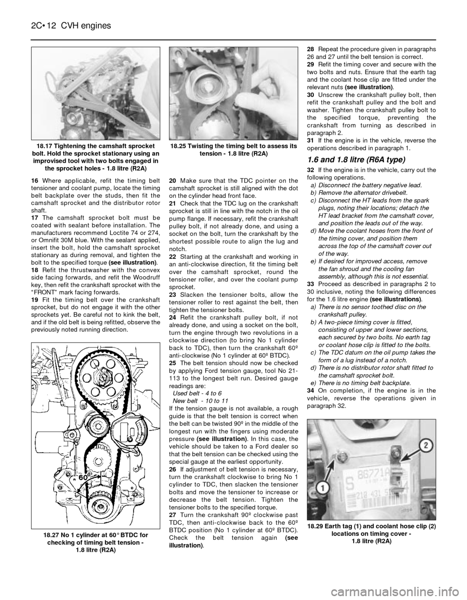
bolt to the specified torque (see illustration).
18Refit the thrustwasher with the convex
side facing forwards, and refit the Woodruff
key, then refit the crankshaft sprocket with the
“FRONT” mark facing forwards.
19Fit the timing belt over the crankshaft
sprocket, but do not engage it with the other
sprockets yet. Be careful not to kink the belt,
and if the old belt is being refitted, observe the
previously noted running direction.20Make sure that the TDC pointer on the
camshaft sprocket is still aligned with the dot
on the cylinder head front face.
21Check that the TDC lug on the crankshaft
sprocket is still in line with the notch in the oil
pump flange. If necessary, refit the crankshaft
pulley bolt, if not already done, and using a
socket on the bolt, turn the crankshaft by the
shortest possible route to align the lug and
notch.
22Starting at the crankshaft and working in
an anti-clockwise direction, fit the timing belt
over the camshaft sprocket, round the
tensioner roller, and over the coolant pump
sprocket.
23Slacken the tensioner bolts, allow the
tensioner roller to rest against the belt, then
tighten the tensioner bolts.
24Refit the crankshaft pulley bolt, if not
already done, and using a socket on the bolt,
turn the engine through two revolutions in a
clockwise direction (to bring No 1 cylinder
back to TDC), then turn the crankshaft 60º
anti-clockwise (No 1 cylinder at 60º BTDC).
25The belt tension should now be checked
by applying Ford tension gauge, tool No 21-
113 to the longest belt run. Desired gauge
readings are:
Used belt - 4 to 6
New belt - 10 to 11
If the tension gauge is not available, a rough
guide is that the belt tension is correct when
the belt can be twisted 90º in the middle of the
longest run with the fingers using moderate
pressure (see illustration). In this case, the
vehicle should be taken to a Ford dealer so
that the belt tension can be checked using the
special gauge at the earliest opportunity.
26If adjustment of belt tension is necessary,
turn the crankshaft clockwise to bring No 1
cylinder to TDC, then slacken the tensioner
bolts and move the tensioner to increase or
decrease the belt tension. Tighten the
tensioner bolts to the specified torque.
27Turn the crankshaft 90º clockwise past
TDC, then anti-clockwise back to the 60º
BTDC position (No 1 cylinder at 60º BTDC).
Check the belt tension again (see
illustration).28Repeat the procedure given in paragraphs
26 and 27 until the belt tension is correct.
29Refit the timing cover and secure with the
two bolts and nuts. Ensure that the earth tag
and the coolant hose clip are fitted under the
relevant nuts (see illustration).
30Unscrew the crankshaft pulley bolt, then
refit the crankshaft pulley and the bolt and
washer. Tighten the crankshaft pulley bolt to
the specified torque, preventing the
crankshaft from turning as described in
paragraph 2.
31If the engine is in the vehicle, reverse the
operations described in paragraph 1.
1.6 and 1.8 litre (R6A type)
32If the engine is in the vehicle, carry out the
following operations.
a)Disconnect the battery negative lead.
b)Remove the alternator drivebelt.
c)Disconnect the HT leads from the spark
plugs, noting their locations; detach the
HT lead bracket from the camshaft cover,
and position the leads out of the way.
d)Move the coolant hoses from the front of
the timing cover, and position them
across the top of the camshaft cover out
of the way.
e)If desired for improved access, remove
the fan shroud and the cooling fan
assembly, although this is not essential.
33Proceed as described in paragraphs 2 to
30 inclusive, noting the following differences
for the 1.6 litre engine (see illustrations).
a)There is no sensor toothed disc on the
crankshaft pulley.
b)A two-piece timing cover is fitted,
consisting of upper and lower sections,
each secured by two bolts. No earth tag
or coolant hose clip is fitted to the bolts.
c)The TDC datum on the oil pump takes the
form of a lug instead of a notch.
d)There is no distributor rotor shaft fitted to
the camshaft sprocket bolt.
e)There is no timing belt backplate.
34On completion, if the engine is in the
vehicle, reverse the operations given in
paragraph 32.
2C•12CVH engines
18.17 Tightening the camshaft sprocket
bolt. Hold the sprocket stationary using an
improvised tool with two bolts engaged in
the sprocket holes - 1.8 litre (R2A)
18.27 No 1 cylinder at 60°BTDC for
checking of timing belt tension -
1.8 litre (R2A)
18.29 Earth tag (1) and coolant hose clip (2)
locations on timing cover -
1.8 litre (R2A)
18.25 Twisting the timing belt to assess its
tension - 1.8 litre (R2A)