steering FORD SIERRA 1991 2.G Body Electrical System Workshop Manual
[x] Cancel search | Manufacturer: FORD, Model Year: 1991, Model line: SIERRA, Model: FORD SIERRA 1991 2.GPages: 25, PDF Size: 1.7 MB
Page 4 of 25
Removal
1Disconnect the battery negative lead.
2For improved access, remove the securing
screws and unclip the lower and upper
steering column shrouds.
3Insert the ignition key and turn to position
“I”, then, working through the access hole,
depress the spring clip using a suitable tool
and pull the key to withdraw the lock barrel
and cylinder from the ignition switch housing.
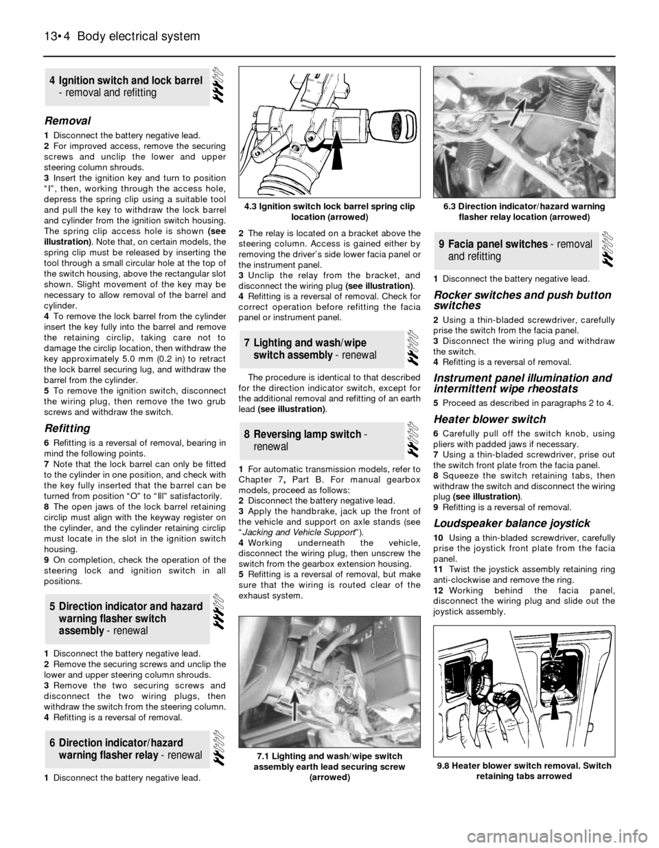
The spring clip access hole is shown (see
illustration). Note that, on certain models, the
spring clip must be released by inserting the
tool through a small circular hole at the top of
the switch housing, above the rectangular slot
shown. Slight movement of the key may be
necessary to allow removal of the barrel and
cylinder.
4To remove the lock barrel from the cylinder
insert the key fully into the barrel and remove
the retaining circlip, taking care not to
damage the circlip location, then withdraw the
key approximately 5.0 mm (0.2 in) to retract
the lock barrel securing lug, and withdraw the
barrel from the cylinder.
5To remove the ignition switch, disconnect
the wiring plug, then remove the two grub
screws and withdraw the switch.
Refitting
6Refitting is a reversal of removal, bearing in
mind the following points.
7Note that the lock barrel can only be fitted
to the cylinder in one position, and check with
the key fully inserted that the barrel can be
turned from position “O” to “Ill” satisfactorily.
8The open jaws of the lock barrel retaining
circlip must align with the keyway register on
the cylinder, and the cylinder retaining circlip
must locate in the slot in the ignition switch
housing.
9On completion, check the operation of the
steering lock and ignition switch in all
positions.
1Disconnect the battery negative lead.
2Remove the securing screws and unclip the
lower and upper steering column shrouds.
3Remove the two securing screws and
disconnect the two wiring plugs, then
withdraw the switch from the steering column.
4Refitting is a reversal of removal.
1Disconnect the battery negative lead.2The relay is located on a bracket above the
steering column. Access is gained either by
removing the driver’s side lower facia panel or
the instrument panel.
3Unclip the relay from the bracket, and
disconnect the wiring plug (see illustration).
4Refitting is a reversal of removal. Check for
correct operation before refitting the facia
panel or instrument panel.
The procedure is identical to that described
for the direction indicator switch, except for
the additional removal and refitting of an earth
lead (see illustration).
1For automatic transmission models, refer to
Chapter 7, PartB. For manual gearbox
models, proceed as follows:
2Disconnect the battery negative lead.
3Apply the handbrake, jack up the front of
the vehicle and support on axle stands (see
“Jacking and Vehicle Support”).
4Working underneath the vehicle,
disconnect the wiring plug, then unscrew the
switch from the gearbox extension housing.
5Refitting is a reversal of removal, but make
sure that the wiring is routed clear of the
exhaust system.1Disconnect the battery negative lead.
Rocker switches and push button
switches
2Using a thin-bladed screwdriver, carefully
prise the switch from the facia panel.
3Disconnect the wiring plug and withdraw
the switch.
4Refitting is a reversal of removal.
Instrument panel illumination and
intermittent wipe rheostats
5Proceed as described in paragraphs 2 to 4.
Heater blower switch
6Carefully pull off the switch knob, using
pliers with padded jaws if necessary.
7Using a thin-bladed screwdriver, prise out
the switch front plate from the facia panel.
8Squeeze the switch retaining tabs, then
withdraw the switch and disconnect the wiring
plug (see illustration).
9Refitting is a reversal of removal.
Loudspeaker balance joystick
10Using a thin-bladed screwdriver, carefully
prise the joystick front plate from the facia
panel.
11Twist the joystick assembly retaining ring
anti-clockwise and remove the ring.
12Working behind the facia panel,
disconnect the wiring plug and slide out the
joystick assembly.
9Facia panel switches - removal
and refitting
8Reversing lamp switch -
renewal
7Lighting and wash/wipe
switch assembly - renewal
6Direction indicator/hazard
warning flasher relay - renewal
5Direction indicator and hazard
warning flasher switch
assembly - renewal
4Ignition switch and lock barrel
- removal and refitting
13•4Body electrical system
4.3 Ignition switch lock barrel spring clip
location (arrowed)
7.1 Lighting and wash/wipe switch
assembly earth lead securing screw
(arrowed)9.8 Heater blower switch removal. Switch
retaining tabs arrowed
6.3 Direction indicator/hazard warning
flasher relay location (arrowed)
Page 5 of 25
13Refitting is a reversal of removal, but note
that the wiring plug can only be fitted in one
position, and ensure that the joystick
assembly locating lug engages in the
corresponding hole in the facia panel.
1Disconnect the battery negative lead.
Models up to 1987
2Using a thin-bladed screwdriver, carefully
prise the switch from the door trim panel.
3Disconnect the wiring plug and withdraw
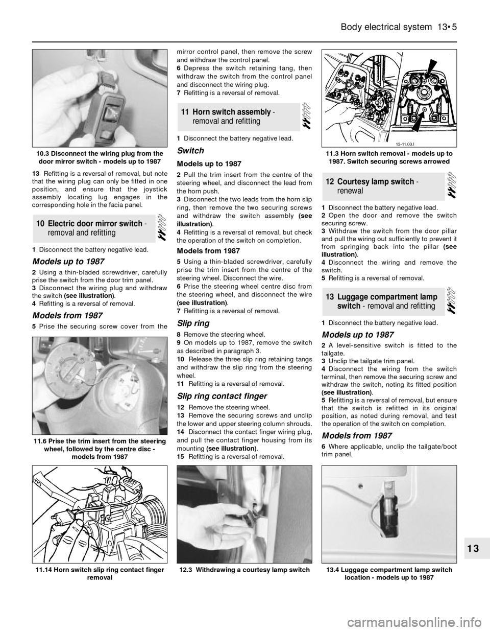
the switch (see illustration).
4Refitting is a reversal of removal.
Models from 1987
5Prise the securing screw cover from themirror control panel, then remove the screw
and withdraw the control panel.
6Depress the switch retaining tang, then
withdraw the switch from the control panel
and disconnect the wiring plug.
7Refitting is a reversal of removal.
1Disconnect the battery negative lead.
Switch
Models up to 1987
2Pull the trim insert from the centre of the
steering wheel, and disconnect the lead from
the horn push.
3Disconnect the two leads from the horn slip
ring, then remove the two securing screws
and withdraw the switch assembly (see
illustration).
4Refitting is a reversal of removal, but check
the operation of the switch on completion.
Models from 1987
5Using a thin-bladed screwdriver, carefully
prise the trim insert from the centre of the
steering wheel. Disconnect the wire.
6Prise the steering wheel centre disc from
the steering wheel, and disconnect the wire
(see illustration).
7Refitting is a reversal of removal.
Slip ring
8Remove the steering wheel.
9On models up to 1987, remove the switch
as described in paragraph 3.
10Release the three slip ring retaining tangs
and withdraw the slip ring from the steering
wheel.
11Refitting is a reversal of removal.
Slip ring contact finger
12Remove the steering wheel.
13Remove the securing screws and unclip
the lower and upper steering column shrouds.
14Disconnect the contact finger wiring plug,
and pull the contact finger housing from its
mounting (see illustration).
15Refitting is a reversal of removal.1Disconnect the battery negative lead.
2Open the door and remove the switch
securing screw.
3Withdraw the switch from the door pillar
and pull the wiring out sufficiently to prevent it
from springing back into the pillar (see
illustration).
4Disconnect the wiring and remove the
switch.
5Refitting is a reversal of removal.
1Disconnect the battery negative lead.
Models up to 1987
2A level-sensitive switch is fitted to the
tailgate.
3Unclip the tailgate trim panel.
4Disconnect the wiring from the switch
terminal, then remove the securing screw and
withdraw the switch, noting its fitted position
(see illustration).
5Refitting is a reversal of removal, but ensure
that the switch is refitted in its original
position, as noted during removal, and test
the operation of the switch on completion.
Models from 1987
6Where applicable, unclip the tailgate/boot
trim panel.
13Luggage compartment lamp
switch - removal and refitting
12Courtesy lamp switch -
renewal
11Horn switch assembly -
removal and refitting
10Electric door mirror switch -
removal and refitting
Body electrical system 13•5
13
11.6 Prise the trim insert from the steering
wheel, followed by the centre disc -
models from 1987
13.4 Luggage compartment lamp switch
location - models up to 198712.3 Withdrawing a courtesy lamp switch11.14 Horn switch slip ring contact finger
removal
11.3 Horn switch removal - models up to
1987. Switch securing screws arrowed10.3 Disconnect the wiring plug from the
door mirror switch - models up to 1987
Page 7 of 25
Models up to 1992
1Disconnect the battery negative lead.
2Remove the securing screws and unclip the
lower and upper steering column shrouds.
3Where applicable, remove the instrument
panel illumination and intermittent wiper
rheostats.
4Unclip the cover for access to the lower
right-hand instrument panel surround
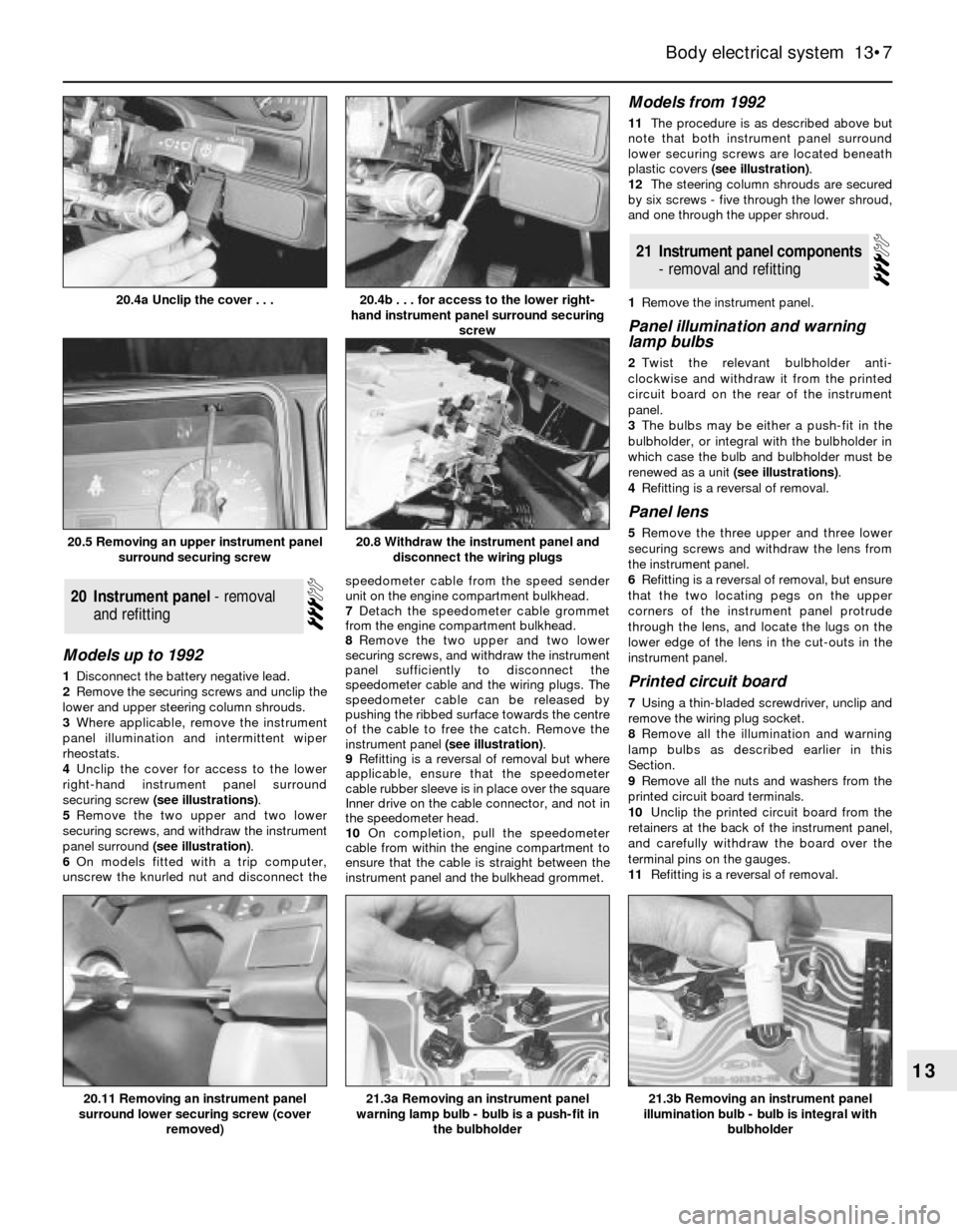
securing screw (see illustrations).
5Remove the two upper and two lower
securing screws, and withdraw the instrument
panel surround (see illustration).
6On models fitted with a trip computer,
unscrew the knurled nut and disconnect thespeedometer cable from the speed sender
unit on the engine compartment bulkhead.
7Detach the speedometer cable grommet
from the engine compartment bulkhead.
8Remove the two upper and two lower
securing screws, and withdraw the instrument
panel sufficiently to disconnect the
speedometer cable and the wiring plugs. The
speedometer cable can be released by
pushing the ribbed surface towards the centre
of the cable to free the catch. Remove the
instrument panel (see illustration).
9Refitting is a reversal of removal but where
applicable, ensure that the speedometer
cable rubber sleeve is in place over the square
Inner drive on the cable connector, and not in
the speedometer head.
10On completion, pull the speedometer
cable from within the engine compartment to
ensure that the cable is straight between the
instrument panel and the bulkhead grommet.
Models from 1992
11The procedure is as described above but
note that both instrument panel surround
lower securing screws are located beneath
plastic covers (see illustration).
12The steering column shrouds are secured
by six screws - five through the lower shroud,
and one through the upper shroud.
1Remove the instrument panel.
Panel illumination and warning
lamp bulbs
2Twist the relevant bulbholder anti-
clockwise and withdraw it from the printed
circuit board on the rear of the instrument
panel.
3The bulbs may be either a push-fit in the
bulbholder, or integral with the bulbholder in
which case the bulb and bulbholder must be
renewed as a unit (see illustrations).
4Refitting is a reversal of removal.
Panel lens
5Remove the three upper and three lower
securing screws and withdraw the lens from
the instrument panel.
6Refitting is a reversal of removal, but ensure
that the two locating pegs on the upper
corners of the instrument panel protrude
through the lens, and locate the lugs on the
lower edge of the lens in the cut-outs in the
instrument panel.
Printed circuit board
7Using a thin-bladed screwdriver, unclip and
remove the wiring plug socket.
8Remove all the illumination and warning
lamp bulbs as described earlier in this
Section.
9Remove all the nuts and washers from the
printed circuit board terminals.
10Unclip the printed circuit board from the
retainers at the back of the instrument panel,
and carefully withdraw the board over the
terminal pins on the gauges.
11Refitting is a reversal of removal.
21Instrument panel components
- removal and refitting
20Instrument panel - removal
and refitting
Body electrical system 13•7
13
20.5 Removing an upper instrument panel
surround securing screw
21.3b Removing an instrument panel
illumination bulb - bulb is integral with
bulbholder21.3a Removing an instrument panel
warning lamp bulb - bulb is a push-fit in
the bulbholder20.11 Removing an instrument panel
surround lower securing screw (cover
removed)
20.8 Withdraw the instrument panel and
disconnect the wiring plugs
20.4b . . . for access to the lower right-
hand instrument panel surround securing
screw20.4a Unclip the cover . . .
Page 10 of 25
dipstick from its tube and disconnect the
wiring plug.
31Refitting is a reversal of removal.
1Remove the instrument panel.
2Unclip the direction indicator relay from the
steering column support bracket (see
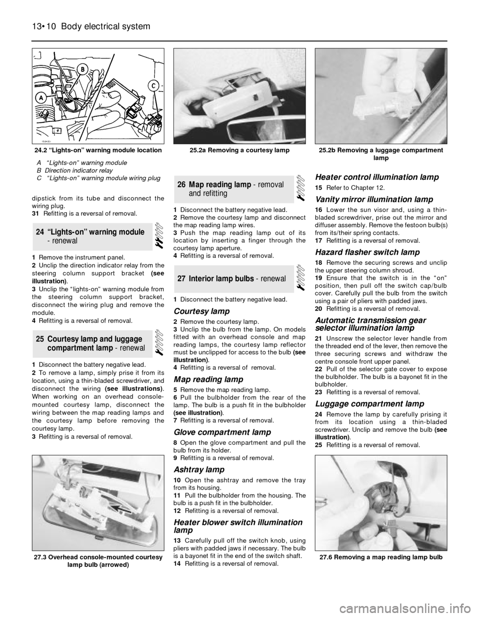
illustration).
3Unclip the “lights-on” warning module from
the steering column support bracket,
disconnect the wiring plug and remove the
module.
4Refitting is a reversal of removal.
1Disconnect the battery negative lead.
2To remove a lamp, simply prise it from its
location, using a thin-bladed screwdriver, and
disconnect the wiring (see illustrations).
When working on an overhead console-
mounted courtesy lamp, disconnect the
wiring between the map reading lamps and
the courtesy lamp before removing the
courtesy lamp.
3Refitting is a reversal of removal.1Disconnect the battery negative lead.
2Remove the courtesy lamp and disconnect
the map reading lamp wires.
3Push the map reading lamp out of its
location by inserting a finger through the
courtesy lamp aperture.
4Refitting is a reversal of removal.
1Disconnect the battery negative lead.
Courtesy lamp
2Remove the courtesy lamp.
3Unclip the bulb from the lamp. On models
fitted with an overhead console and map
reading lamps, the courtesy lamp reflector
must be unclipped for access to the bulb (see
illustration).
4Refitting is a reversal of removal.
Map reading lamp
5Remove the map reading lamp.
6Pull the bulbholder from the rear of the
lamp. The bulb is a push fit in the bulbholder
(see illustration).
7Refitting is a reversal of removal.
Glove compartment lamp
8Open the glove compartment and pull the
bulb from its holder.
9Refitting is a reversal of removal.
Ashtray lamp
10Open the ashtray and remove the tray
from its housing.
11Pull the bulbholder from the housing. The
bulb is a push fit in the bulbholder.
12Refitting is a reversal of removal.
Heater blower switch illumination
lamp
13Carefully pull off the switch knob, using
pliers with padded jaws if necessary. The bulb
is a bayonet fit in the end of the switch shaft.
14Refitting is a reversal of removal.
Heater control illumination lamp
15Refer to Chapter 12.
Vanity mirror illumination lamp
16Lower the sun visor and, using a thin-
bladed screwdriver, prise out the mirror and
diffuser assembly. Remove the festoon bulb(s)
from its/their spring contacts.
17Refitting is a reversal of removal.
Hazard flasher switch lamp
18Remove the securing screws and unclip
the upper steering column shroud.
19Ensure that the switch is in the “on”
position, then pull off the switch cap/bulb
cover. Carefully pull the bulb from the switch
using a pair of pliers with padded jaws.
20Refitting is a reversal of removal.
Automatic transmission gear
selector illumination lamp
21Unscrew the selector lever handle from
the threaded end of the lever, then remove the
three securing screws and withdraw the
centre console front upper panel.
22Pull of the selector gate cover to expose
the bulbholder. The bulb is a bayonet fit in the
bulbholder.
23Refitting is a reversal of removal.
Luggage compartment lamp
24Remove the lamp by carefully prising it
from its location using a thin-bladed
screwdriver. Unclip and remove the bulb (see
illustration).
25Refitting is a reversal of removal.
27Interior lamp bulbs - renewal
26Map reading lamp - removal
and refitting
25Courtesy lamp and luggage
compartment lamp - renewal
24“Lights-on” warning module
- renewal
13•10Body electrical system
24.2 “Lights-on” warning module location
A “Lights-on” warning module
B Direction indicator relay
C “Lights-on” warning module wiring plug
25.2b Removing a luggage compartment
lamp
27.6 Removing a map reading lamp bulb27.3 Overhead console-mounted courtesy
lamp bulb (arrowed)
25.2a Removing a courtesy lamp
Page 15 of 25
P100 models
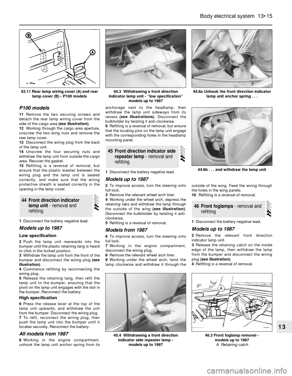
11Remove the two securing screws and
detach the rear lamp wiring cover from the
side of the cargo area(see illustration).
12Working through the cargo area aperture,
unscrew the two wing nuts and remove the
rear lamp cover.
13Disconnect the wiring plug from the back
of the lamp unit.
14Unscrew the four securing nuts and
withdraw the lamp unit from outside the cargo
area. Recover the gasket.
15Refitting is a reversal of removal, but
ensure that the plastic washer between the
wiring plug and the lamp unit is seated
correctly, and make sure that the wiring
protective sheath is seated correctly in the
opening in the lamp cover.
1Disconnect the battery negative lead.
Models up to 1987
Low specification
2Push the lamp unit rearwards into the
bumper until the plastic retaining tang is heard
to click in the locked position.
3Withdraw the lamp unit from the front of the
bumper and disconnect the wiring plug (see
illustration).
4Commence refitting by reconnecting the
wiring plug.
5Release the retaining tang, then refit the
lamp unit to the bumper, ensuring that the
pivot on the lamp unit engages with the slot in
the bumper. Reconnect the battery.
High specification
6Press the release lever at the top of the
lamp unit upwards, and withdraw the unit
from the bumper. Disconnect the wiring plug.
7To refit, reconnect the wiring plug, then
push the lamp unit into the bumper until it
locates securely. Reconnect the battery.
All models from 1987
8Working in the engine compartment,
unhook the lamp unit anchor spring from itsanchorage next to the headlamp, then
withdraw the lamp unit sideways from its
recess (see illustrations). Disconnect the
bulbholder by twisting it anti-clockwise.
9Refitting is a reversal of removal, but ensure
that the locating pins on the lamp unit engage
with the corresponding holes in the headlamp
mounting panel.
1Disconnect the battery negative lead.
Models up to 1987
2To improve access, turn the steering onto
full lock.
3Remove the relevant wheel arch liner.
4Working under the wheel arch, depress the
retaining tabs and withdraw the lamp through
the outside of the wing (see illustration).
Disconnect the bulbholder by twisting it anti-
clockwise.
5Refitting is a reversal of removal.
Models from 1987
6To improve access, turn the steering onto
full lock.
7Working in the engine compartment,
disconnect the wiring plug.
8Remove the relevant wheel arch liner.
9Working under the wheel arch, twist the
lamp clockwise and withdraw it through theoutside of the wing. Feed the wiring through
the holes in the wing panels.
10Refitting is a reversal of removal.
1Disconnect the battery negative lead.
Models up to 1987
2Remove the relevant front direction
indicator lamp unit.
3Release the retaining catch on the inside
edge of the lamp, then withdraw the lamp
from the bumper and disconnect the wiring
plug (see illustration).
4Refitting is a reversal of removal.
46Front foglamps - removal and
refitting
45Front direction indicator side
repeater lamp - removal and
refitting
44Front direction indicator
lamp unit - removal and
refitting
Body electrical system 13•15
13
44.8a Unhook the front direction indicator
lamp unit anchor spring . . .
46.3 Front foglamp removal -
models up to 1987
A Retaining catch45.4 Withdrawing a front direction
indicator side repeater lamp -
models up to 1987
44.8b . . . and withdraw the lamp unit
44.3 Withdrawing a front direction
indicator lamp unit - “low specification”
models up to 198743.11 Rear lamp wiring cover (A) and rear
lamp cover (B) - P100 models
Page 17 of 25
12Disconnect the wiring from the bulb, then
release the spring clip and withdraw the bulb.
Do not touch the bulb glass.
13Refitting is a reversal of removal.
Front direction indicator lamps
Models up to 1987
14Remove the lamp unit.
15Twist the bulbholder anti-clockwise and
withdraw it from the rear of the lamp. The bulb
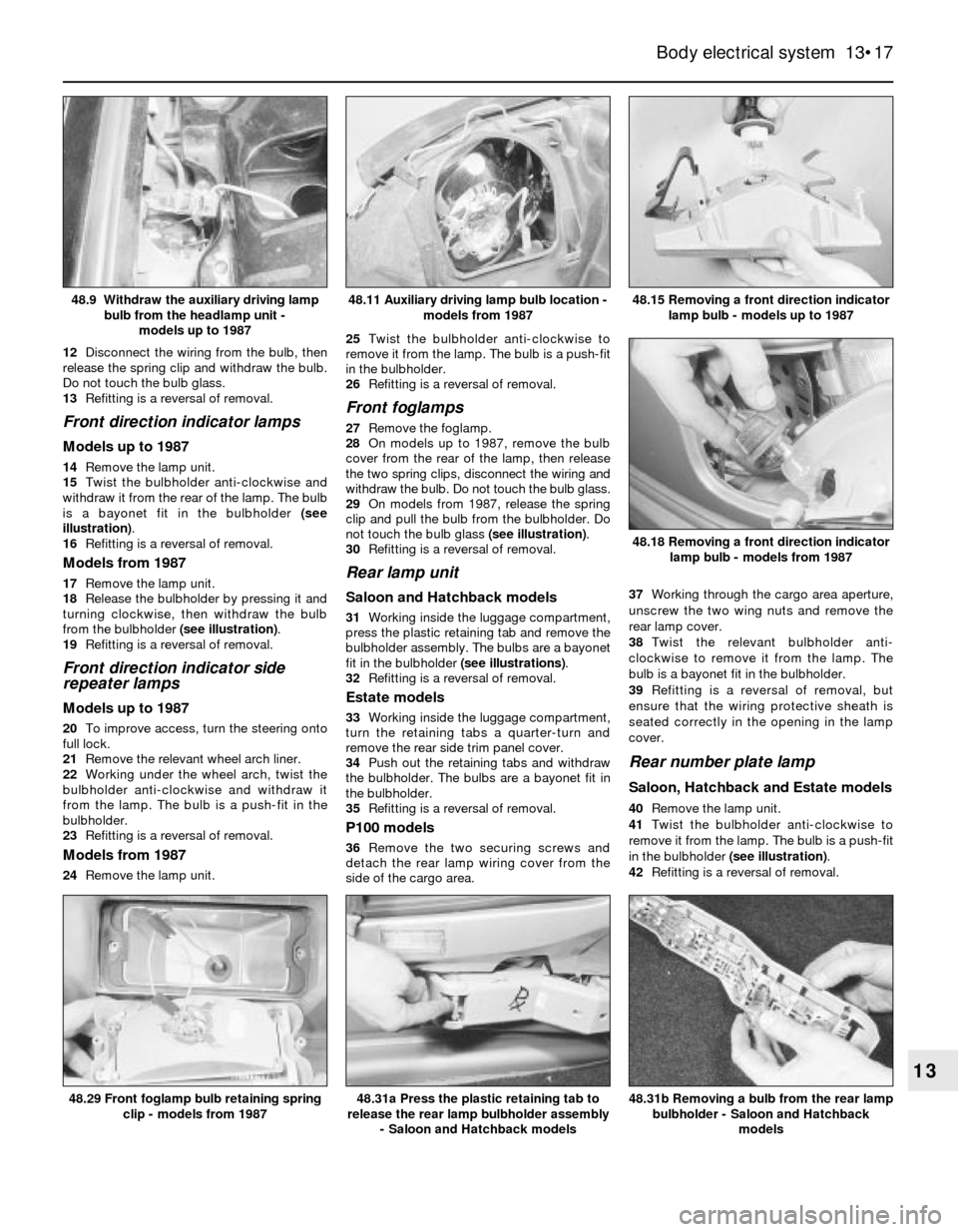
is a bayonet fit in the bulbholder (see
illustration).
16Refitting is a reversal of removal.
Models from 1987
17Remove the lamp unit.
18Release the bulbholder by pressing it and
turning clockwise, then withdraw the bulb
from the bulbholder (see illustration).
19Refitting is a reversal of removal.
Front direction indicator side
repeater lamps
Models up to 1987
20To improve access, turn the steering onto
full lock.
21Remove the relevant wheel arch liner.
22Working under the wheel arch, twist the
bulbholder anti-clockwise and withdraw it
from the lamp. The bulb is a push-fit in the
bulbholder.
23Refitting is a reversal of removal.
Models from 1987
24Remove the lamp unit. 25Twist the bulbholder anti-clockwise to
remove it from the lamp. The bulb is a push-fit
in the bulbholder.
26Refitting is a reversal of removal.
Front foglamps
27Remove the foglamp.
28On models up to 1987, remove the bulb
cover from the rear of the lamp, then release
the two spring clips, disconnect the wiring and
withdraw the bulb. Do not touch the bulb glass.
29On models from 1987, release the spring
clip and pull the bulb from the bulbholder. Do
not touch the bulb glass (see illustration).
30Refitting is a reversal of removal.
Rear lamp unit
Saloon and Hatchback models
31Working inside the luggage compartment,
press the plastic retaining tab and remove the
bulbholder assembly. The bulbs are a bayonet
fit in the bulbholder (see illustrations).
32Refitting is a reversal of removal.
Estate models
33Working inside the luggage compartment,
turn the retaining tabs a quarter-turn and
remove the rear side trim panel cover.
34Push out the retaining tabs and withdraw
the bulbholder. The bulbs are a bayonet fit in
the bulbholder.
35Refitting is a reversal of removal.
P100 models
36Remove the two securing screws and
detach the rear lamp wiring cover from the
side of the cargo area. 37Working through the cargo area aperture,
unscrew the two wing nuts and remove the
rear lamp cover.
38Twist the relevant bulbholder anti-
clockwise to remove it from the lamp. The
bulb is a bayonet fit in the bulbholder.
39Refitting is a reversal of removal, but
ensure that the wiring protective sheath is
seated correctly in the opening in the lamp
cover.
Rear number plate lamp
Saloon, Hatchback and Estate models
40Remove the lamp unit.
41Twist the bulbholder anti-clockwise to
remove it from the lamp. The bulb is a push-fit
in the bulbholder (see illustration).
42Refitting is a reversal of removal.
Body electrical system 13•17
13
48.15 Removing a front direction indicator
lamp bulb - models up to 1987
48.31b Removing a bulb from the rear lamp
bulbholder - Saloon and Hatchback
models48.31a Press the plastic retaining tab to
release the rear lamp bulbholder assembly
- Saloon and Hatchback models48.29 Front foglamp bulb retaining spring
clip - models from 1987
48.18 Removing a front direction indicator
lamp bulb - models from 1987
48.11 Auxiliary driving lamp bulb location -
models from 198748.9 Withdraw the auxiliary driving lamp
bulb from the headlamp unit -
models up to 1987