tow FORD SIERRA 1992 2.G Braking System Workshop Manual
[x] Cancel search | Manufacturer: FORD, Model Year: 1992, Model line: SIERRA, Model: FORD SIERRA 1992 2.GPages: 22, PDF Size: 1.11 MB
Page 6 of 22

1The shoe friction material can be inspected
for wear without removing the roadwheels.
Working beneath the vehicle, prise the plug
from the brake backplate, and using an
inspection lamp or torch, check that the
friction material thickness is not less than the
minimum given in the Specifications.
2If any one of the shoes has worn below the
specified limit, the shoes must be renewed as
an axle set (4 shoes).
3To renew the shoes, slacken the rear
roadwheel nuts, chock the front wheels, thenjack up the rear of the vehicle and support on
axle stands (see “Jacking and Vehicle
Support”).Remove the rear roadwheels, and
release the handbrake. On P100 models,
mark the position of the roadwheels in relation
to the brake drums before removal.
4Proceed as follows according to model:1.3 and 1.6 litre models
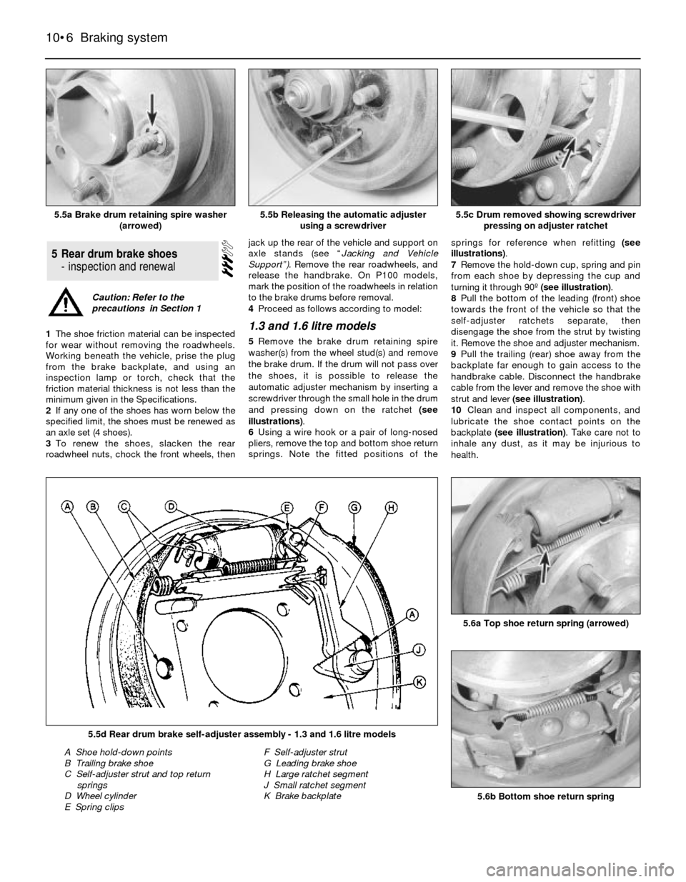
5Remove the brake drum retaining spire
washer(s) from the wheel stud(s) and remove
the brake drum. If the drum will not pass over
the shoes, it is possible to release the
automatic adjuster mechanism by inserting a
screwdriver through the small hole in the drum
and pressing down on the ratchet (see
illustrations).
6Using a wire hook or a pair of long-nosed
pliers, remove the top and bottom shoe return
springs. Note the fitted positions of thesprings for reference when refitting (see
illustrations).
7Remove the hold-down cup, spring and pin
from each shoe by depressing the cup and
turning it through 90º (see illustration).
8Pull the bottom of the leading (front) shoe
towards the front of the vehicle so that the
self-adjuster ratchets separate, then
disengage the shoe from the strut by twisting
it. Remove the shoe and adjuster mechanism.
9Pull the trailing (rear) shoe away from the
backplate far enough to gain access to the
handbrake cable. Disconnect the handbrake
cable from the lever and remove the shoe with
strut and lever (see illustration).
10Clean and inspect all components, and
lubricate the shoe contact points on the
backplate (see illustration). Take care not to
inhale any dust, as it may be injurious to
health.
5Rear drum brake shoes
- inspection and renewal
10•6Braking system
5.5a Brake drum retaining spire washer
(arrowed)5.5c Drum removed showing screwdriver
pressing on adjuster ratchet
5.6b Bottom shoe return spring
5.6a Top shoe return spring (arrowed)
5.5d Rear drum brake self-adjuster assembly - 1.3 and 1.6 litre models
A Shoe hold-down points
B Trailing brake shoe
C Self-adjuster strut and top return
springs
D Wheel cylinder
E Spring clipsF Self-adjuster strut
G Leading brake shoe
H Large ratchet segment
J Small ratchet segment
K Brake backplate
5.5b Releasing the automatic adjuster
using a screwdriver
Caution: Refer to the
precautions in Section 1
Page 8 of 22

27Unhook the return springs and remove the
leading shoe. Note the direction of wheel
rotation arrows on the shoes.
28Remove the hold-down cup, spring and
pin from the trailing (rear) shoe by depressing
the cup and turning it through 90º.
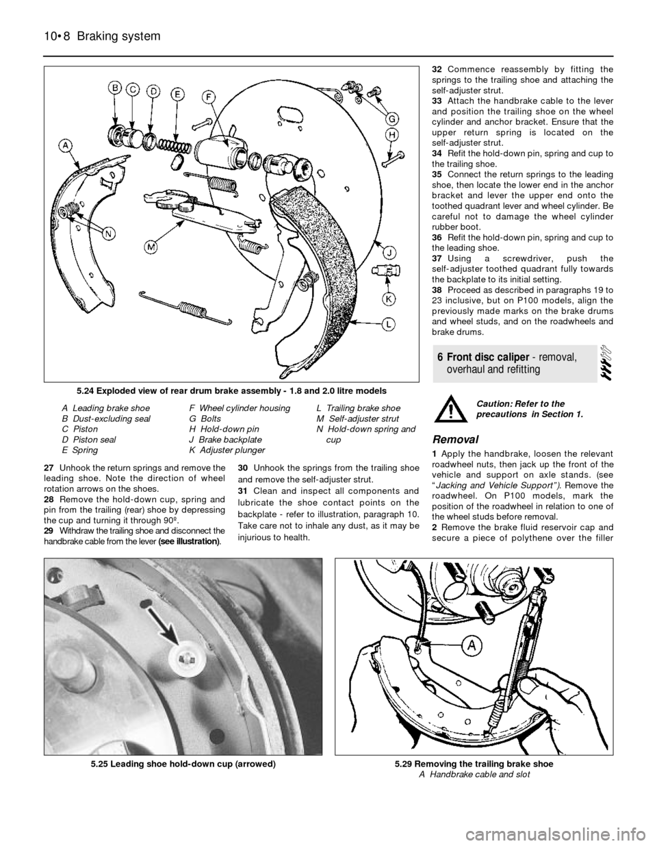
29Withdraw the trailing shoe and disconnect the
handbrake cable from the lever (see illustration).30Unhook the springs from the trailing shoe
and remove the self-adjuster strut.
31Clean and inspect all components and
lubricate the shoe contact points on the
backplate - refer to illustration, paragraph 10.
Take care not to inhale any dust, as it may be
injurious to health.32Commence reassembly by fitting the
springs to the trailing shoe and attaching the
self-adjuster strut.
33Attach the handbrake cable to the lever
and position the trailing shoe on the wheel
cylinder and anchor bracket. Ensure that the
upper return spring is located on the
self-adjuster strut.
34Refit the hold-down pin, spring and cup to
the trailing shoe.
35Connect the return springs to the leading
shoe, then locate the lower end in the anchor
bracket and lever the upper end onto the
toothed quadrant lever and wheel cylinder. Be
careful not to damage the wheel cylinder
rubber boot.
36Refit the hold-down pin, spring and cup to
the leading shoe.
37Using a screwdriver, push the
self-adjuster toothed quadrant fully towards
the backplate to its initial setting.
38Proceed as described in paragraphs 19 to
23 inclusive, but on P100 models, align the
previously made marks on the brake drums
and wheel studs, and on the roadwheels and
brake drums.
Removal
1Apply the handbrake, loosen the relevant
roadwheel nuts, then jack up the front of the
vehicle and support on axle stands. (see
“Jacking and Vehicle Support”). Remove the
roadwheel. On P100 models, mark the
position of the roadwheel in relation to one of
the wheel studs before removal.
2Remove the brake fluid reservoir cap and
secure a piece of polythene over the filler
6Front disc caliper - removal,
overhaul and refitting
10•8Braking system
5.24 Exploded view of rear drum brake assembly - 1.8 and 2.0 litre models
A Leading brake shoe
B Dust-excluding seal
C Piston
D Piston seal
E SpringF Wheel cylinder housing
G Bolts
H Hold-down pin
J Brake backplate
K Adjuster plungerL Trailing brake shoe
M Self-adjuster strut
N Hold-down spring and
cup
5.25 Leading shoe hold-down cup (arrowed)5.29 Removing the trailing brake shoe
A Handbrake cable and slot
Caution: Refer to the
precautions in Section 1.
Page 12 of 22

Specifications. To do this, fix the measuring
equipment, and rotate the disc, noting the
variation in measurement as the disc is
rotated. The difference between the minimum
and maximum measurements recorded is
known as disc run-out.
5Mark the position of the brake disc in
relation to the drive flange and on Saloon,
Hatchback and Estate models, remove the
retaining screw or spire washer(s), as
applicable, and remove the disc. On P100
models, also mark the position of the wheel
adapter plate in relation to the disc and drive
flange, then unscrew the five retaining nuts
and remove the wheel adapter plate and disc.
6Refitting is a reversal of removal, but when
refitting ensure that the mating faces of the
disc, drive flange and on P100 models the
wheel adapter plate, are clean. Align the
marks made on the disc, drive flange, and
where applicable the wheel adapter plate,
during removal. Refit the disc caliper and
carrier bracket.
Rear disc
7Chock the front wheels, loosen the relevant
roadwheel nuts, then jack up the rear of the
vehicle and support on axle stands.(see
“Jacking and Vehicle Support”).Remove the
roadwheel and release the handbrake.
8Detach the handbrake cable from the
retaining clip on the lower arm.
9Unscrew the two caliper carrier
bracket-to-hub carrier bolts and remove the
caliper assembly. Support the caliper on an
axle stand to avoid straining the flexible hose.
10Proceed as described in paragraphs 3
and 4.
11Mark the position of the brake disc in
relation to the drive flange, remove the
retaining spire washer(s), and withdraw the
disc.
12Refitting is a reversal of removal, but
ensure that the mating faces of the disc and
drive flanges are clean, and align the marks
made on the disc and drive flange during
removal.
1Whenever a brake drum is removed, brush
out the dust, taking care not to inhale any, as
it may be injurious to health.
2Examine the internal friction surface of the
drum. If deeply scored, or so worn that the
drum has become ridged to the width of the
shoes, then both drums must be renewed.
3Regrinding is not recommended as the
internal diameter of the drum will no longer be
compatible with the shoe friction material
contact diameter.
Saloon, Hatchback and Estate
models
1Chock the front wheels, loosen the relevant
roadwheel nuts, then jack up the rear of the
vehicle and support on axle stands (see
“Jacking and Vehicle Support”).Remove the
roadwheel and release the handbrake.
2Remove the retaining spire washer(s) from
the wheel stud(s) and pull off the brake drum.
If the drum will not pass over the shoes, it is
possible to release the automatic adjuster
mechanism by inserting a screwdriver through
the small hole in the drum and pressing down
on the ratchet.
3Remove the brake fluid reservoir cap and
secure a piece of polythene over the filler
neck with a rubber band, or by refitting the
cap. This will reduce the loss of fluid during
the following procedure.
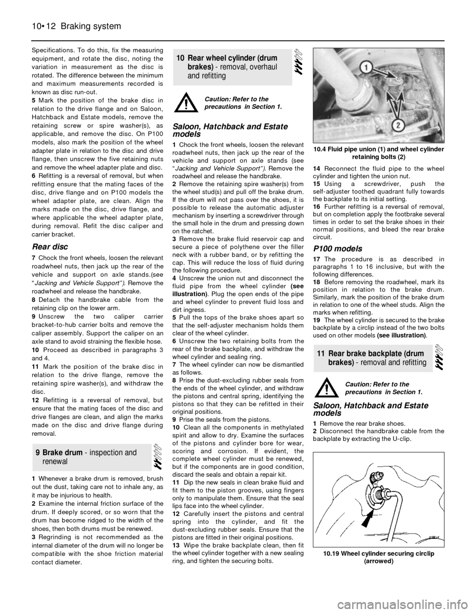
4Unscrew the union nut and disconnect the
fluid pipe from the wheel cylinder (see
illustration). Plug the open ends of the pipe
and wheel cylinder to prevent fluid loss and
dirt ingress.
5Pull the tops of the brake shoes apart so
that the self-adjuster mechanism holds them
clear of the wheel cylinder.
6Unscrew the two retaining bolts from the
rear of the brake backplate, and withdraw the
wheel cylinder and sealing ring.
7The wheel cylinder can now be dismantled
as follows.
8Prise the dust-excluding rubber seals from
the ends of the wheel cylinder, and withdraw
the pistons and central spring, identifying the
pistons so that they can be refitted in their
original positions.
9Prise the seals from the pistons.
10Clean all the components in methylated
spirit and allow to dry. Examine the surfaces
of the pistons and cylinder bore for wear,
scoring and corrosion. If evident, the
complete wheel cylinder must be renewed,
but if the components are in good condition,
discard the seals and obtain a repair kit.
11Dip the new seals in clean brake fluid and
fit them to the piston grooves, using fingers
only to manipulate them. Ensure that the seal
lips face into the wheel cylinder.
12Carefully insert the pistons and central
spring into the cylinder, and fit the
dust-excluding rubber seals. Ensure that the
pistons are fitted in their original positions.
13Wipe the brake backplate clean, then fit
the wheel cylinder together with a new sealing
ring, and tighten the securing bolts.14Reconnect the fluid pipe to the wheel
cylinder and tighten the union nut.
15Using a screwdriver, push the
self-adjuster toothed quadrant fully towards
the backplate to its initial setting.
16Further refitting is a reversal of removal,
but on completion apply the footbrake several
times in order to set the brake shoes in their
normal positions, and bleed the rear brake
circuit.
P100 models
17The procedure is as described in
paragraphs 1 to 16 inclusive, but with the
following differences.
18Before removing the roadwheel, mark its
position in relation to the brake drum.
Similarly, mark the position of the brake drum
in relation to one of the wheel studs. Align the
marks when refitting.
19The wheel cylinder is secured to the brake
backplate by a circlip instead of the two bolts
used on other models (see illustration).
Saloon, Hatchback and Estate
models
1Remove the rear brake shoes.
2Disconnect the handbrake cable from the
backplate by extracting the U-clip.
11Rear brake backplate (drum
brakes) - removal and refitting
10Rear wheel cylinder (drum
brakes) -removal,overhaul
andrefitting
9Brake drum -inspectionand
renewal
10•12Braking system
10.4 Fluid pipe union (1) and wheel cylinder
retaining bolts (2)
10.19 Wheel cylinder securing circlip
(arrowed)
Caution: Refer to the
precautions in Section 1.
Caution: Refer to the
precautions in Section 1.