fuel type FORD SIERRA 1992 2.G Engine Electrical Systems User Guide
[x] Cancel search | Manufacturer: FORD, Model Year: 1992, Model line: SIERRA, Model: FORD SIERRA 1992 2.GPages: 24, PDF Size: 0.93 MB
Page 13 of 24
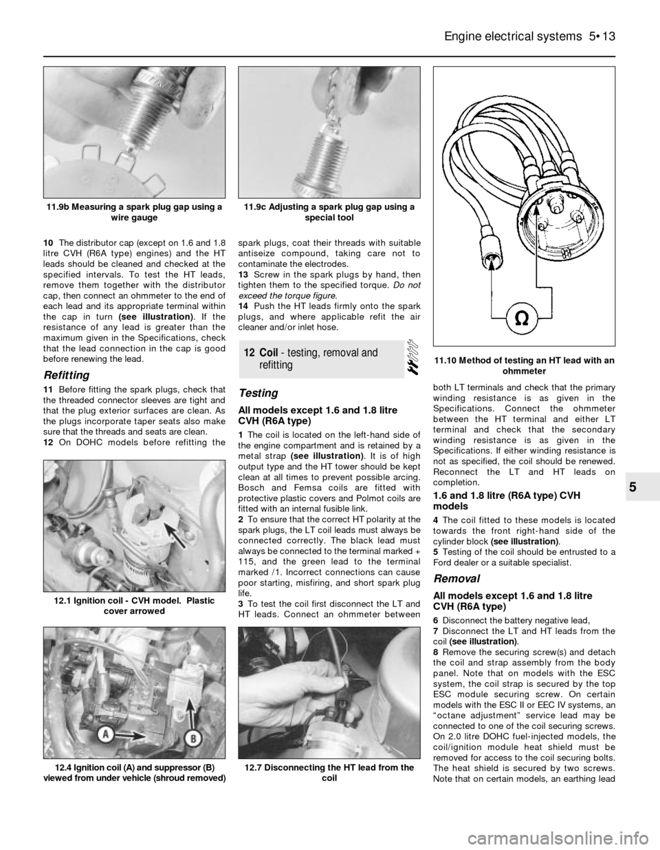
10The distributor cap (except on 1.6 and 1.8
litre CVH (R6A type) engines) and the HT
leads should be cleaned and checked at the
specified intervals. To test the HT leads,
remove them together with the distributor
cap, then connect an ohmmeter to the end of
each lead and its appropriate terminal within
the cap in turn (see illustration). If the
resistance of any lead is greater than the
maximum given in the Specifications, check
that the lead connection in the cap is good
before renewing the lead.
Refitting
11Before fitting the spark plugs, check that
the threaded connector sleeves are tight and
that the plug exterior surfaces are clean. As
the plugs incorporate taper seats also make
sure that the threads and seats are clean.
12On DOHC models before refitting thespark plugs, coat their threads with suitable
antiseize compound, taking care not to
contaminate the electrodes.
13Screw in the spark plugs by hand, then
tighten them to the specified torque. Do not
exceed the torque figure.
14Push the HT leads firmly onto the spark
plugs, and where applicable refit the air
cleaner and/or inlet hose.Testing
All models except 1.6 and 1.8 litre
CVH (R6A type)
1The coil is located on the left-hand side of
the engine compartment and is retained by a
metal strap (see illustration). It is of high
output type and the HT tower should be kept
clean at all times to prevent possible arcing.
Bosch and Femsa coils are fitted with
protective plastic covers and Polmot coils are
fitted with an internal fusible link.
2To ensure that the correct HT polarity at the
spark plugs, the LT coil leads must always be
connected correctly. The black lead must
always be connected to the terminal marked +
115, and the green lead to the terminal
marked /1. Incorrect connections can cause
poor starting, misfiring, and short spark plug
life.
3To test the coil first disconnect the LT and
HT leads. Connect an ohmmeter betweenboth LT terminals and check that the primary
winding resistance is as given in the
Specifications. Connect the ohmmeter
between the HT terminal and either LT
terminal and check that the secondary
winding resistance is as given in the
Specifications. If either winding resistance is
not as specified, the coil should be renewed.
Reconnect the LT and HT leads on
completion.
1.6 and 1.8 litre (R6A type) CVH
models
4The coil fitted to these models is located
towards the front right-hand side of the
cylinder block (see illustration).
5Testing of the coil should be entrusted to a
Ford dealer or a suitable specialist.
Removal
All models except 1.6 and 1.8 litre
CVH (R6A type)
6Disconnect the battery negative lead,
7Disconnect the LT and HT leads from the
coil (see illustration).
8Remove the securing screw(s) and detach
the coil and strap assembly from the body
panel. Note that on models with the ESC
system, the coil strap is secured by the top
ESC module securing screw. On certain
models with the ESC II or EEC IV systems, an
“octane adjustment” service lead may be
connected to one of the coil securing screws.
On 2.0 litre DOHC fuel-injected models, the
coil/ignition module heat shield must be
removed for access to the coil securing bolts.
The heat shield is secured by two screws.
Note that on certain models, an earthing lead
12Coil - testing, removal and
refitting
Engine electrical systems 5•13
5
11.10 Method of testing an HT lead with an
ohmmeter
12.4 Ignition coil (A) and suppressor (B)
viewed from under vehicle (shroud removed)12.7 Disconnecting the HT lead from the
coil
12.1 Ignition coil - CVH model. Plastic
cover arrowed
11.9c Adjusting a spark plug gap using a
special tool11.9b Measuring a spark plug gap using a
wire gauge
Page 14 of 24
and/or a suppressor may be secured by one
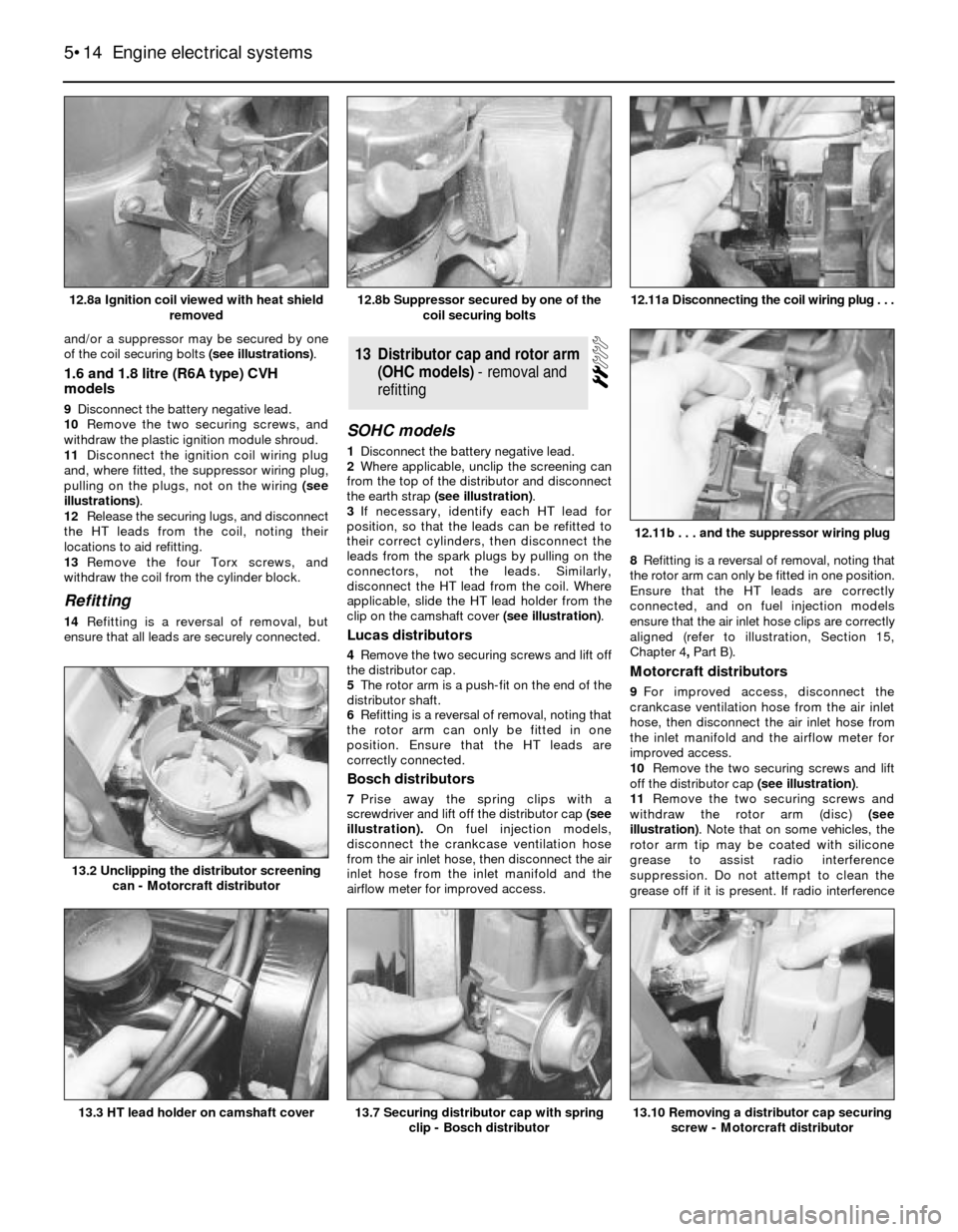
of the coil securing bolts (see illustrations).
1.6 and 1.8 litre (R6A type) CVH
models
9Disconnect the battery negative lead.
10Remove the two securing screws, and
withdraw the plastic ignition module shroud.
11Disconnect the ignition coil wiring plug
and, where fitted, the suppressor wiring plug,
pulling on the plugs, not on the wiring (see
illustrations).
12Release the securing lugs, and disconnect
the HT leads from the coil, noting their
locations to aid refitting.
13Remove the four Torx screws, and
withdraw the coil from the cylinder block.
Refitting
14Refitting is a reversal of removal, but
ensure that all leads are securely connected.
SOHC models
1Disconnect the battery negative lead.
2Where applicable, unclip the screening can
from the top of the distributor and disconnect
the earth strap (see illustration).
3If necessary, identify each HT lead for
position, so that the leads can be refitted to
their correct cylinders, then disconnect the
leads from the spark plugs by pulling on the
connectors, not the leads. Similarly,
disconnect the HT lead from the coil. Where
applicable, slide the HT lead holder from the
clip on the camshaft cover (see illustration).
Lucas distributors
4Remove the two securing screws and lift off
the distributor cap.
5The rotor arm is a push-fit on the end of the
distributor shaft.
6Refitting is a reversal of removal, noting that
the rotor arm can only be fitted in one
position. Ensure that the HT leads are
correctly connected.
Bosch distributors
7Prise away the spring clips with a
screwdriver and lift off the distributor cap(see
illustration).On fuel injection models,
disconnect the crankcase ventilation hose
from the air inlet hose, then disconnect the air
inlet hose from the inlet manifold and the
airflow meter for improved access. 8Refitting is a reversal of removal, noting that
the rotor arm can only be fitted in one position.
Ensure that the HT leads are correctly
connected, and on fuel injection models
ensure that the air inlet hose clips are correctly
aligned (refer to illustration, Section 15,
Chapter 4, PartB).
Motorcraft distributors
9For improved access, disconnect the
crankcase ventilation hose from the air inlet
hose, then disconnect the air inlet hose from
the inlet manifold and the airflow meter for
improved access.
10Remove the two securing screws and lift
off the distributor cap (see illustration).
11Remove the two securing screws and
withdraw the rotor arm (disc) (see
illustration). Note that on some vehicles, the
rotor arm tip may be coated with silicone
grease to assist radio interference
suppression. Do not attempt to clean the
grease off if it is present. If radio interference
13Distributor cap and rotor arm
(OHC models) - removal and
refitting
5•14Engine electrical systems
12.8a Ignition coil viewed with heat shield
removed12.11a Disconnecting the coil wiring plug . . .
13.10 Removing a distributor cap securing
screw - Motorcraft distributor13.7 Securing distributor cap with spring
clip - Bosch distributor13.3 HT lead holder on camshaft cover
13.2 Unclipping the distributor screening
can - Motorcraft distributor
12.11b . . . and the suppressor wiring plug
12.8b Suppressor secured by one of the
coil securing bolts
Page 17 of 24
Refitting
13Commence refitting by checking that No 1
cylinder is still at the firing point. The relevant
timing marks should be aligned. If the engine
has been turned whilst the distributor has
been removed, check that No 1 cylinder is on
its firing stroke by removing the No 1 cylinder
spark plug and placing a finger over the plug
hole. Turn the crankshaft until compression
can be felt, which indicates that No 1 piston is
rising on its firing stroke. Continue turning the
crankshaft until the relevant timing marks are
in alignment.
14Turn the rotor arm to the position noted in
paragraph 11. If a new distributor is being
fitted, and no alignment marks are present,
transfer the marks from the old distributor to
the new distributor.
15Hold the distributor directly over the
aperture in the cylinder block with the
previously made marks on the distributor
body and cylinder block aligned, then lower
the distributor into position. Again, if a new
distributor is being fitted, transfer the
alignment mark from the old distributor body
to the new distributor body. As the skew gear
drive meshes, the rotor arm will turn
anti-clockwise.
16With the distributor fitted and the marks
on the distributor body and cylinder block
aligned, check that the rotor arm is positioned
as described in paragraph 7 -if not, withdraw
the distributor, re-position the driveshaft and
try again.
17Refit the clamp, then insert and tighten
the bolt. Do not fully tighten the bolt at this
stage.
18Refit the distributor wiring plug, and
where applicable reconnect the vacuum pipe,
and refit the dust cover and/or rotor arm.
19Refit the distributor cap, and reconnect
the HT leads to the spark plugs and coil.
Ensure that the leads are refitted to their
correct cylinders.
20Where applicable, refit the screening can
to the top of the distributor and reconnect the
earth strap. On fuel injection models,
reconnect the air inlet hose, ensuring that the
clips are correctly aligned (refer to illustration,
Section 15, Chapter 4, PartB).21Reconnect the battery negative lead.
22Check and if necessary adjust the ignition
timing.
Early “Economy” models
Removal
23Removal of the distributor fitted to these
models is a similar process to that described
above.
Refitting
24Turn the crankshaft to bring No 1 cylinder
to the firing point, with the 16º BTDC mark on
the crankshaft pulley aligned with the pointer
on the crankshaft front oil seal housing, as
described above.
25Fit the new distributor to the engine as
described above, then proceed as follows.
26Cut the original distributor wiring plug
from the wiring loom. Make the cut close to
the connector.
27Strip back 10 mm of insulation from each
of the wires on the wiring loom, and on the
adapter loom supplied with the new
distributor.
28Solder the adapter loom wires to the
corresponding identically coloured wires in
the main loom.
29Carefully insulate each individual soldered
joint using insulating tape, then apply tape to
cover the join between the looms.
30Fit a new distributor cap (and screening
can, where applicable), and connect the HT
leads.31Connect the adapter loom to the
distributor.
32Start the engine, and adjust the ignition
timing to the value given in the Specifications
at the beginning of this Chapter. Work as
described above whilst noting that the
vacuum pipe must be left connected.
Note: During production the ignition timing is
accurately set using a microwave process,
and sealant is applied to the distributor clamp
bolt. Because the electronic components
require no maintenance, checking the ignition
timing does not constitute part of the routine
maintenance schedule, and the procedure is
therefore only necessary after removal and
refitting of the distributor. A timing light will be
required for this procedure. For details of
ignition timing adjustment in order to operate
vehicles on unleaded petrol refer to the
appropriate Section of this Chapter.
All models except 2.0 litre DOHC
1Before checking the ignition timing, the
following conditions must be met:
a)The engine must be at normal operating
temperature
b)Where applicable, the vacuum pipe to the
distributor vacuum unit or electronic
module (as applicable) must be
disconnected from the vacuum unit or
electronic module and plugged
c)The idle speed must be below 900 rpm
(isolate “idle speed adjustment” wire if
necessary)
d)Any earthed “octane adjustment” wires
must be temporarily isolated
2Wipe clean the crankshaft pulley timing
marks and the pointer on the crankshaft front
oil seal housing. Note that two alternative
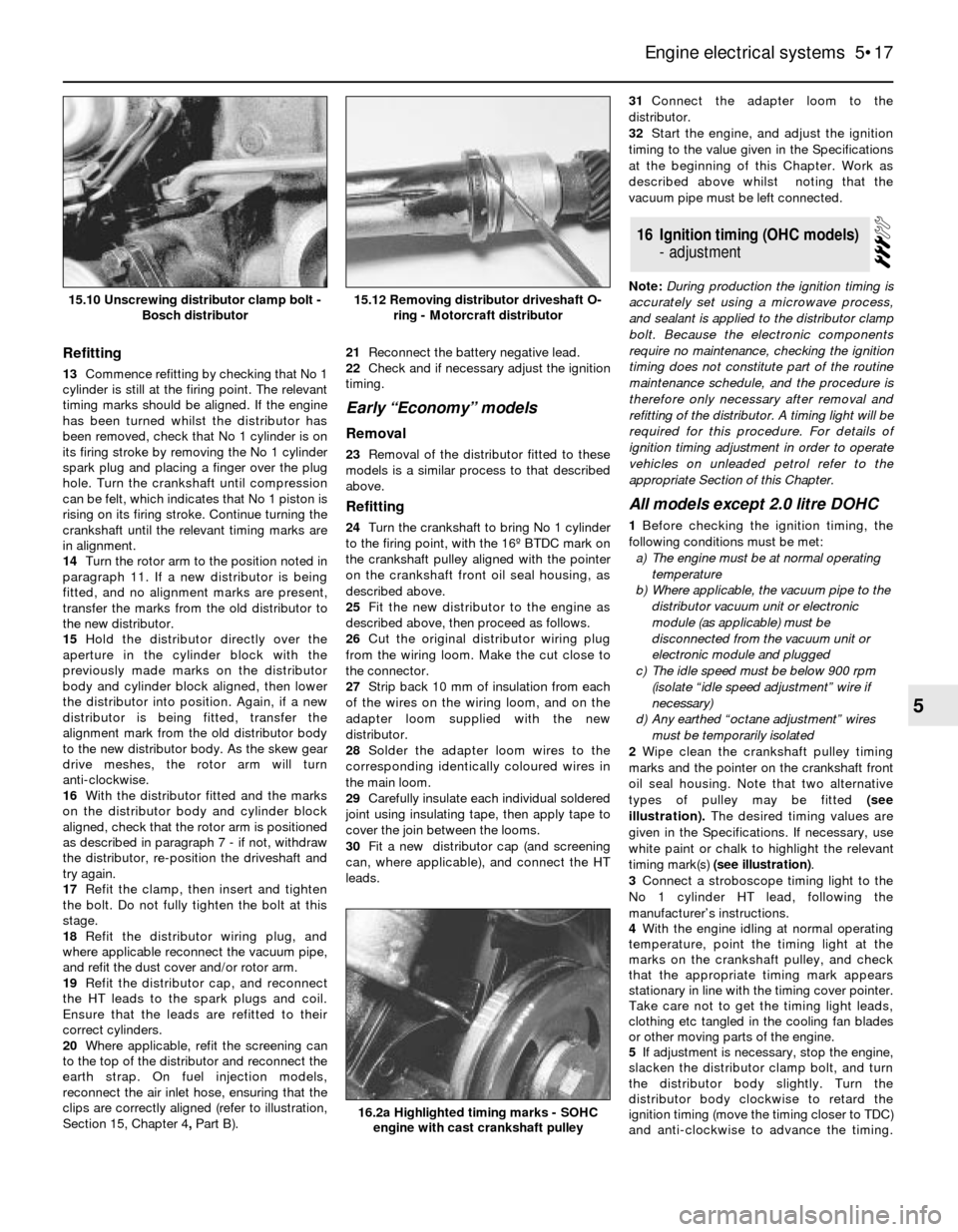
types of pulley may be fitted (see
illustration).The desired timing values are
given in the Specifications. If necessary, use
white paint or chalk to highlight the relevant
timing mark(s) (see illustration).
3Connect a stroboscope timing light to the
No 1 cylinder HT lead, following the
manufacturer’s instructions.
4With the engine idling at normal operating
temperature, point the timing light at the
marks on the crankshaft pulley, and check
that the appropriate timing mark appears
stationary in line with the timing cover pointer.
Take care not to get the timing light leads,
clothing etc tangled in the cooling fan blades
or other moving parts of the engine.
5If adjustment is necessary, stop the engine,
slacken the distributor clamp bolt, and turn
the distributor body slightly. Turn the
distributor body clockwise to retard the
ignition timing (move the timing closer to TDC)
and anti-clockwise to advance the timing.
16Ignition timing (OHC models)
- adjustment
Engine electrical systems 5•17
5
15.12 Removing distributor driveshaft O-
ring - Motorcraft distributor15.10 Unscrewing distributor clamp bolt -
Bosch distributor
16.2a Highlighted timing marks - SOHC
engine with cast crankshaft pulley
Page 18 of 24
Note that the required distributor body
movement will be half of the required
crankshaft movement (ie an adjustment of 5º
in ignition timing will require the distributor
body to be turned 2º. Tighten the clamp bolt
and re-check the timing.
6On models with inductive discharge ignition
systems, the mechanical and vacuum
advance mechanisms can be checked as
follows. On all other models, proceed to
paragraph 10.
7With the engine idling, timing light
connected, and vacuum pipe disconnected as
described in the preceding paragraphs,
increase the engine speed to approximately
2000 rpm (if desired, connect a tachometer to
the engine in accordance with the
manufacturer”s instructions). Note the
approximate distance which the relevant pulley
mark moves out of alignment with the pointer.
8Reconnect the vacuum pipe to the
distributor or electronic module, as
applicable, and repeat the procedure given in
the previous paragraph, when for the same
increase in engine speed, the alignment
differential between the pulley mark and
pointer should be greater than previously
observed.
9If the pulley mark does not appear to move
during the first part of the check, a fault in the
distributor mechanical advance mechanism is
indicated. No increased movement of the
mark during the second part of the check
indicates a punctured diaphragm in the
distributor vacuum unit, or a leak in the
vacuum line.
10On completion of the adjustments and
checks, stop the engine and disconnect the
timing light. Where applicable, reconnect the
vacuum pipe, if not already done, and
reconnect any “octane adjustment” and “idle
speed adjustment” wires. Make a final check
to ensure that the distributor clamp bolt is
tight.
11Finally, the idle speed and mixture should
be checked and adjusted.2.0 litre DOHC carburettor model
12The ignition timing is controlled by the
ESC II module, and no adjustment is possible.
2.0 litre DOHC fuel injection
model
13The ignition timing is controlled by the
EEC IV module, and no adjustment is
possible.
Note: Refer to the Specifications Section at
the beginning of this Chapter for ignition
timing values for use with unleaded petrol.
1To run an engine on unleaded petrol,
certain criteria must be met, and it may be
helpful to first describe the various terms used
for the different types of petrol:
Normal leaded petrol (4-star, 97 RON):
Petrol which has a low amount of lead added
during manufacture (0.15 g/litre), in addition to
the natural lead found in crude oil.
Unleaded petrol (Premium, 95 RON):
Has no lead added during manufacture, but
still has the natural lead content of crude oil.
Lead free petrol: Contains no lead. It has
no lead added during manufacture, and the
natural lead content is refined out. This
type of petrol is not currently available for
general use in the UK and should not be
confused with unleaded petrol.
2To run an engine continuously on unleaded
petrol, suitable hardened valve seat inserts
must be fitted to the cylinder head.
3The OHC engines fitted to the Sierra/P100
range which have suitable valve seat inserts
fitted at manufacture can be identified by
letters stamped on the cylinder head next to
No 4 spark plug as follows:
1.6 litre enginesM, MM, N, or NN
1.6 litre enginesS or SS
2.0 litre enginesL, P, PP, R, or RR4All CVH engines have suitable valve seat
inserts fitted.
5Vehicles which have no identification letter
stamped on the cylinder head, and are not
fitted with suitable valve seat inserts, may still
be run on unleaded petrol (although
continuous use is not recommended),
provided that every fourth tank filling is of
normal leaded petrol, ie: three tanks of
unleaded petrol followed by one tank of
normal leaded petrol.
6When running an OHC engine on unleaded
petrol (Premium, 95 RON), the ignition timing
must be retarded as described in the
following sub-Sections. There is no
requirement for ignition timing adjustment
when running CVH engines on unleaded
petrol.
Inductive discharge ignition
system and ESC system
7On vehicles fitted with an inductive
discharge ignition system, or the ESC system,
the ignition timing should be retarded as
specified.
ESC II and EEC IV systems
8On vehicles fitted with the ESC II or EEC IV
systems, there is a facility for retarding the
ignition timing without physically disturbing
the distributor.
9Adjustment is made by earthing one or two
wires (“octane adjustment” wires) which
terminate in a wiring plug next to the ignition
coil. Ideally a service adjustment lead,
available from a Ford dealer should be used
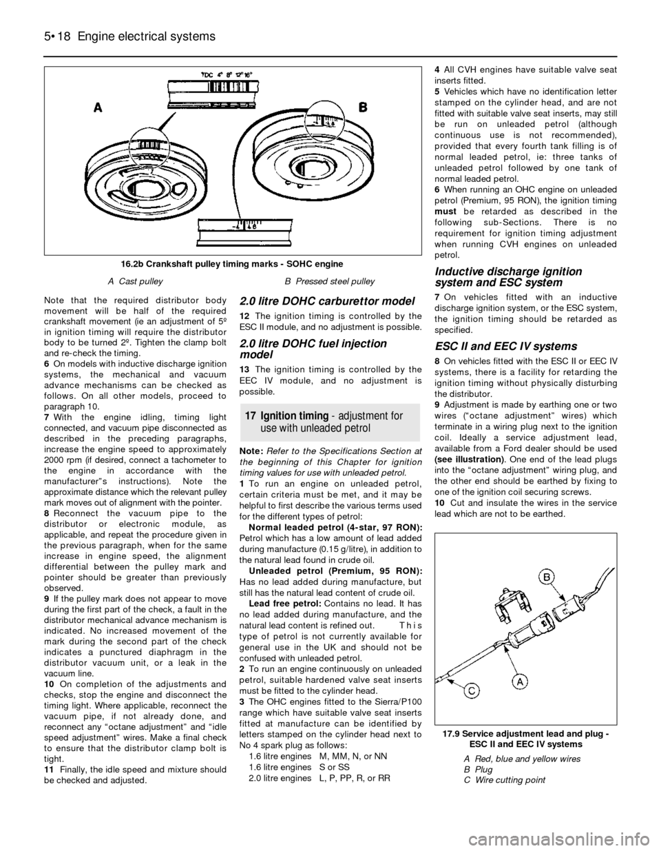
(see illustration). One end of the lead plugs
into the “octane adjustment” wiring plug, and
the other end should be earthed by fixing to
one of the ignition coil securing screws.
10Cut and insulate the wires in the service
lead which are not to be earthed.
17Ignition timing -adjustmentfor
usewithunleadedpetrol
5•18Engine electrical systems
17.9 Service adjustment lead and plug -
ESC II and EEC IV systems
A Red, blue and yellow wires
B Plug
C Wire cutting point
16.2b Crankshaft pulley timing marks - SOHC engine
A Cast pulleyB Pressed steel pulley
Page 20 of 24
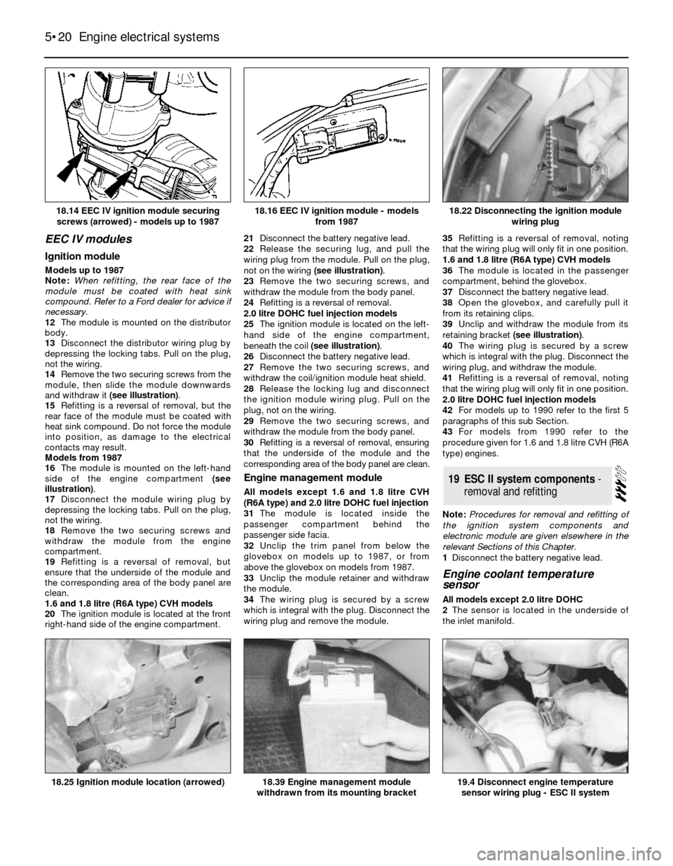
EEC IV modules
Ignition module
Models up to 1987
Note: When refitting, the rear face of the
module must be coated with heat sink
compound. Refer to a Ford dealer for advice if
necessary.
12The module is mounted on the distributor
body.
13Disconnect the distributor wiring plug by
depressing the locking tabs. Pull on the plug,
not the wiring.
14Remove the two securing screws from the
module, then slide the module downwards
and withdraw it (see illustration).
15Refitting is a reversal of removal, but the
rear face of the module must be coated with
heat sink compound. Do not force the module
into position, as damage to the electrical
contacts may result.
Models from 1987
16The module is mounted on the left-hand
side of the engine compartment (see
illustration).
17Disconnect the module wiring plug by
depressing the locking tabs. Pull on the plug,
not the wiring.
18Remove the two securing screws and
withdraw the module from the engine
compartment.
19Refitting is a reversal of removal, but
ensure that the underside of the module and
the corresponding area of the body panel are
clean.
1.6 and 1.8 litre (R6A type) CVH models
20The ignition module is located at the front
right-hand side of the engine compartment. 21Disconnect the battery negative lead.
22Release the securing lug, and pull the
wiring plug from the module. Pull on the plug,
not on the wiring (see illustration).
23Remove the two securing screws, and
withdraw the module from the body panel.
24Refitting is a reversal of removal.
2.0 litre DOHC fuel injection models
25The ignition module is located on the left-
hand side of the engine compartment,
beneath the coil (see illustration).
26Disconnect the battery negative lead.
27Remove the two securing screws, and
withdraw the coil/ignition module heat shield.
28Release the locking lug and disconnect
the ignition module wiring plug. Pull on the
plug, not on the wiring.
29Remove the two securing screws, and
withdraw the module from the body panel.
30Refitting is a reversal of removal, ensuring
that the underside of the module and the
corresponding area of the body panel are clean.
Engine management module
All models except 1.6 and 1.8 litre CVH
(R6A type) and 2.0 litre DOHC fuel injection
31The module is located inside the
passenger compartment behind the
passenger side facia.
32Unclip the trim panel from below the
glovebox on models up to 1987, or from
above the glovebox on models from 1987.
33Unclip the module retainer and withdraw
the module.
34The wiring plug is secured by a screw
which is integral with the plug. Disconnect the
wiring plug and remove the module.35Refitting is a reversal of removal, noting
that the wiring plug will only fit in one position.
1.6 and 1.8 litre (R6A type) CVH models
36The module is located in the passenger
compartment, behind the glovebox.
37Disconnect the battery negative lead.
38Open the glovebox, and carefully pull it
from its retaining clips.
39Unclip and withdraw the module from its
retaining bracket (see illustration).
40The wiring plug is secured by a screw
which is integral with the plug. Disconnect the
wiring plug, and withdraw the module.
41Refitting is a reversal of removal, noting
that the wiring plug will only fit in one position.
2.0 litre DOHC fuel injection models
42For models up to 1990 refer to the first 5
paragraphs of this sub Section.
43For models from 1990 refer to the
procedure given for 1.6 and 1.8 litre CVH (R6A
type) engines.
Note: Procedures for removal and refitting of
the ignition system components and
electronic module are given elsewhere in the
relevant Sections of this Chapter.
1Disconnect the battery negative lead.
Engine coolant temperature
sensor
All models except 2.0 litre DOHC
2The sensor is located in the underside of
the inlet manifold.
19ESC II system components -
removal and refitting
5•20Engine electrical systems
18.14 EEC IV ignition module securing
screws (arrowed) - models up to 198718.22 Disconnecting the ignition module
wiring plug
19.4 Disconnect engine temperature
sensor wiring plug - ESC II system18.39 Engine management module
withdrawn from its mounting bracket18.25 Ignition module location (arrowed)
18.16 EEC IV ignition module - models
from 1987
Page 23 of 24
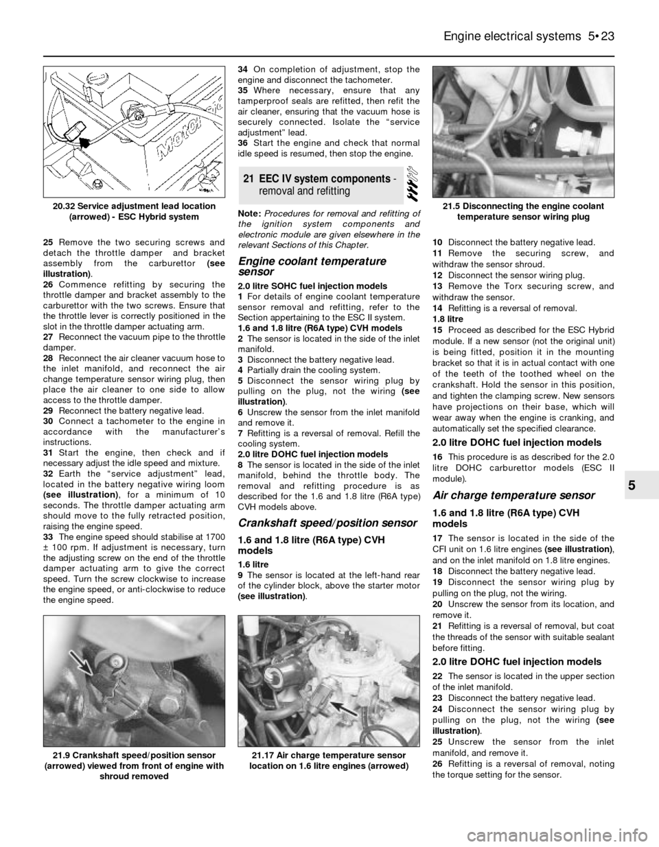
25Remove the two securing screws and
detach the throttle damper and bracket
assembly from the carburettor (see
illustration).
26Commence refitting by securing the
throttle damper and bracket assembly to the
carburettor with the two screws. Ensure that
the throttle lever is correctly positioned in the
slot in the throttle damper actuating arm.
27Reconnect the vacuum pipe to the throttle
damper.
28Reconnect the air cleaner vacuum hose to
the inlet manifold, and reconnect the air
change temperature sensor wiring plug, then
place the air cleaner to one side to allow
access to the throttle damper.
29Reconnect the battery negative lead.
30Connect a tachometer to the engine in
accordance with the manufacturer’s
instructions.
31Start the engine, then check and if
necessary adjust the idle speed and mixture.
32Earth the “service adjustment” lead,
located in the battery negative wiring loom
(see illustration), for a minimum of 10
seconds. The throttle damper actuating arm
should move to the fully retracted position,
raising the engine speed.
33The engine speed should stabilise at 1700
±100 rpm. If adjustment is necessary, turn
the adjusting screw on the end of the throttle
damper actuating arm to give the correct
speed. Turn the screw clockwise to increase
the engine speed, or anti-clockwise to reduce
the engine speed.34On completion of adjustment, stop the
engine and disconnect the tachometer.
35Where necessary, ensure that any
tamperproof seals are refitted, then refit the
air cleaner, ensuring that the vacuum hose is
securely connected. Isolate the “service
adjustment” lead.
36Start the engine and check that normal
idle speed is resumed, then stop the engine.
Note:Procedures for removal and refitting of
the ignition system components and
electronic module are given elsewhere in the
relevant Sections of this Chapter.
Engine coolant temperature
sensor
2.0 litre SOHC fuel injection models
1For details of engine coolant temperature
sensor removal and refitting, refer to the
Section appertaining to the ESC II system.
1.6 and 1.8 litre (R6A type) CVH models
2The sensor is located in the side of the inlet
manifold.
3Disconnect the battery negative lead.
4Partially drain the cooling system.
5Disconnect the sensor wiring plug by
pulling on the plug, not the wiring (see
illustration).
6Unscrew the sensor from the inlet manifold
and remove it.
7Refitting is a reversal of removal. Refill the
cooling system.
2.0 litre DOHC fuel injection models
8The sensor is located in the side of the inlet
manifold, behind the throttle body. The
removal and refitting procedure is as
described for the 1.6 and 1.8 litre (R6A type)
CVH models above.
Crankshaft speed/position sensor
1.6 and 1.8 litre (R6A type) CVH
models
1.6 litre
9The sensor is located at the left-hand rear
of the cylinder block, above the starter motor
(see illustration).10Disconnect the battery negative lead.
11Remove the securing screw, and
withdraw the sensor shroud.
12Disconnect the sensor wiring plug.
13Remove the Torx securing screw, and
withdraw the sensor.
14Refitting is a reversal of removal.
1.8 litre
15Proceed as described for the ESC Hybrid
module. If a new sensor (not the original unit)
is being fitted, position it in the mounting
bracket so that it is in actual contact with one
of the teeth of the toothed wheel on the
crankshaft. Hold the sensor in this position,
and tighten the clamping screw. New sensors
have projections on their base, which will
wear away when the engine is cranking, and
automatically set the specified clearance.
2.0 litre DOHC fuel injection models
16This procedure is as described for the 2.0
litre DOHC carburettor models (ESC II
module).
Air charge temperature sensor
1.6 and 1.8 litre (R6A type) CVH
models
17The sensor is located in the side of the
CFI unit on 1.6 litre engines (see illustration),
and on the inlet manifold on 1.8 litre engines.
18Disconnect the battery negative lead.
19Disconnect the sensor wiring plug by
pulling on the plug, not the wiring.
20Unscrew the sensor from its location, and
remove it.
21Refitting is a reversal of removal, but coat
the threads of the sensor with suitable sealant
before fitting.
2.0 litre DOHC fuel injection models
22The sensor is located in the upper section
of the inlet manifold.
23Disconnect the battery negative lead.
24Disconnect the sensor wiring plug by
pulling on the plug, not the wiring (see
illustration).
25Unscrew the sensor from the inlet
manifold, and remove it.
26Refitting is a reversal of removal, noting
the torque setting for the sensor.
21EEC IV system components -
removaland refitting
Engine electrical systems 5•23
5
21.9 Crankshaft speed/position sensor
(arrowed) viewed from front of engine with
shroud removed21.17 Air charge temperature sensor
location on 1.6 litre engines (arrowed)
21.5 Disconnecting the engine coolant
temperature sensor wiring plug20.32 Service adjustment lead location
(arrowed) - ESC Hybrid system
Page 24 of 24
Vehicle speed sensor
1.6 and 1.8 litre CVH (R6A type) and
2.0 litre DOHC fuel injection models
27The sensor is located in the left-hand side
of the gearbox/transmission.
28Disconnect the battery negative lead.
29Jack up the vehicle and support it
securely on axle stands (see “Jacking and
Vehicle Support”).
30Detach the sensor wiring connector from
its bracket, and separate the two halves of the
connector.
31Unscrew the securing bolt, and withdraw
the wiring connector bracket, noting its
orientation.
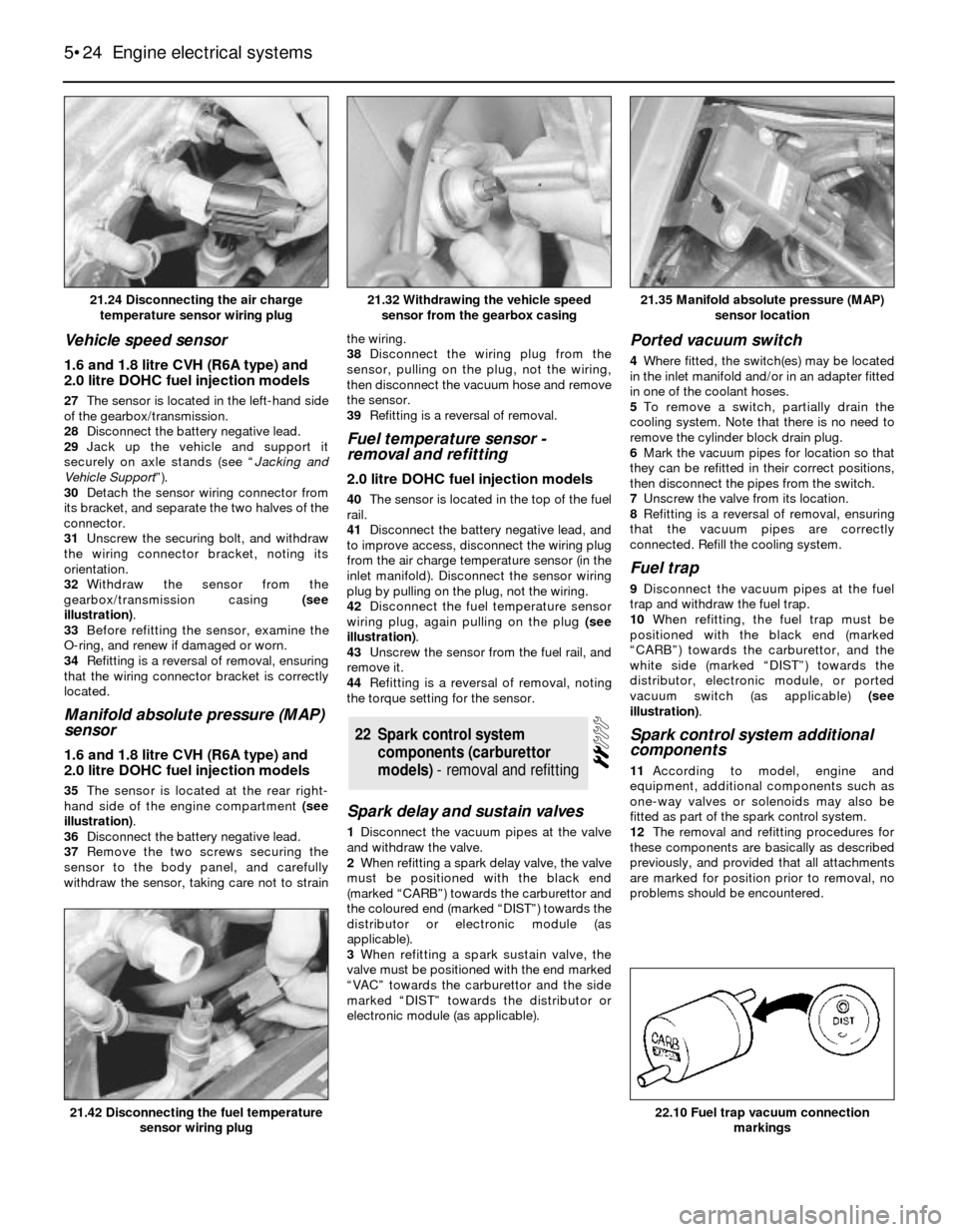
32Withdraw the sensor from the
gearbox/transmission casing (see
illustration).
33Before refitting the sensor, examine the
O-ring, and renew if damaged or worn.
34Refitting is a reversal of removal, ensuring
that the wiring connector bracket is correctly
located.
Manifold absolute pressure (MAP)
sensor
1.6 and 1.8 litre CVH (R6A type) and
2.0 litre DOHC fuel injection models
35The sensor is located at the rear right-
hand side of the engine compartment (see
illustration).
36Disconnect the battery negative lead.
37Remove the two screws securing the
sensor to the body panel, and carefully
withdraw the sensor, taking care not to strainthe wiring.
38Disconnect the wiring plug from the
sensor, pulling on the plug, not the wiring,
then disconnect the vacuum hose and remove
the sensor.
39Refitting is a reversal of removal.
Fuel temperature sensor -
removal and refitting
2.0 litre DOHC fuel injection models
40The sensor is located in the top of the fuel
rail.
41Disconnect the battery negative lead, and
to improve access, disconnect the wiring plug
from the air charge temperature sensor (in the
inlet manifold). Disconnect the sensor wiring
plug by pulling on the plug, not the wiring.
42Disconnect the fuel temperature sensor
wiring plug, again pulling on the plug (see
illustration).
43Unscrew the sensor from the fuel rail, and
remove it.
44Refitting is a reversal of removal, noting
the torque setting for the sensor.
Spark delay and sustain valves
1Disconnect the vacuum pipes at the valve
and withdraw the valve.
2When refitting a spark delay valve, the valve
must be positioned with the black end
(marked “CARB”) towards the carburettor and
the coloured end (marked “DIST”) towards the
distributor or electronic module (as
applicable).
3When refitting a spark sustain valve, the
valve must be positioned with the end marked
“VAC” towards the carburettor and the side
marked “DIST” towards the distributor or
electronic module (as applicable).
Ported vacuum switch
4Where fitted, the switch(es) may be located
in the inlet manifold and/or in an adapter fitted
in one of the coolant hoses.
5To remove a switch, partially drain the
cooling system. Note that there is no need to
remove the cylinder block drain plug.
6Mark the vacuum pipes for location so that
they can be refitted in their correct positions,
then disconnect the pipes from the switch.
7Unscrew the valve from its location.
8Refitting is a reversal of removal, ensuring
that the vacuum pipes are correctly
connected. Refill the cooling system.
Fuel trap
9Disconnect the vacuum pipes at the fuel
trap and withdraw the fuel trap.
10When refitting, the fuel trap must be
positioned with the black end (marked
“CARB”) towards the carburettor, and the
white side (marked “DIST”) towards the
distributor, electronic module, or ported
vacuum switch (as applicable) (see
illustration).
Spark control system additional
components
11According to model, engine and
equipment, additional components such as
one-way valves or solenoids may also be
fitted as part of the spark control system.
12The removal and refitting procedures for
these components are basically as described
previously, and provided that all attachments
are marked for position prior to removal, no
problems should be encountered.
22Spark control system
components (carburettor
models) - removal and refitting
5•24Engine electrical systems
21.24 Disconnecting the air charge
temperature sensor wiring plug21.35 Manifold absolute pressure (MAP)
sensor location
22.10 Fuel trap vacuum connection
markings21.42 Disconnecting the fuel temperature
sensor wiring plug
21.32 Withdrawing the vehicle speed
sensor from the gearbox casing