tow bar FORD SIERRA 1992 2.G SOHC Engines Workshop Manual
[x] Cancel search | Manufacturer: FORD, Model Year: 1992, Model line: SIERRA, Model: FORD SIERRA 1992 2.GPages: 24, PDF Size: 1.03 MB
Page 13 of 24

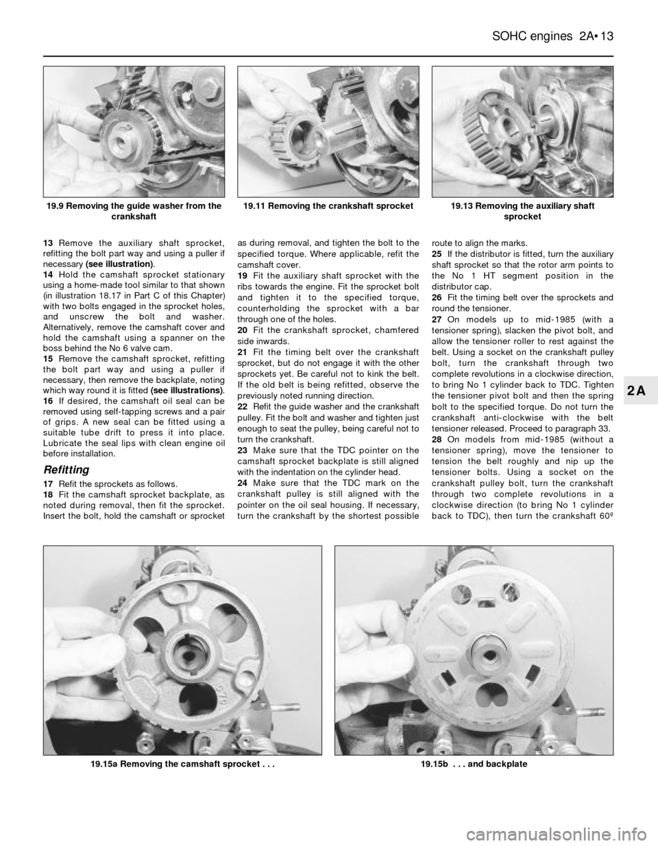
13Remove the auxiliary shaft sprocket,
refitting the bolt part way and using a puller if
necessary (see illustration).
14Hold the camshaft sprocket stationary
using a home-made tool similar to that shown
(in illustration 18.17 in Part C of this Chapter)
with two bolts engaged in the sprocket holes,
and unscrew the bolt and washer.
Alternatively, remove the camshaft cover and
hold the camshaft using a spanner on the
boss behind the No 6 valve cam.
15Remove the camshaft sprocket, refitting
the bolt part way and using a puller if
necessary, then remove the backplate, noting
which way round it is fitted (see illustrations).
16If desired, the camshaft oil seal can be
removed using self-tapping screws and a pair
of grips. A new seal can be fitted using a
suitable tube drift to press it into place.
Lubricate the seal lips with clean engine oil
before installation.
Refitting
17Refit the sprockets as follows.
18Fit the camshaft sprocket backplate, as
noted during removal, then fit the sprocket.
Insert the bolt, hold the camshaft or sprocketas during removal, and tighten the bolt to the
specified torque. Where applicable, refit the
camshaft cover.
19Fit the auxiliary shaft sprocket with the
ribs towards the engine. Fit the sprocket bolt
and tighten it to the specified torque,
counterholding the sprocket with a bar
through one of the holes.
20Fit the crankshaft sprocket, chamfered
side inwards.
21Fit the timing belt over the crankshaft
sprocket, but do not engage it with the other
sprockets yet. Be careful not to kink the belt.
If the old belt is being refitted, observe the
previously noted running direction.
22Refit the guide washer and the crankshaft
pulley. Fit the bolt and washer and tighten just
enough to seat the pulley, being careful not to
turn the crankshaft.
23Make sure that the TDC pointer on the
camshaft sprocket backplate is still aligned
with the indentation on the cylinder head.
24Make sure that the TDC mark on the
crankshaft pulley is still aligned with the
pointer on the oil seal housing. If necessary,
turn the crankshaft by the shortest possibleroute to align the marks.
25If the distributor is fitted, turn the auxiliary
shaft sprocket so that the rotor arm points to
the No 1 HT segment position in the
distributor cap.
26Fit the timing belt over the sprockets and
round the tensioner.
27On models up to mid-1985 (with a
tensioner spring), slacken the pivot bolt, and
allow the tensioner roller to rest against the
belt. Using a socket on the crankshaft pulley
bolt, turn the crankshaft through two
complete revolutions in a clockwise direction,
to bring No 1 cylinder back to TDC. Tighten
the tensioner pivot bolt and then the spring
bolt to the specified torque. Do not turn the
crankshaft anti-clockwise with the belt
tensioner released. Proceed to paragraph 33.
28On models from mid-1985 (without a
tensioner spring), move the tensioner to
tension the belt roughly and nip up the
tensioner bolts. Using a socket on the
crankshaft pulley bolt, turn the crankshaft
through two complete revolutions in a
clockwise direction (to bring No 1 cylinder
back to TDC), then turn the crankshaft 60¼
SOHC engines 2A¥13
2A
19.13 Removing the auxiliary shaft
sprocket
19.15b . . . and backplate19.15a Removing the camshaft sprocket . . .
19.11 Removing the crankshaft sprocket19.9 Removing the guide washer from the
crankshaft