FORD SUPER DUTY 2005 1.G Diesel Supplement Manual
Manufacturer: FORD, Model Year: 2005, Model line: SUPER DUTY, Model: FORD SUPER DUTY 2005 1.GPages: 72, PDF Size: 0.52 MB
Page 11 of 72
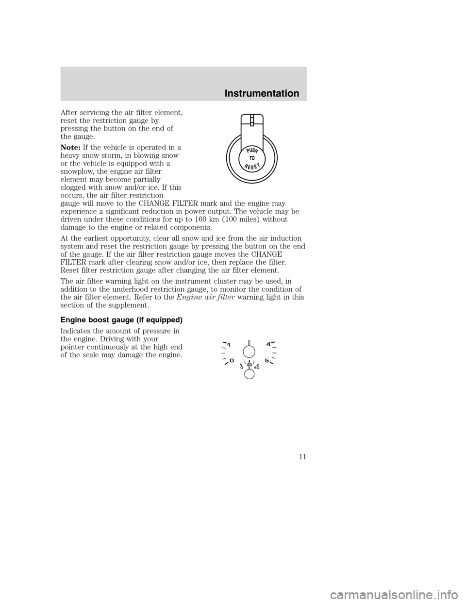
After servicing the air filter element,
reset the restriction gauge by
pressing the button on the end of
the gauge.
Note:If the vehicle is operated in a
heavy snow storm, in blowing snow
or the vehicle is equipped with a
snowplow, the engine air filter
element may become partially
clogged with snow and/or ice. If this
occurs, the air filter restriction
gauge will move to the CHANGE FILTER mark and the engine may
experience a significant reduction in power output. The vehicle may be
driven under these conditions for up to 160 km (100 miles) without
damage to the engine or related components.
At the earliest opportunity, clear all snow and ice from the air induction
system and reset the restriction gauge by pressing the button on the end
of the gauge. If the air filter restriction gauge moves the CHANGE
FILTER mark after clearing snow and/or ice, then replace the filter.
Reset filter restriction gauge after changing the air filter element.
The air filter warning light on the instrument cluster may be used, in
addition to the underhood restriction gauge, to monitor the condition of
the air filter element. Refer to theEngine air filterwarning light in this
section of the supplement.
Engine boost gauge (if equipped)
Indicates the amount of pressure in
the engine. Driving with your
pointer continuously at the high end
of the scale may damage the engine.
Instrumentation
11
Page 12 of 72
STARTING THE ENGINE
Read all starting instructions carefully before you start your vehicle.
For temperatures below 32°F(0°C), the use of the correct grade engine
oil is essential for proper operation.
If your vehicle is equipped with a manual transmission,make sure
the parking brake is set fully before you turn the key. Depress the clutch
pedal and place the gearshift in the neutral position. The clutch must be
fully depressed in order to operate the starter. Do not press the
accelerator during starting.
If your vehicle is equipped with an automatic transmission,ensure
the gearshift lever is in P (Park) and the parking brake is set before you
turn the key. Do not press the accelerator during starting.
Cold weather starting
When operating in cold weather, use a minimum of 45 Cetane Diesel fuel
or use Cetane Index improvers from a reputable manufacturer.
Do not crank the engine for more than 30 seconds as starter damage
may occur. If the engine fails to start, turn the key to 3 (OFF) and wait
30 seconds before trying again.
Do not use starting fluid, such as ether, in the air intake system
(see air cleaner decal). Such fluid could cause immediate
explosive damage to the engine and possible personal injury.
Note:Do not add gasoline, gasohol or alcohol to diesel fuel. This
practice creates a serious fire hazard and causes engine performance
problems.
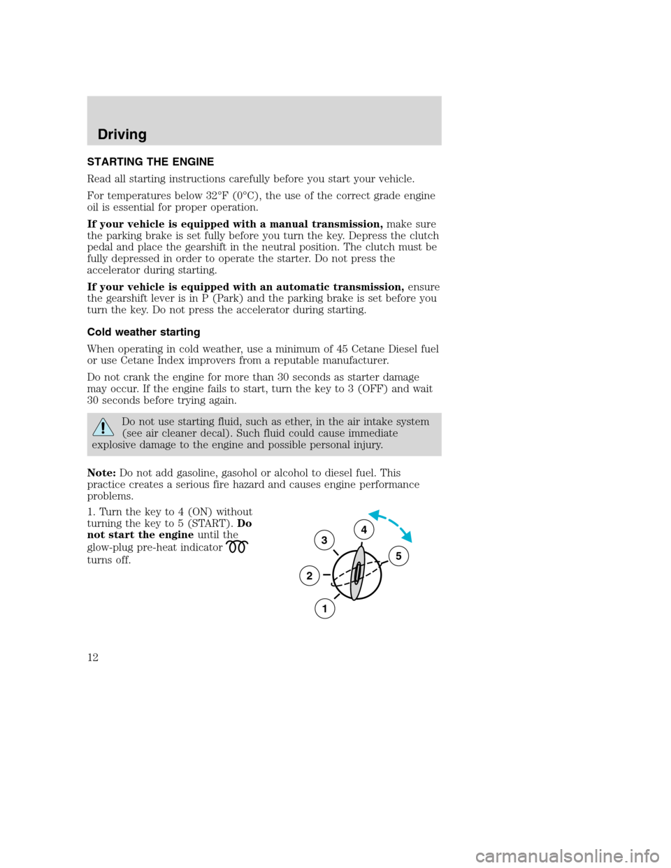
1. Turn the key to 4 (ON) without
turning the key to 5 (START).Do
not start the engineuntil the
glow-plug pre-heat indicator
turns off.
3
2
1
5
4
Driving
Driving
12
Page 13 of 72
2. When the glow plug pre-heat
indicator turns off, turn the key to 5
(START), then release the key as
soon as the engine starts. The glow
plugs will continue to be activated for two minutes after the glow plug
pre-heat indicator
has turned off. If the engine is not started
before the glow plug activation time ends, the glow plugs will need to be
reset by turning the key to 3 (OFF).
3. After the engine starts, allow it to idle for about 15 seconds. Do not
increase engine speed until the oil pressure gauge indicates normal
pressure.
STOPPING THE ENGINE
Turn the ignition to 3 (OFF). To prolong engine life (after extended high
speed or maximum GVW operation), it is recommended that a hot engine
be allowed to operate at low idle for about 7–10 minutes which would
allow sufficient time for the turbocharged engine to cool down.
COLD WEATHER OPERATION
Changing to a lighter grade engine oil also makes starting easier under
these conditions. Refer toEngine oil specificationsin theMaintenance
and Specificationssection of this supplement.
At temperatures below 20°F(–7°C), Number 2–D diesel fuel may thicken
enough to clog the fuel filter. Your vehicle is equipped with either an
FCM (E-Series) or an HFCM (F-Super Duty and Excursion) which acts
as a fuel filter/heater/water separator to keep the wax melted which will
help prevent fuel filter clogging. However, if the engine starts but stalls
after a short time and will not restart, the fuel filter(s) may be clogged.
For best results in cold weather, use Number 1–D diesel fuel or
“winterized”Number 2–D diesel fuel which has an additive to minimize
wax formation.
Your vehicle is also equipped with a bypass relief valve, located on the
fuel control module, which provides fuel flow to the engine if the fuel
pickup should become plugged by ice or wax. To allow this bypass valve
to function and avoid engine fuel starvation, it is recommended that,
during cold weather operation 32°F(0°C) or below, the fuel level in your
tank should not be allowed to drop below
1⁄4full. This will help prevent
air from entering the fuel system and stalling the engine.
In cold weather below 32°F (0°C) your diesel engine will slowly increase
to a higher idle speed if left idling in P (Park). As the engine warms-up,
Driving
13
Page 14 of 72
the engine sound level will decrease due to the activation of
PCM-controlled sound reduction features.
If your vehicle is operated in a heavy snow storm or blowing snow
conditions, the engine air induction may become partially clogged with
snow and/or ice. If this occurs, the engine may experience a significant
reduction in power output. At the earliest opportunity, clear all the snow
and/or ice away from the air induction inlet.
Operation in snow
Vehicle operation in heavy snowfall or in dry loose snow that may swirl
around the front of the vehicle may feed excessive amounts of snow into
the air intake system. This could plug the air cleaner with snow and
cause the engine to stall and/or lose power.
Refer toAir filter restriction gaugeandEngine air filterin the
Instrumentationsection of this supplement for more information.
Operation in standing water
Ingestion of water into the diesel engine can result in immediate and
severe damage to the engine. If driving through water, slow down to
avoid splashing water into the intake. If the engine stalls, and ingestion
of water into the engine is suspected, do not try to restart the engine.
Consult your dealer for service immediately.
Engine block heater (if equipped)
Refer to theDrivingchapter in theOwner’s Guide.
DUAL FUEL TANK SELECTOR CONTROL (IF EQUIPPED)
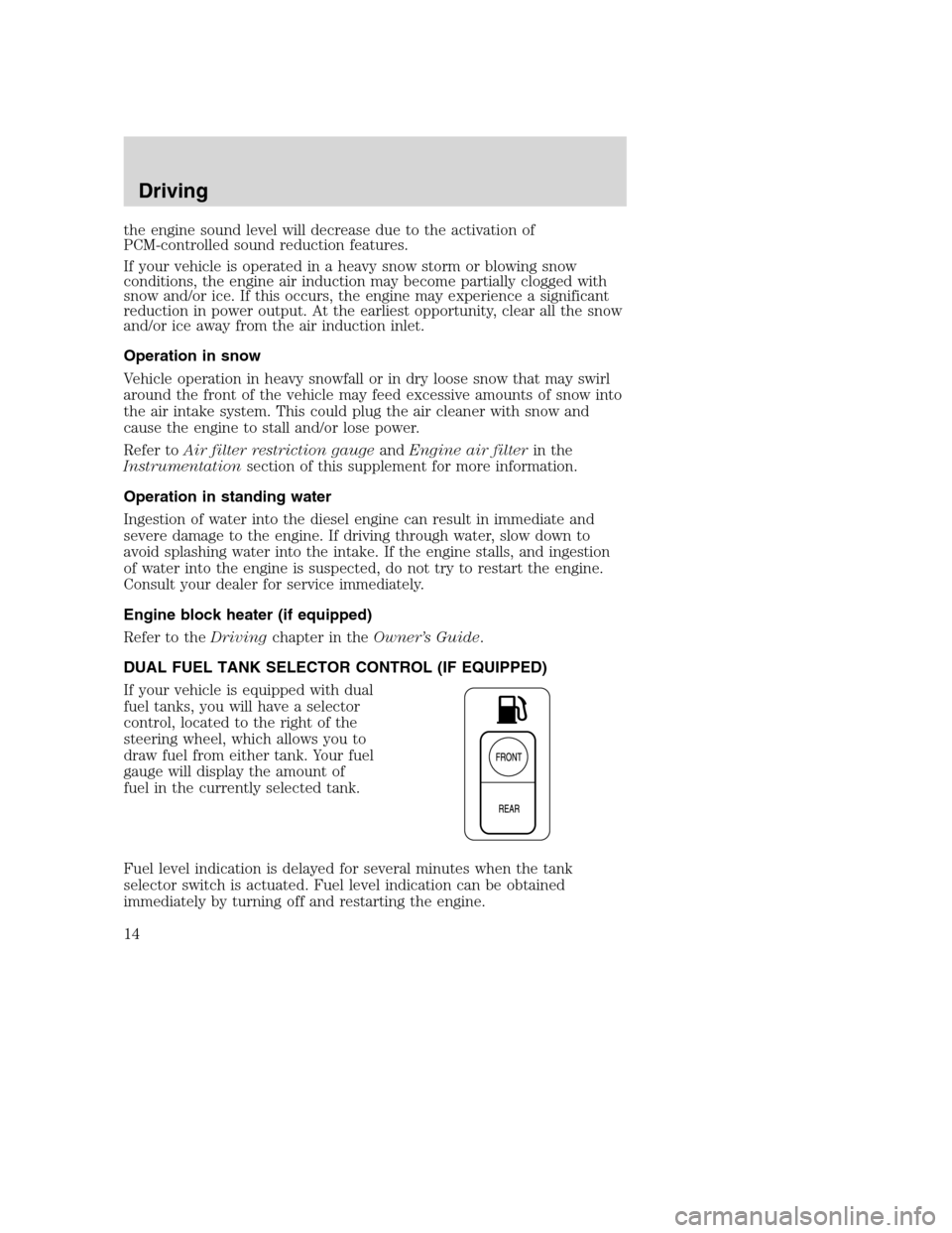
If your vehicle is equipped with dual
fuel tanks, you will have a selector
control, located to the right of the
steering wheel, which allows you to
draw fuel from either tank. Your fuel
gauge will display the amount of
fuel in the currently selected tank.
Fuel level indication is delayed for several minutes when the tank
selector switch is actuated. Fuel level indication can be obtained
immediately by turning off and restarting the engine.
Driving
14
Page 15 of 72
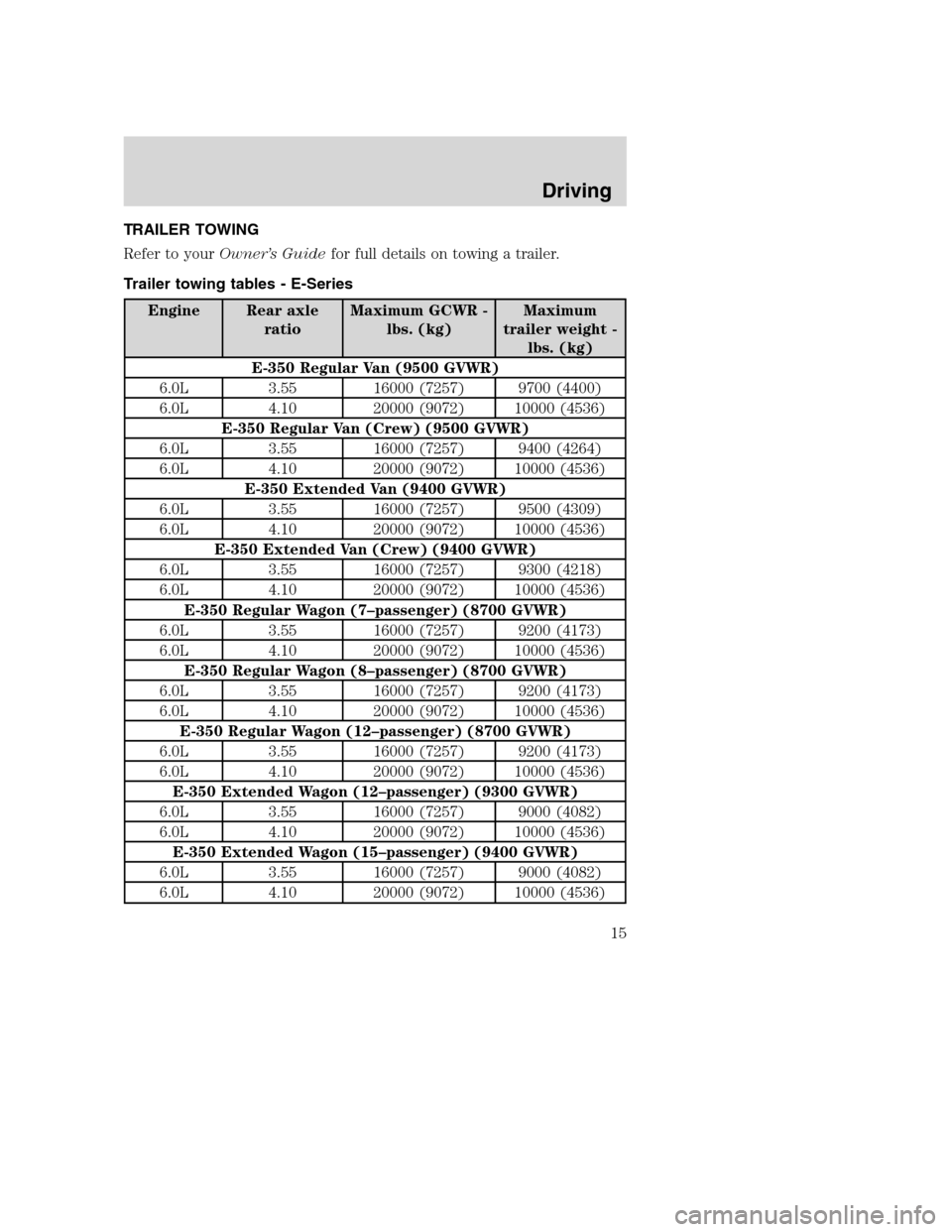
TRAILER TOWING
Refer to yourOwner’s Guidefor full details on towing a trailer.
Trailer towing tables - E-Series
Engine Rear axle
ratioMaximum GCWR -
lbs. (kg)Maximum
trailer weight -
lbs. (kg)
E-350 Regular Van (9500 GVWR)
6.0L 3.55 16000 (7257) 9700 (4400)
6.0L 4.10 20000 (9072) 10000 (4536)
E-350 Regular Van (Crew) (9500 GVWR)
6.0L 3.55 16000 (7257) 9400 (4264)
6.0L 4.10 20000 (9072) 10000 (4536)
E-350 Extended Van (9400 GVWR)
6.0L 3.55 16000 (7257) 9500 (4309)
6.0L 4.10 20000 (9072) 10000 (4536)
E-350 Extended Van (Crew) (9400 GVWR)
6.0L 3.55 16000 (7257) 9300 (4218)
6.0L 4.10 20000 (9072) 10000 (4536)
E-350 Regular Wagon (7–passenger) (8700 GVWR)
6.0L 3.55 16000 (7257) 9200 (4173)
6.0L 4.10 20000 (9072) 10000 (4536)
E-350 Regular Wagon (8–passenger) (8700 GVWR)
6.0L 3.55 16000 (7257) 9200 (4173)
6.0L 4.10 20000 (9072) 10000 (4536)
E-350 Regular Wagon (12–passenger) (8700 GVWR)
6.0L 3.55 16000 (7257) 9200 (4173)
6.0L 4.10 20000 (9072) 10000 (4536)
E-350 Extended Wagon (12–passenger) (9300 GVWR)
6.0L 3.55 16000 (7257) 9000 (4082)
6.0L 4.10 20000 (9072) 10000 (4536)
E-350 Extended Wagon (15–passenger) (9400 GVWR)
6.0L 3.55 16000 (7257) 9000 (4082)
6.0L 4.10 20000 (9072) 10000 (4536)
Driving
15
Page 16 of 72
Engine Rear axle
ratioMaximum GCWR -
lbs. (kg)Maximum
trailer weight -
lbs. (kg)
E-350 Cutaway 138”wheelbase, single rear wheel) (9600
GVWR)
6.0L 4.10 20000 (9072) 10000 (4536)
E-350 Cutaway 138”wheelbase, dual rear wheel) (10700 GVWR)
6.0L 4.10 20000 (9072) 10000 (4536)
E-350 Cutaway 158”wheelbase, dual rear wheel) (11500 GVWR)
6.0L 4.10 20000 (9072) 10000 (4536)
E-350 Cutaway 176”wheelbase, dual rear wheel) (11500 GVWR)
6.0L 4.10 20000 (9072) 10000 (4536)
E-450 Cutaway 158”wheelbase) (14050 GVWR)
6.0L 4.10 20000 (9072) 10000 (4536)
E-350 Cutaway 176”wheelbase) (14050 GVWR)
6.0L 4.10 20000 (9072) 10000 (4536)
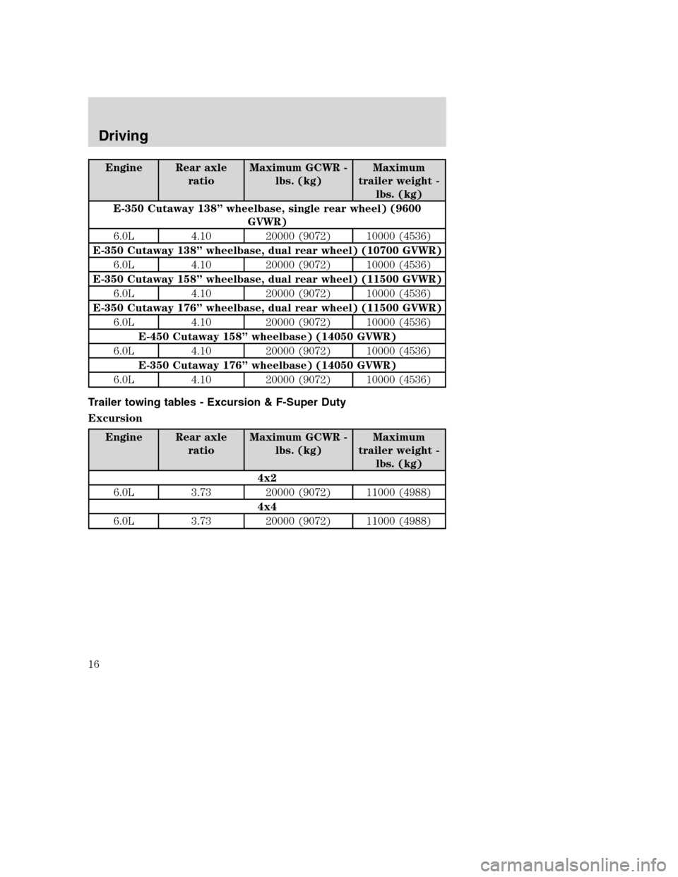
Trailer towing tables - Excursion & F-Super Duty
Excursion
Engine Rear axle
ratioMaximum GCWR -
lbs. (kg)Maximum
trailer weight -
lbs. (kg)
4x2
6.0L 3.73 20000 (9072) 11000 (4988)
4x4
6.0L 3.73 20000 (9072) 11000 (4988)
Driving
16
Page 17 of 72
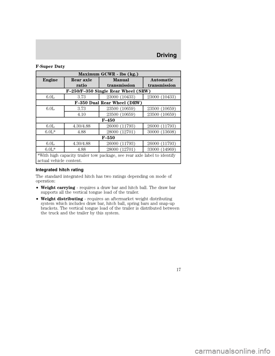
F-Super Duty
Maximum GCWR - lbs (kg.)
Engine Rear axle
ratioManual
transmissionAutomatic
transmission
F–250/F–350 Single Rear Wheel (SRW)
6.0L 3.73 23000 (10433) 23000 (10433)
F–350 Dual Rear Wheel (DRW)
6.0L 3.73 23500 (10659) 23500 (10659)
4.10 23500 (10659) 23500 (10659)
F–450
6.0L 4.30/4.88 26000 (11793) 26000 (11793)
6.0L* 4.88 28000 (12701) 30000 (13608)
F–550
6.0L 4.30/4.88 26000 (11793) 26000 (11793)
6.0L* 4.88 28000 (12701) 33000 (14969)
*With high capacity trailer tow package, see rear axle label to identify
actual vehicle content.
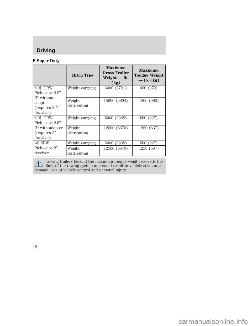
Integrated hitch rating
The standard integrated hitch has two ratings depending on mode of
operation:
•Weight carrying- requires a draw bar and hitch ball. The draw bar
supports all the vertical tongue load of the trailer.
•Weight distributing- requires an aftermarket weight distributing
system which includes draw bar, hitch ball, spring bars and snap-up
brackets. The vertical tongue load of the trailer is distributed between
the truck and the trailer by this system.
Driving
17
Page 18 of 72
F-Super Duty
Hitch TypeMaximum
Gross Trailer
Weight—lb.
(kg)Maximum
Tongue Weight
—lb. (kg)
6.0L DRW
Pick—ups 2.5”
ID without
adapter
(requires 2.5”
drawbar)Weight carrying 6000 (2721) 600 (272)
Weight
distributing15000 (6804) 1500 (680)
6.0L DRW
Pick—ups 2.5”
ID with adapter
(requires 2”
drawbar)Weight carrying 5000 (2268) 500 (227)
Weight
distributing12500 (5670) 1250 (567)
All SRW
Pick—ups 2”
receiverWeight carrying 5000 (2268) 500 (227)
Weight
distributing12500 (5670) 1250 (567)
Towing trailers beyond the maximum tongue weight exceeds the
limit of the towing system and could result in vehicle structural
damage, loss of vehicle control and personal injury.
Driving
18
Page 19 of 72
JUMP STARTING YOUR VEHICLE (E-SERIES ONLY)
F-Super Duty and Excursion vehicles equipped with the 6.0L
diesel engine can be jump started using the same procedure as a
gasoline engine; refer to yourOwner’s guidefor the jump starting
procedure.
The gases around the battery can explode if exposed to flames,
sparks, or lit cigarettes. An explosion could result in injury or
vehicle damage.
Batteries contain sulfuric acid which can burn skin, eyes and
clothing, if contacted.
Do not attempt to push-start your vehicle. Automatic
transmissions do not have push-start capability; doing so may
damage the catalytic converter.
Preparing your vehicle
When the batteries are disconnected or new batteries are installed, the
transmission must relearn its shift strategy. As a result, the transmission
may have firm and/or soft shifts. This operation is considered normal and
will not affect function or durability of the transmission. Over time, the
adaptive learning process will fully update transmission operation
1.Use only a 12–volt supply to start your vehicle.
2. Do not disconnect the batteries of the disabled vehicle as this could
damage the vehicle’s electrical system.
3. Park the booster vehicle close to the passenger side of the disabled
vehicle making sure the two vehiclesdo nottouch. Set the parking
brake on both vehicles.
Note:This vehicle has two frame-mounted batteries located on the
passenger side frame rail, behind the front passenger door. A battery
positive (+) jumper stud is located on the frame rail behind the rear
most battery box.
Roadside emergencies
Roadside emergencies
19
Page 20 of 72
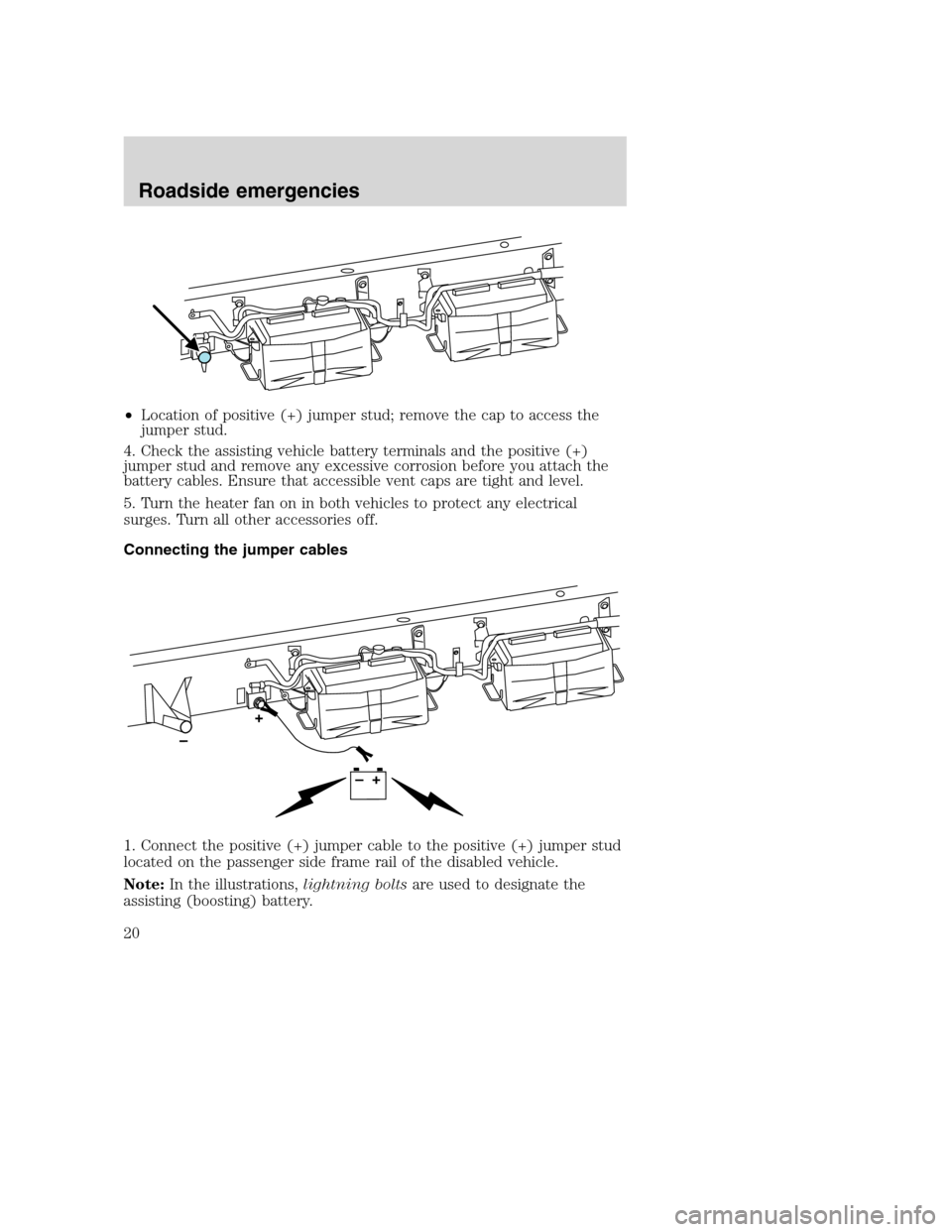
•Location of positive (+) jumper stud; remove the cap to access the
jumper stud.
4. Check the assisting vehicle battery terminals and the positive (+)
jumper stud and remove any excessive corrosion before you attach the
battery cables. Ensure that accessible vent caps are tight and level.
5. Turn the heater fan on in both vehicles to protect any electrical
surges. Turn all other accessories off.
Connecting the jumper cables
1. Connect the positive (+) jumper cable to the positive (+) jumper stud
located on the passenger side frame rail of the disabled vehicle.
Note:In the illustrations,lightning boltsare used to designate the
assisting (boosting) battery.
Roadside emergencies
20