FORD SUPER DUTY 2006 1.G Special Off-Road Package Supplement Manual
Manufacturer: FORD, Model Year: 2006, Model line: SUPER DUTY, Model: FORD SUPER DUTY 2006 1.GPages: 28, PDF Size: 0.22 MB
Page 11 of 28
9. Slowly wind the wire rope until no slack remains by using the winch
switch. Once the wire rope is under tension, stand clear and never step
over it.
10. Check the anchor point. Make sure all connections are secured and
free of debris before continuing with the winching procedure.
Never use the winch as a hoist. Never use the winch's wire rope
to tow another vehicle.
11. Check the wire rope. It should be neatly wound around the drum.
Improper winding can cause damage to the wire rope.
12. Lay something over the wire rope to absorb energy should the rope
snap. Tree limbs, heavy jackets, chain and the like may be used for this
purpose.
Note:Always avoid continuous side pulls which can pile up wire rope at
one end of the drum. This pile can damage the wire rope or the winch.
13. Make sure everyone in the immediate area is aware of the winching
operation. Tell them where they shouldn't stand; never behind or in front
of the vehicle and never near the wire rope.
14. With the vehicle's engine on and light tension on the wire rope, begin
winching slowly and steadily. Be sure the wire rope is winding evenly
and tightly around the drum. For assistance, the winched vehicle can be
slowly driven while being pulled by the winch.
Note:Avoid overheating of the winch motor. For extended winching,
stop at reasonable intervals to allow the winch motor to cool down.
What to look for under load
The wire rope must always spool onto the drum as indicated by the
drum rotation decal on the winch. As you power in, make sure the rope
winds evenly and tightly on the drum. This prevents the outer wrap from
drawing into the inner wraps, binding and damaging the rope. Avoid
shock loads by using the control switch intermittently to take up wire
rope slack. During side pulls, the wire rope tends to stack up at one end
of the drum. This stack can become large enough to cause serious
damage to the winch. Line up pulls as straight as possible and stop
winching if the wire rope comes close to the tie rods or mounting plate.
Note:To fix an uneven stack, spool out that section of the rope and
reposition it to the opposite end of the drum; this will free up space for
continued winching.
15. For vehicle recovery, continue pulling until the vehicle is on stable
ground. If the vehicle is able to be driven, the winching operation is
complete.
Driver Controls
11
Page 12 of 28
16. Once recovery of the vehicle is complete, be sure to secure the
vehicle's brakes and put the transmission in P (Park) (automatic
transmission) or 1 (First) (manual transmission). Release tension in the
wire rope.
17. Disconnect the wire rope from the anchor.
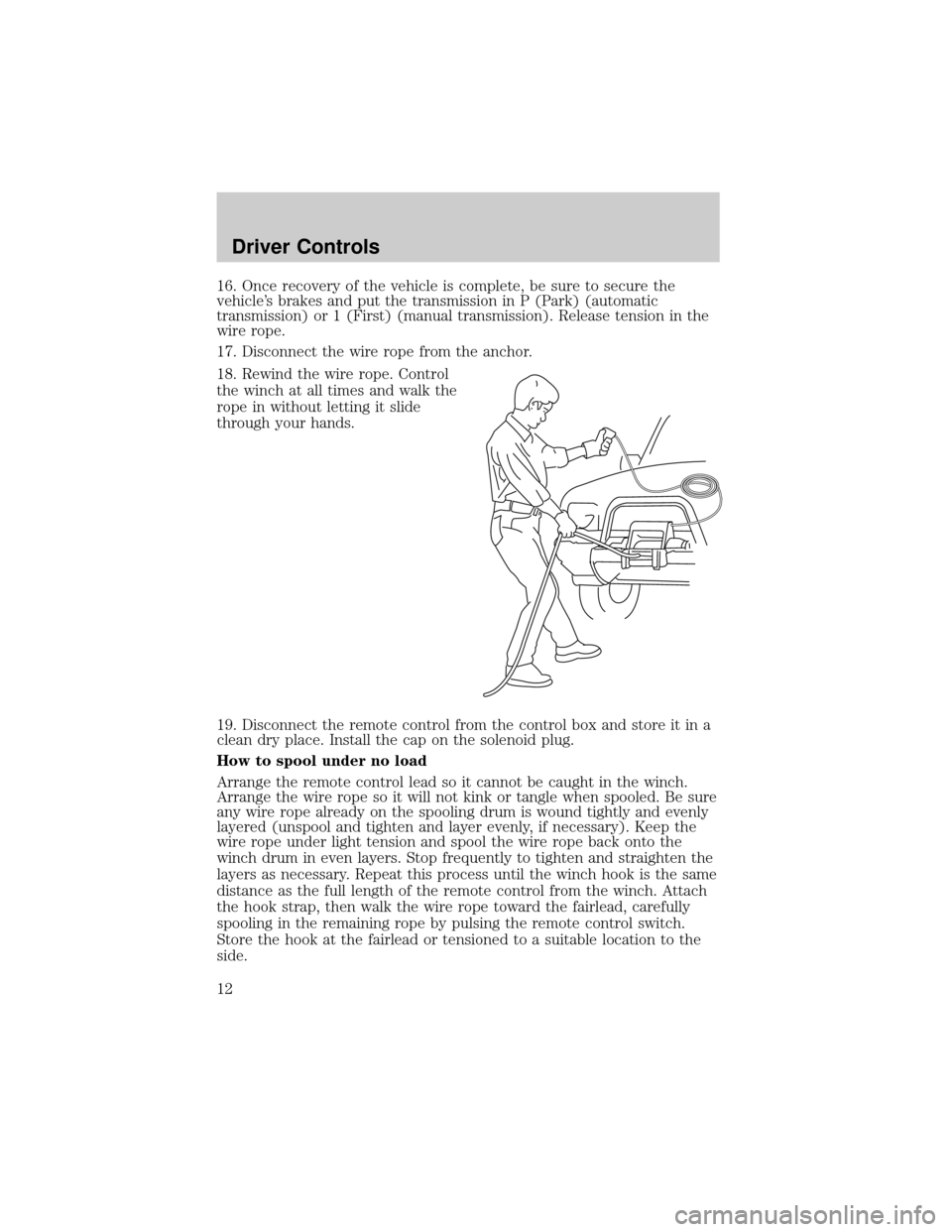
18. Rewind the wire rope. Control
the winch at all times and walk the
rope in without letting it slide
through your hands.
19. Disconnect the remote control from the control box and store it in a
clean dry place. Install the cap on the solenoid plug.
How to spool under no load
Arrange the remote control lead so it cannot be caught in the winch.
Arrange the wire rope so it will not kink or tangle when spooled. Be sure
any wire rope already on the spooling drum is wound tightly and evenly
layered (unspool and tighten and layer evenly, if necessary). Keep the
wire rope under light tension and spool the wire rope back onto the
winch drum in even layers. Stop frequently to tighten and straighten the
layers as necessary. Repeat this process until the winch hook is the same
distance as the full length of the remote control from the winch. Attach
the hook strap, then walk the wire rope toward the fairlead, carefully
spooling in the remaining rope by pulsing the remote control switch.
Store the hook at the fairlead or tensioned to a suitable location to the
side.
Driver Controls
12
Page 13 of 28
If you do not have the hook strap, use a length of cord or something
similar.
To help prevent serious injury,neverput your fingers inside the
hook area as you are powering in.
Rigging techniques
Various winching situations will require unique winching techniques.
These could range from too little distance to achieve maximum pull
using straight line rigging, simply increasing pulling power or maintaining
a straight-line pulling situation.
How to change the pulling direction
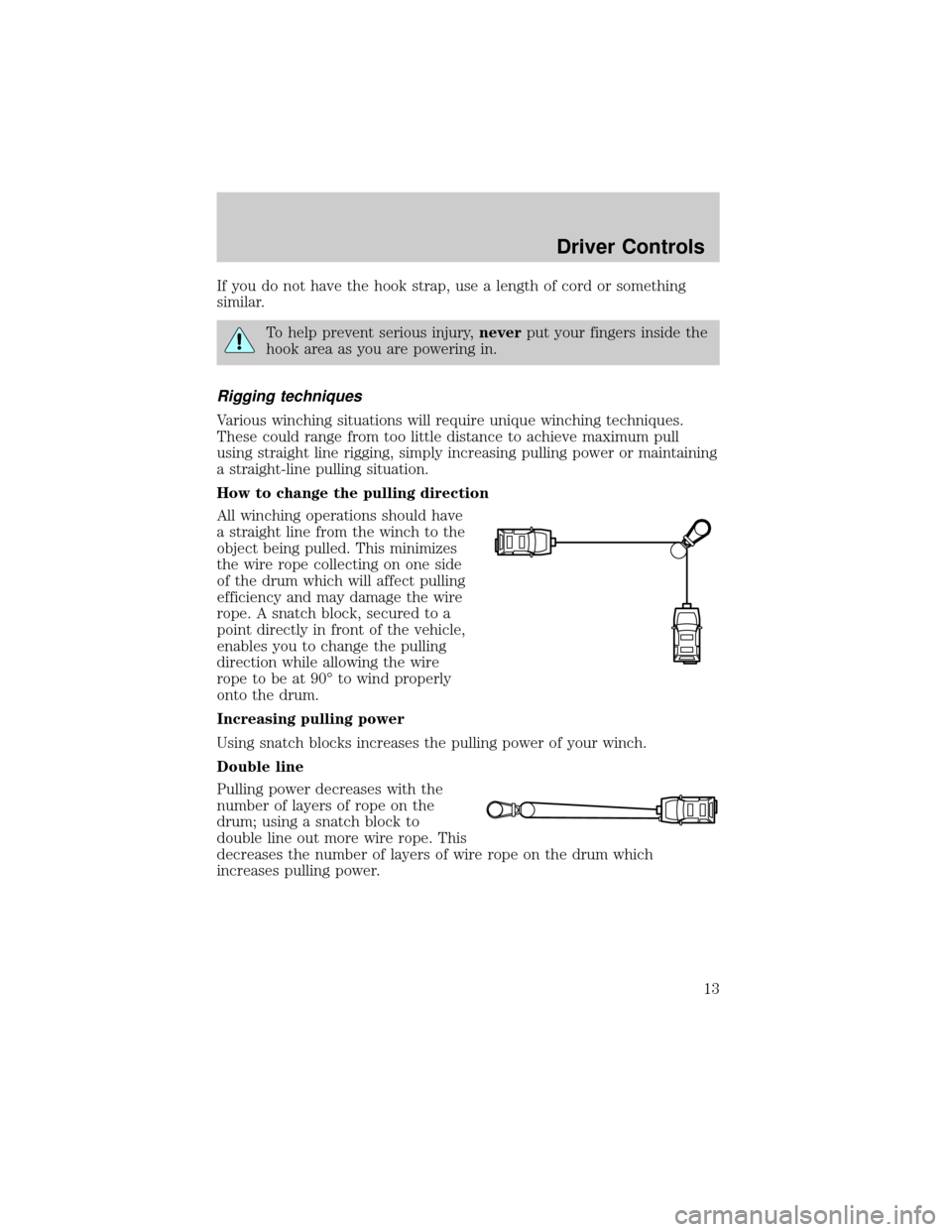
All winching operations should have
a straight line from the winch to the
object being pulled. This minimizes
the wire rope collecting on one side
of the drum which will affect pulling
efficiency and may damage the wire
rope. A snatch block, secured to a
point directly in front of the vehicle,
enables you to change the pulling
direction while allowing the wire
rope to be at 90É to wind properly
onto the drum.
Increasing pulling power
Using snatch blocks increases the pulling power of your winch.
Double line
Pulling power decreases with the
number of layers of rope on the
drum; using a snatch block to
double line out more wire rope. This
decreases the number of layers of wire rope on the drum which
increases pulling power.
Driver Controls
13
Page 14 of 28
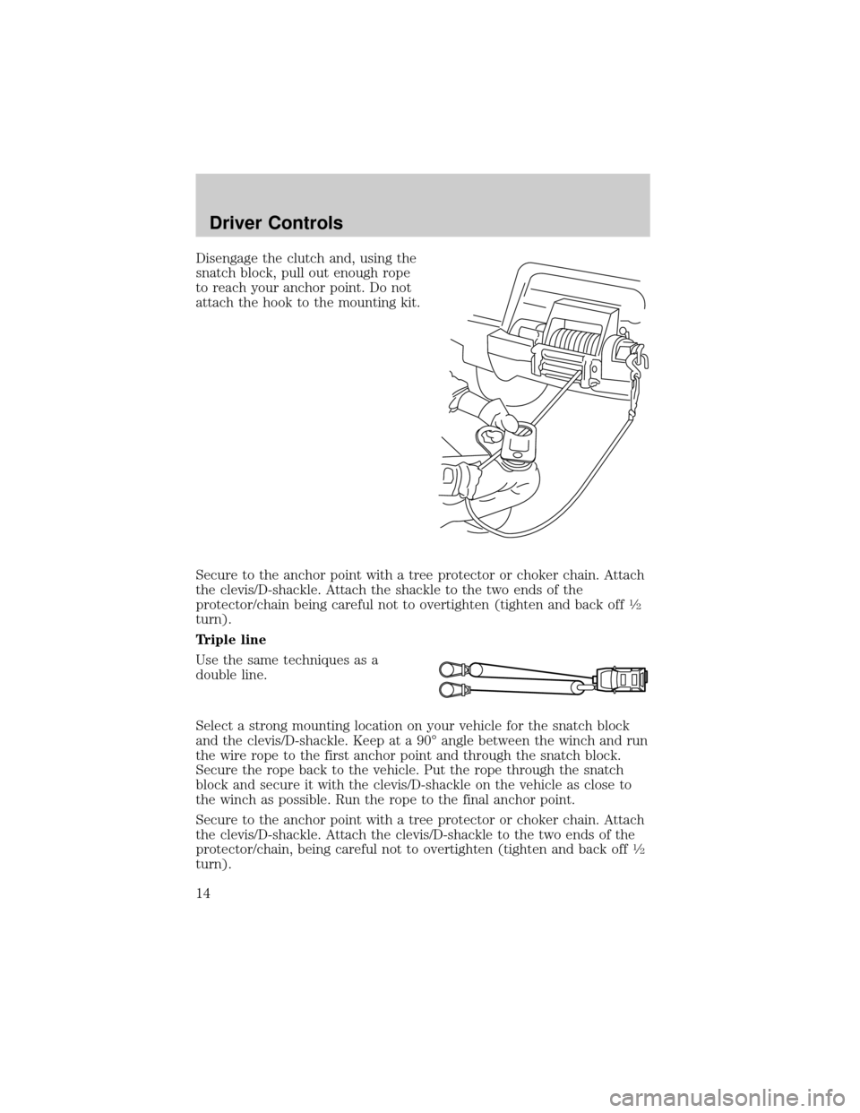
Disengage the clutch and, using the
snatch block, pull out enough rope
to reach your anchor point. Do not
attach the hook to the mounting kit.
Secure to the anchor point with a tree protector or choker chain. Attach
the clevis/D-shackle. Attach the shackle to the two ends of the
protector/chain being careful not to overtighten (tighten and back off
1¤2
turn).
Triple line
Use the same techniques as a
double line.
Select a strong mounting location on your vehicle for the snatch block
and the clevis/D-shackle. Keep at a 90É angle between the winch and run
the wire rope to the first anchor point and through the snatch block.
Secure the rope back to the vehicle. Put the rope through the snatch
block and secure it with the clevis/D-shackle on the vehicle as close to
the winch as possible. Run the rope to the final anchor point.
Secure to the anchor point with a tree protector or choker chain. Attach
the clevis/D-shackle. Attach the clevis/D-shackle to the two ends of the
protector/chain, being careful not to overtighten (tighten and back off
1¤2
turn).
Driver Controls
14
Page 15 of 28

Secure the winch hook. While keeping the line near the ground, insert
the winch hook through the clevis/D-shackle. Check the anchor. Make
sure all connections are secured and free of debris before continuing
with the winching procedure.
Maintenance
²Inspect the wire rope before and after each winching operation. If the
wire rope has become kinked or frayed, it needs to be replaced. Be
sure to also inspect the winch hook and hook pin for signs of wear or
damage. Replace as necessary.
²Keep winch, wire rope and switch control free from contaminants. Use
a clean rag or towel to remove any dirt and debris. If necessary,
unwind the winch completely (leaving a minimum of five wraps of
rope on the drum) and wipe it clean before rewinding it. Using a light
oil on the rope and winch hook can keep rust and corrosion from
forming.
²Operating the winch for an extended period of time places an
additional load on your vehicle battery. Be sure to check and maintain
your battery and battery cables according to manufacturer guidelines.
Also, inspect the switch control and all electrical connections to be
certain they are clean and tight fitting.
²Inspect the remote control, if so equipped, for damage. Be sure to cap
the remote socket to prevent dirt and debris from entering the
connections. Store the remote control in a dry, protected area.
²No lubrication is required for the life of the winch.
Driver Controls
15
Page 16 of 28
24±VOLT CONVERTER (IF EQUIPPED)
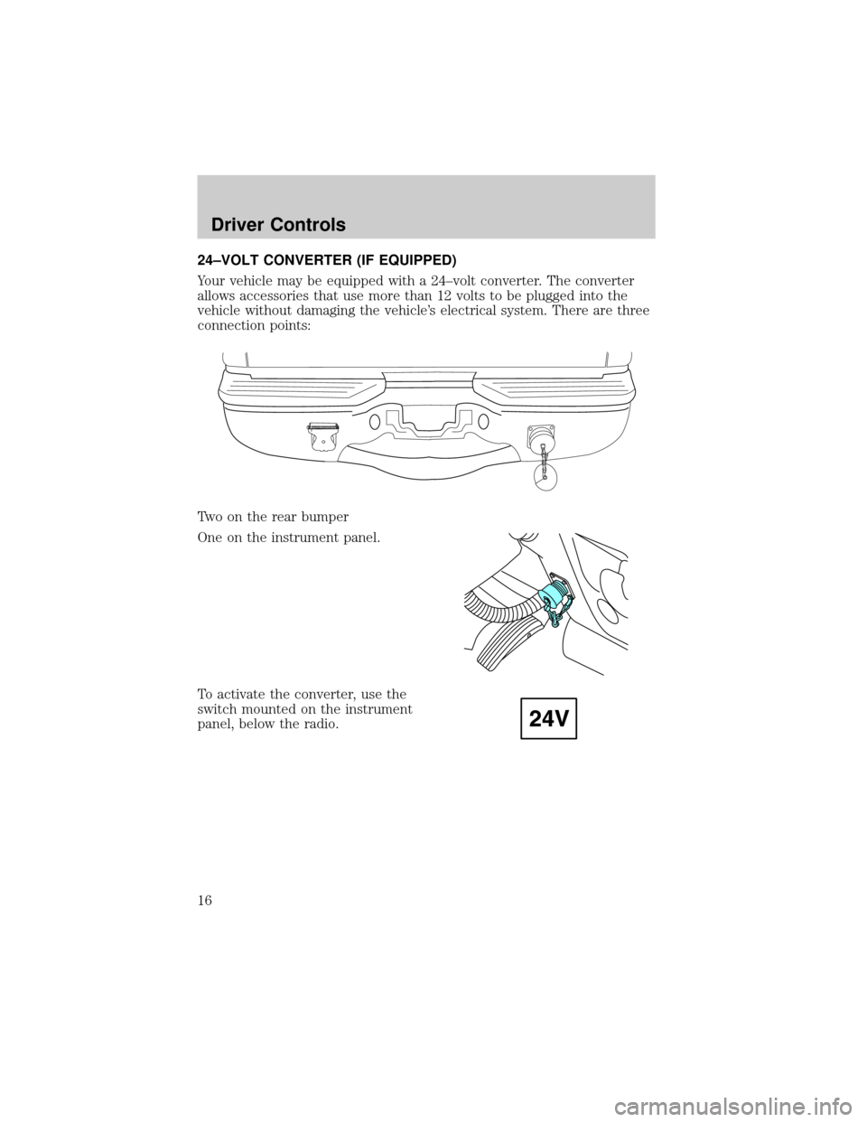
Your vehicle may be equipped with a 24±volt converter. The converter
allows accessories that use more than 12 volts to be plugged into the
vehicle without damaging the vehicle's electrical system. There are three
connection points:
Two on the rear bumper
One on the instrument panel.
To activate the converter, use the
switch mounted on the instrument
panel, below the radio.
Driver Controls
16
Page 17 of 28
AIRBAGS
Refer to the label on the front of the sun visors regarding airbag and
seatbelt usage.
This vehicle is not equipped with airbags. Always wear your
seatbelt.
Safety Restraints
17
Page 18 of 28
ANTI-LOCK BRAKE SYSTEM (ABS) DEACTIVATION IN 4WD
(IF EQUIPPED)
Refer to the label on the back of the sun visor mirror regarding Anti-lock
Brake System (ABS) operation.
Your vehicle may be equipped with a feature that deactivates the
Anti-lock Brake System (ABS) when 4WD Low is engaged. The ABS
indicator (
ABS) illuminates, to indicate that ABS is deactivated, and
stays on as long as 4WD Low is engaged.
When 4WD Low is disengaged, the ABS light turns off and the system is
active again.
SUSPENSION UPGRADE PACKAGE
Your vehicle is equipped with a special suspension package that will
enhance the vehicle's off-road performance. The vehicle will handle
differently, both on and off-road, from a factory-equipped passenger car
or truck.
Vehicles with a higher center of gravity such as utility and
four-wheel drive vehicles handle differently than vehicles with a
lower center of gravity. Utility and four-wheel drive vehicles are not
designed for cornering at speeds as high as passenger cars any more
than low-slung sports cars are designed to perform satisfactorily under
off-road conditions. Avoid sharp turns, excessive speed and abrupt
maneuvers in these vehicles. Failure to drive cautiously could result in
an increased risk of loss of vehicle control, vehicle rollover, personal
injury and death.
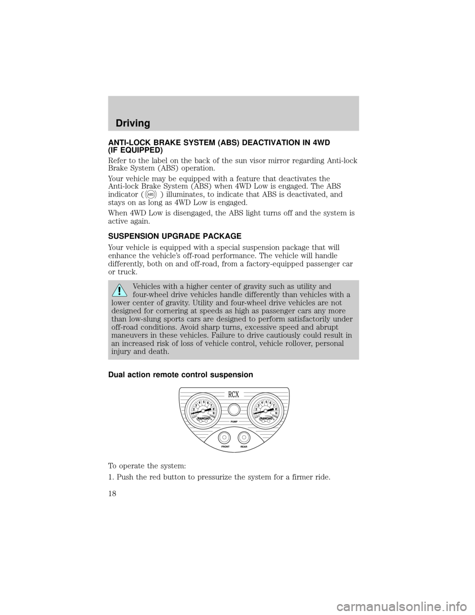
Dual action remote control suspension
To operate the system:
1. Push the red button to pressurize the system for a firmer ride.
Driving
18
Page 19 of 28
2. Push the black buttons on the bleed valves for a softer ride. Separate
bleed valves allow independent adjustment of front and rear shocks.
Note:Do not operate the compressor for more than 30 seconds at a
time. Allow the compressor to cool down for one minute between
operations.
Note:Stop compressor operation when the arrow on the gauge reaches
maximum. Continuing to supply pressure will not make the shocks any
firmer and damage to the system will occur.
The following table is an example of typical settings for the suspension.
Setting Front Rear
High-speed firm ride 8 6
Slow-speed soft ride 2 2
Towing 5 8
LOCKING REAR DIFFERENTIAL
General information
Your vehicle may be equipped with a locking rear differential; vehicles
equipped with this differential should be identified by a ªCautionº label
mounted on the instrument panel. Vehicle handling characteristcs will be
different than a conventional differential. Examples of this would be:
²When turning a corner, the sound of component disengagement and
re-engagement may be audible, and the transfer of driving torque from
both wheels to one wheel may be noticeable.
²When going from drive (acceleration) to coast (deceleration) in a
turn, a ªmetallicº sound may be heard as torque flow is reversed
(inside wheel engaged during acceleration; outside wheel engaged
during deceleration).
²When negotiating a turn (outside wheel disengaged), the inside wheel
under conditions of poor traction may receive excessive torque, which
could cause it to break traction momentarily until its speed is equal to
the outside wheel. This will result in re-engagement of the outside
wheel thus allowing both wheels to be driven. This condition is most
noticeable with lightly loaded axles.
Driving
19
Page 20 of 28
Use extreme caution when accelerating or decelerating on
slippery or unstable surfaces. Vehicles/axles equipped with
traction differentials are inherently more sensitive to side-slip than
vehicles equipped with conventional differentials. Stability can be
retained if side-slip occurs by decelerating (letting off the accelerator).
Do not apply the brake. To do so may result in loss of vehicle control.
The vehicle's braking capacity is reduced when a turn is made while
coasting downhill because the inside wheel is then disconnected from the
driveline. Operating in low gear will allow the engine to act as a retarder
and will improve braking capacity.
Inspection and lubrication
When servicing any driveline components on a vehicle equipped
with a locking rear differential, ensure that the engine is off and
all wheels are off the ground to prevent the vehicle from moving. Axles
equipped with a locking rear differential deliver power to both wheels,
even when only one wheel is on the ground. Failure to observe these
cautionary measures may cause the vehicle to move which can result
in property damage, personal injury, even death.
This differential is designed to operate in the lubricant recommended by
the vehicle/axle manufacturer; no special lubricant is needed. Refer to
theLubricant Specificationsin yourOwner's Guidefor the proper axle
lubricant. For very cold weather applications, use the lightest oil the axle
manufacturer will allow to overcome possible sluggish reengagement of
the driven clutch assemblies.
No adjustments or alterations should be made to the differential. Refer to
the vehicle/axle manufacturer's instructions for adjustments to other
components in the axle.
SAND INGESTION
When driving through sand, traction or brake capability may be limited.
Also, sand may enter your engine's air intake and severely damage your
engine or your vehicle may stall. Driving through sand where the
transmission vent tube or external breather kit is submerged may allow
sand into the transmission and cause internal transmission damage.
Driving
20