FORD SUPER DUTY 2006 1.G Special Off-Road Package Supplement Manual
Manufacturer: FORD, Model Year: 2006, Model line: SUPER DUTY, Model: FORD SUPER DUTY 2006 1.GPages: 28, PDF Size: 0.22 MB
Page 21 of 28

WHEELS
Your vehicle may be equipped with two-piece bolt-together beadlock
rims. Beadlock rims allow the tires to survive operating at lower air
pressure which provide greater traction due to the larger tire-to-ground
contact area during slow, off-road operation. Always reinflate the tires to
the tire manufacturer's recommendations when no longer in slow,
off-road driving conditions. The beadlock also acts as a safety device
ensuring that the tire does not unseat from the rim or rotate on the
wheel when tire pressure is reduced, while also preventing the entry of
foreign objects, debris or water into the tire's air chamber.
Note:The wheel/tire assemblies should be serviced only by trained
personnel who have read and understand the wheel
assembly/disassembly information contained within theWorkshop
Manual.
TIRES
Each tire is equipped with a Variable Function Insert (VFI) which is
mounted into the tire. The VFI insert and tire are then fitted around the
beadlock rim assembly, providing a higher level of tire protection due to
the dense rubber material in the tire assembly and maximum all-terrain
mobility.
SNOW CHAINS
Tire chains cannot be used on vehicles equipped with M/TR tires.
ON-BOARD AIR SYSTEM (IF EQUIPPED)
Your vehicle may be equipped with an on-board air system which has
been designed to provide compressed air for multiple uses, including the
addition of air to the vehicle's tires. The system uses a 25 ft. (7.6m)
length of air hose equipped with a clamp-on style air chuck. When not in
use, this hose is secured to the floor of the truck. A compressor,
mounted to the frame under the truck on the passenger side frame rail,
is included along with an air reservoir on the driver side. When the
compressor is on, the output pressure at the air tank is limited to 80 psi
(552 kPa).
Tires, Wheels and Loading
21
Page 22 of 28
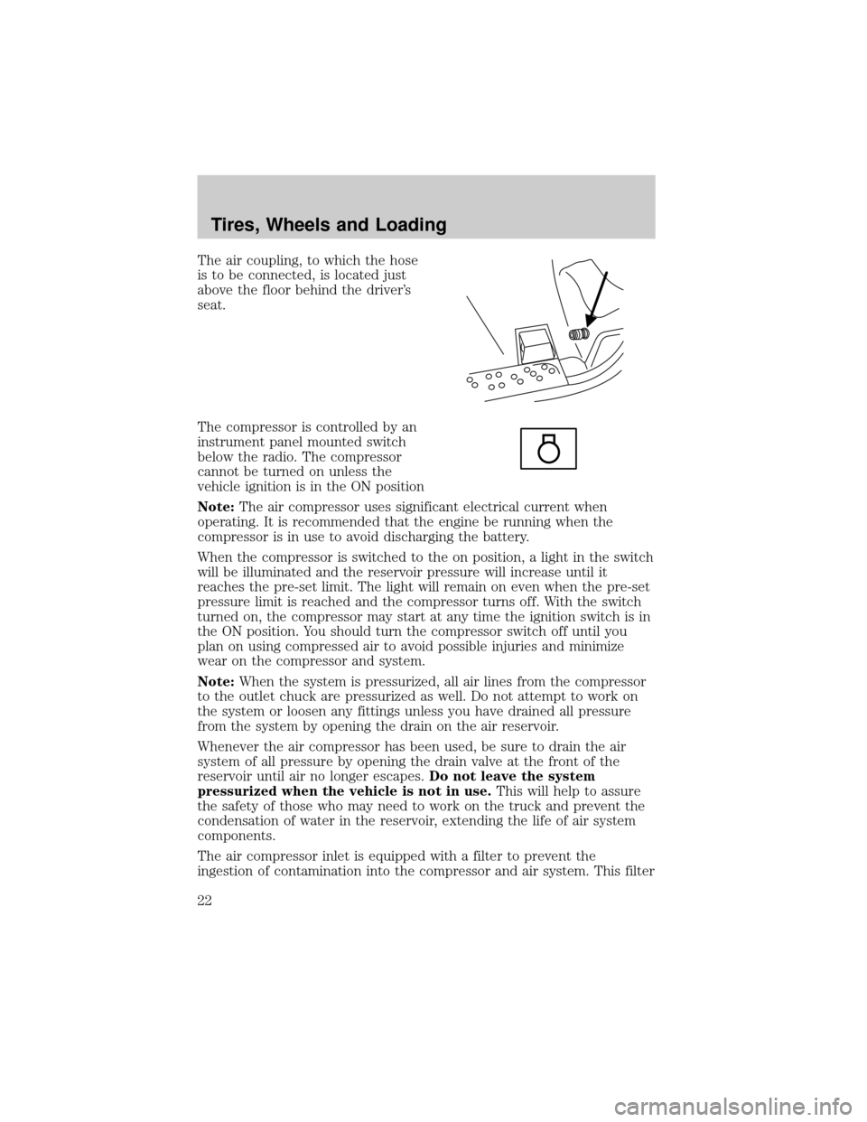
The air coupling, to which the hose
is to be connected, is located just
above the floor behind the driver's
seat.
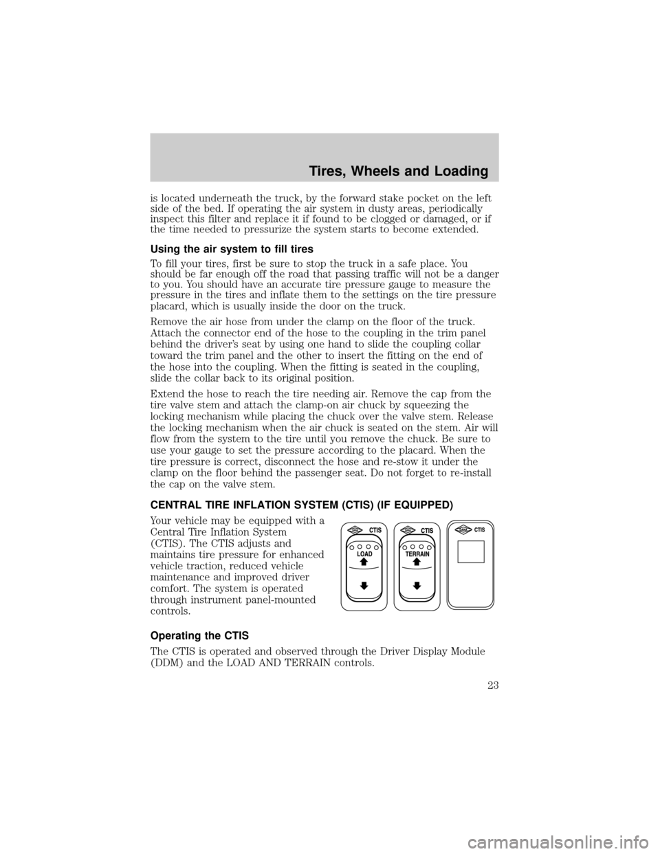
The compressor is controlled by an
instrument panel mounted switch
below the radio. The compressor
cannot be turned on unless the
vehicle ignition is in the ON position
Note:The air compressor uses significant electrical current when
operating. It is recommended that the engine be running when the
compressor is in use to avoid discharging the battery.
When the compressor is switched to the on position, a light in the switch
will be illuminated and the reservoir pressure will increase until it
reaches the pre-set limit. The light will remain on even when the pre-set
pressure limit is reached and the compressor turns off. With the switch
turned on, the compressor may start at any time the ignition switch is in
the ON position. You should turn the compressor switch off until you
plan on using compressed air to avoid possible injuries and minimize
wear on the compressor and system.
Note:When the system is pressurized, all air lines from the compressor
to the outlet chuck are pressurized as well. Do not attempt to work on
the system or loosen any fittings unless you have drained all pressure
from the system by opening the drain on the air reservoir.
Whenever the air compressor has been used, be sure to drain the air
system of all pressure by opening the drain valve at the front of the
reservoir until air no longer escapes.Do not leave the system
pressurized when the vehicle is not in use.This will help to assure
the safety of those who may need to work on the truck and prevent the
condensation of water in the reservoir, extending the life of air system
components.
The air compressor inlet is equipped with a filter to prevent the
ingestion of contamination into the compressor and air system. This filter
Tires, Wheels and Loading
22
Page 23 of 28
is located underneath the truck, by the forward stake pocket on the left
side of the bed. If operating the air system in dusty areas, periodically
inspect this filter and replace it if found to be clogged or damaged, or if
the time needed to pressurize the system starts to become extended.
Using the air system to fill tires
To fill your tires, first be sure to stop the truck in a safe place. You
should be far enough off the road that passing traffic will not be a danger
to you. You should have an accurate tire pressure gauge to measure the
pressure in the tires and inflate them to the settings on the tire pressure
placard, which is usually inside the door on the truck.
Remove the air hose from under the clamp on the floor of the truck.
Attach the connector end of the hose to the coupling in the trim panel
behind the driver's seat by using one hand to slide the coupling collar
toward the trim panel and the other to insert the fitting on the end of
the hose into the coupling. When the fitting is seated in the coupling,
slide the collar back to its original position.
Extend the hose to reach the tire needing air. Remove the cap from the
tire valve stem and attach the clamp-on air chuck by squeezing the
locking mechanism while placing the chuck over the valve stem. Release
the locking mechanism when the air chuck is seated on the stem. Air will
flow from the system to the tire until you remove the chuck. Be sure to
use your gauge to set the pressure according to the placard. When the
tire pressure is correct, disconnect the hose and re-stow it under the
clamp on the floor behind the passenger seat. Do not forget to re-install
the cap on the valve stem.
CENTRAL TIRE INFLATION SYSTEM (CTIS) (IF EQUIPPED)
Your vehicle may be equipped with a
Central Tire Inflation System
(CTIS). The CTIS adjusts and
maintains tire pressure for enhanced
vehicle traction, reduced vehicle
maintenance and improved driver
comfort. The system is operated
through instrument panel-mounted
controls.
Operating the CTIS
The CTIS is operated and observed through the Driver Display Module
(DDM) and the LOAD AND TERRAIN controls.
Tires, Wheels and Loading
23
Page 24 of 28
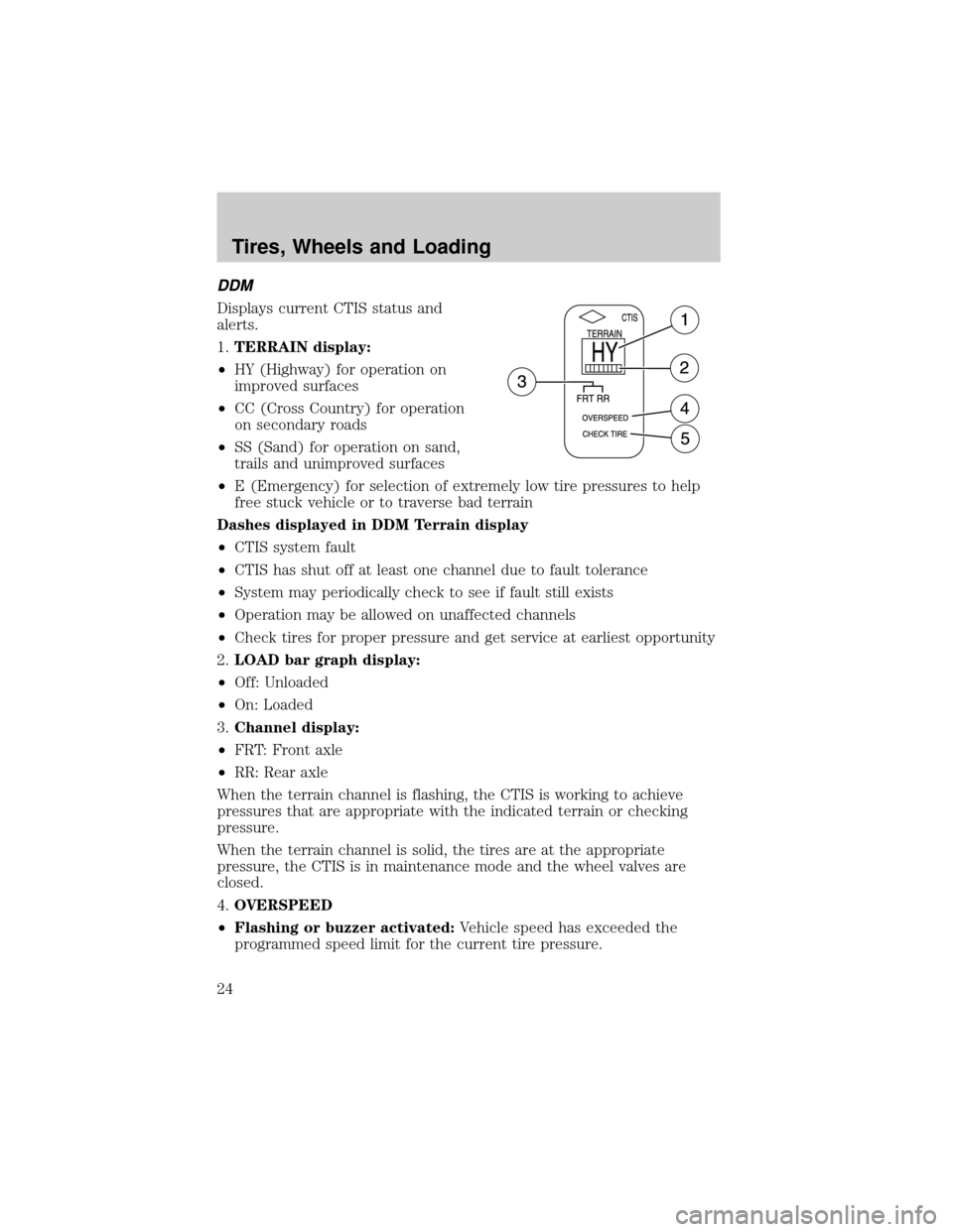
DDM
Displays current CTIS status and
alerts.
1.TERRAIN display:
²HY (Highway) for operation on
improved surfaces
²CC (Cross Country) for operation
on secondary roads
²SS (Sand) for operation on sand,
trails and unimproved surfaces
²E (Emergency) for selection of extremely low tire pressures to help
free stuck vehicle or to traverse bad terrain
Dashes displayed in DDM Terrain display
²CTIS system fault
²CTIS has shut off at least one channel due to fault tolerance
²System may periodically check to see if fault still exists
²Operation may be allowed on unaffected channels
²Check tires for proper pressure and get service at earliest opportunity
2.LOAD bar graph display:
²Off: Unloaded
²On: Loaded
3.Channel display:
²FRT: Front axle
²RR: Rear axle
When the terrain channel is flashing, the CTIS is working to achieve
pressures that are appropriate with the indicated terrain or checking
pressure.
When the terrain channel is solid, the tires are at the appropriate
pressure, the CTIS is in maintenance mode and the wheel valves are
closed.
4.OVERSPEED
²Flashing or buzzer activated:Vehicle speed has exceeded the
programmed speed limit for the current tire pressure.
Tires, Wheels and Loading
24
Page 25 of 28
Note:If the vehicle does not slow down to below the programmed
speed limit, the tires will automatically inflate to the appropriate
higher terrain setting. Once the higher terrain setting has been
achieved, the OVERSPEED light will stop flashing and the buzzer will
stop.
²Solid:The CTIS is not receiving any speed signals.
5.CHECK TIRESFlashes and a buzzer activates when a low tire or a
significant air system leak is detected.
No display lights
²Power out of range
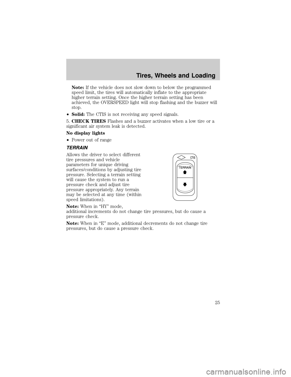
TERRAIN
Allows the driver to select different
tire pressures and vehicle
parameters for unique driving
surfaces/conditions by adjusting tire
pressure. Selecting a terrain setting
will cause the system to run a
pressure check and adjust tire
pressure appropriately. Any terrain
may be selected at any time (within
speed limitations).
Note:When in ªHYº mode,
additional increments do not change tire pressures, but do cause a
pressure check.
Note:When in ªEº mode, additional decrements do not change tire
pressures, but do cause a pressure check.
Tires, Wheels and Loading
25
Page 26 of 28
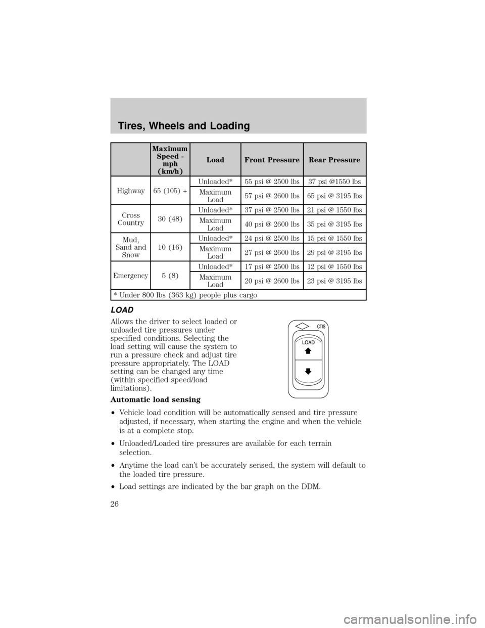
Maximum
Speed -
mph
(km/h)Load Front Pressure Rear Pressure
Highway
65 (105) +
Unloaded*55 psi @ 2500 lbs 37 psi @1550 lbs
Maximum
Load57 psi @ 2600 lbs 65 psi @ 3195 lbs
Cross
Country30 (48)Unloaded*37 psi @ 2500 lbs 21 psi @ 1550 lbs
Maximum
Load40 psi @ 2600 lbs 35 psi @ 3195 lbs
Mud,
Sand and
Snow10 (16)Unloaded*24 psi @ 2500 lbs 15 psi @ 1550 lbs
Maximum
Load27 psi @ 2600 lbs 29 psi @ 3195 lbs
Emergency
5 (8)Unloaded*
17 psi @ 2500 lbs 12 psi @ 1550 lbs
Maximum
Load20 psi @ 2600 lbs 23 psi @ 3195 lbs
* Under 800 lbs (363 kg) people plus cargo
LOAD
Allows the driver to select loaded or
unloaded tire pressures under
specified conditions. Selecting the
load setting will cause the system to
run a pressure check and adjust tire
pressure appropriately. The LOAD
setting can be changed any time
(within specified speed/load
limitations).
Automatic load sensing
²Vehicle load condition will be automatically sensed and tire pressure
adjusted, if necessary, when starting the engine and when the vehicle
is at a complete stop.
²Unloaded/Loaded tire pressures are available for each terrain
selection.
²Anytime the load can't be accurately sensed, the system will default to
the loaded tire pressure.
²Load settings are indicated by the bar graph on the DDM.
Tires, Wheels and Loading
26
Page 27 of 28

Tire pressure maintenance
The CTIS is set to check tire pressure every 15 minutes. The wheel
valves will automatically isolate the tires from the rest of the system; this
prevents a decrease in tire pressure due to fitting and seal leaks.
Some clicking may be heard as the system activates to achieve a new tire
pressure. Adequate supply system air pressure is required to begin or
continue any pressure change.
The system is designed to allow tire pressure increases due to heat
build-up during vehicle use. The system will not deflate the pressure
build-ups, a lower pressure mode selection must be made to decrease
the tire pressure.
Flat tire/Tire leak detection
If the CTIS detects a significantly low tire, the system will display a
ªCHECK TIREº message, sound a buzzer and automatically attempt to
inflate the tire(s) to the selected mode pressure. The ªCHECK TIREº
message and buzzer will stay on until the tire is inflated to the selected
mode pressure.
Tires, Wheels and Loading
27
Page 28 of 28

CHANGING A FLAT TIRE
Refer to yourOwner's Guidefor the tire changing procedure. Follow the
F-350 Dual Rear Wheel (DRW) jacking instructions.
FUSING
Note:Fuse 29 in the instrument panel box, located below and to the left
of the steering wheel, should be a 15A mini fuse. Always replace the fuse
you removed with a fuse with the same amperage rating.
Roadside emergencies
28