FORD SUPER DUTY 2009 2.G Owners Manual
Manufacturer: FORD, Model Year: 2009, Model line: SUPER DUTY, Model: FORD SUPER DUTY 2009 2.GPages: 418, PDF Size: 3.55 MB
Page 141 of 418
The compass reading may be affected when you drive near large
buildings, bridges, power lines and powerful broadcast antenna. Magnetic
or metallic objects placed in, on or near the vehicle may also affect
compass accuracy.
Usually, when something affects the compass readings, the compass will
correct itself after a few days of operating your vehicle in normal
conditions. If the compass still appears to be inaccurate, a manual
calibration may be necessary. Refer toCompass zone/calibration
adjustment.
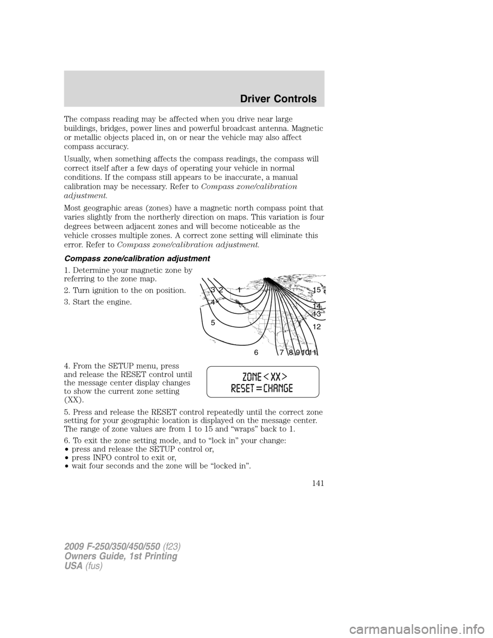
Most geographic areas (zones) have a magnetic north compass point that
varies slightly from the northerly direction on maps. This variation is four
degrees between adjacent zones and will become noticeable as the
vehicle crosses multiple zones. A correct zone setting will eliminate this
error. Refer toCompass zone/calibration adjustment.
Compass zone/calibration adjustment
1. Determine your magnetic zone by
referring to the zone map.
2. Turn ignition to the on position.
3. Start the engine.
4. From the SETUP menu, press
and release the RESET control until
the message center display changes
to show the current zone setting
(XX).
5. Press and release the RESET control repeatedly until the correct zone
setting for your geographic location is displayed on the message center.
The range of zone values are from 1 to 15 and “wraps” back to 1.
6. To exit the zone setting mode, and to “lock in” your change:
•press and release the SETUP control or,
•press INFO control to exit or,
•wait four seconds and the zone will be “locked in”.
1 2 3
4
5
6 7 8 9 101112 13 14 15
2009 F-250/350/450/550(f23)
Owners Guide, 1st Printing
USA(fus)
Driver Controls
141
Page 142 of 418
Perform compass calibration in an open area free from steel structures
and high voltage lines. For optimum calibration, turn off all electrical
accessories (heater/air conditioning, wipers, etc.) and make sure all
vehicle doors are shut.
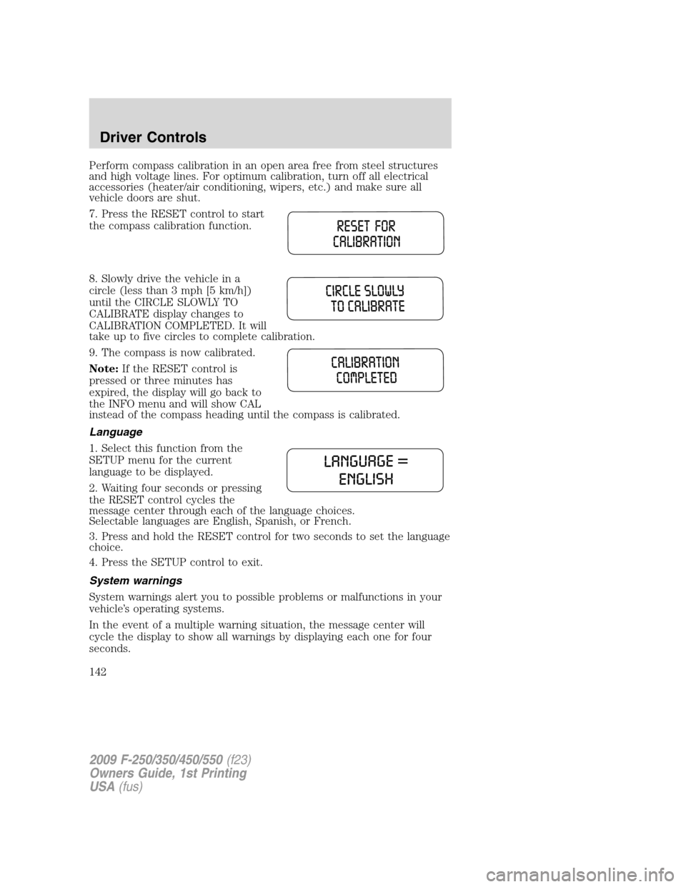
7. Press the RESET control to start
the compass calibration function.
8. Slowly drive the vehicle in a
circle (less than 3 mph [5 km/h])
until the CIRCLE SLOWLY TO
CALIBRATE display changes to
CALIBRATION COMPLETED. It will
take up to five circles to complete calibration.
9. The compass is now calibrated.
Note:If the RESET control is
pressed or three minutes has
expired, the display will go back to
the INFO menu and will show CAL
instead of the compass heading until the compass is calibrated.
Language
1. Select this function from the
SETUP menu for the current
language to be displayed.
2. Waiting four seconds or pressing
the RESET control cycles the
message center through each of the language choices.
Selectable languages are English, Spanish, or French.
3. Press and hold the RESET control for two seconds to set the language
choice.
4. Press the SETUP control to exit.
System warnings
System warnings alert you to possible problems or malfunctions in your
vehicle’s operating systems.
In the event of a multiple warning situation, the message center will
cycle the display to show all warnings by displaying each one for four
seconds.
2009 F-250/350/450/550(f23)
Owners Guide, 1st Printing
USA(fus)
Driver Controls
142
Page 143 of 418
The message center will display the last selected feature if there are no
more warning messages. This allows you to use the full functionality of
the message center after you acknowledge the warning by pressing the
RESET control and clearing the warning message.
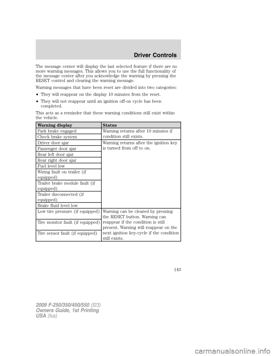
Warning messages that have been reset are divided into two categories:
•They will reappear on the display 10 minutes from the reset.
•They will not reappear until an ignition off-on cycle has been
completed.
This acts as a reminder that these warning conditions still exist within
the vehicle.
Warning display Status
Park brake engaged Warning returns after 10 minutes if
condition still exists.
Check brake system
Driver door ajar Warning returns after the ignition key
is turned from off to on.
Passenger door ajar
Rear left door ajar
Rear right door ajar
Fuel level low
Wiring fault on trailer (if
equipped)
Trailer brake module fault (if
equipped)
Trailer disconnected (if
equipped)
Brake fluid level low
Low tire pressure (if equipped) Warning can be cleared by pressing
the RESET button. Warning can
reappear if the condition is still
present. Warning will reappear on the
next ignition key-cycle if the condition
still exists. Tire monitor fault (if equipped)
Tire sensor fault (if equipped)
2009 F-250/350/450/550(f23)
Owners Guide, 1st Printing
USA(fus)
Driver Controls
143
Page 144 of 418
Warning display Status
Check air filter (diesel engine
only)
Drain water separator (diesel
engine only)
Stop safely now (diesel engine
only)
Engine warming please wait xx
(diesel engine only)
OK to drive (diesel engine
only)
Engine turns off in xx (diesel
engine only)
Engine turned off (diesel
engine only)
Drive to clean exhaust filter
(diesel engine only)
Cleaning exhaust filter (diesel
engine only)
Exhaust filter drive complete
(diesel engine only)
Oil life change soon (gas
engine only)
Oil change required (gas
engine only)
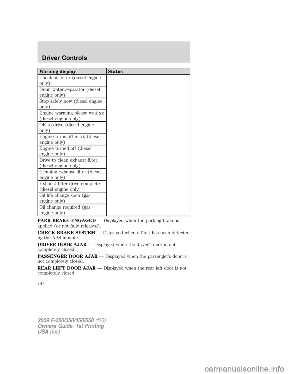
PARK BRAKE ENGAGED— Displayed when the parking brake is
applied (or not fully released).
CHECK BRAKE SYSTEM— Displayed when a fault has been detected
by the ABS module.
DRIVER DOOR AJAR— Displayed when the driver’s door is not
completely closed.
PASSENGER DOOR AJAR— Displayed when the passenger’s door is
not completely closed.
REAR LEFT DOOR AJAR— Displayed when the rear left door is not
completely closed.
2009 F-250/350/450/550(f23)
Owners Guide, 1st Printing
USA(fus)
Driver Controls
144
Page 145 of 418
REAR RIGHT DOOR AJAR— Displayed when the rear right door is
not completely closed.
FUEL LEVEL LOW— Displayed as an early reminder of a low fuel
condition.
WIRING FAULT ON TRAILER (if equipped)— Displayed and
accompanied by a single chime if there are certain faults in the vehicle
wiring and trailer wiring/brake system. Refer toTrailer towingin the
Tires, Wheels and Loadingchapter for more information.
TRAILER BRAKE MODULE FAULT (if equipped)— Displayed and
accompanied by a single chime in response to faults sensed by the TBC.
Refer toTrailer towingin theTires, Wheels and Loadingchapter for
more information.
TRAILER CONNECTED (if equipped)— Displayed when a correct
trailer connection (a trailer with electric trailer brakes) is sensed during
a given ignition cycle. Refer toTrailer towingin theTires, Wheels and
Loadingchapter for more information.
TRAILER DISCONNECTED (if equipped)— Displayed and
accompanied by a single chime when a trailer connection becomes
disconnected, either intentionally or unintentionally, and has been sensed
during a given ignition cycle. Refer toTrailer towingin theTires,
Wheels and Loadingchapter for more information.
BRAKE FLUID LEVEL LOW— Indicates the brake fluid level is low
and the brake system should be inspected immediately. Refer toBrake
fluidin theMaintenance and Specificationschapter.
LOW TIRE PRESSURE (if equipped)— Displayed when one or more
tires on your vehicle have low tire pressure. Refer toInflating Your
Tiresin theTires, Wheels and Loadingchapter.
TIRE PRESSURE MONITOR FAULT (if equipped)— Displayed
when the Tire Pressure Monitoring System is malfunctioning. If the
warning stays on or continues to come on, contact your authorized
dealer as soon as possible.
TIRE PRESSURE SENSOR FAULT (if equipped)— Displayed when
a tire pressure sensor is malfunctioning, or your spare tire is in use. For
more information on how the system operates under these conditions,
refer toUnderstanding Your Tire Pressure Monitoring System
(TPMS)in theTires, Wheels and Loadingchapter. If the warning stays
on or continues to come on, contact your authorized dealer as soon as
possible.
CHECK AIR FILTER (Diesel engine only)— Refer toInstrument
Clusterin your6.0 and 6.4 Liter Power Stroke Direct Injection Turbo
Diesel Owner’s Guide Supplement.
2009 F-250/350/450/550(f23)
Owners Guide, 1st Printing
USA(fus)
Driver Controls
145
Page 146 of 418
DRAIN WATER SEPARATOR (Diesel engine only)— Displayed
when the water separator has reached a predetermined capacity and
needs to be drained. Refer to your6.0 and 6.4 Liter Power Stroke
Direct Injection Turbo Diesel Owner’s Guide Supplementfor more
information.
STOP SAFELY NOW (Diesel engine only)— Displays and a chime
sounds when the vehicle exhaust system temperature exceeds intended
operating range. If this warning occurs, the engine power is reduced and
the engine will shutdown when the vehicle speed is below 3 mph
(5 km/h).Stop the vehicle as soon as safely possibleand contact
your authorized dealer. Depending on the severity of the
over-temperature condition, the vehicle may or may not restart after
cycling the ignition off. If the vehicle restarts, there may be limited
power, or there could be full function. If the exhaust over-temperature
condition reoccurs the message center will display, STOP SAFELY NOW,
the chime will sound, the engine power will be reduced again and shut
down below 3 mph (5km/h).
ENGINE TURNS OFF IN XX (Diesel engine only)— Displayed
when the vehicle is in the final 30 seconds of a countdown to where the
engine will intentionally be turned off by the PCM. The diesel engine
shutdown is a (Regulatory) requirement which may be required of a
particular diesel vehicle for sale in States requiring this feature.
ENGINE TURNED OFF (Diesel engine only)— Displayed after the
30 second countdown.
ENGINE WARMING PLEASE WAIT XX (Diesel engine only)—
Displayed in extremely cold weather; typically around –15°F (–26°C).
The accelerator pedal will not respond to pressing; this is done so the
engine oil can be properly circulated to avoid engine damage from lack
of lubrication. A timer will begin a countdown from 30 seconds, then OK
TO DRIVE will display once the counter has reached 0 (zero) and the
accelerator pedal will respond to pressing.
OK TO DRIVE (Diesel engine only)— Displayed when the time
counter has reached 0 (zero) and the engine is sufficiently warm enough
to drive in extremely cold weather (refer to the ENGINE WARMING
description mentioned previously).
DRIVE TO CLEAN EXHAUST FILTER (Diesel engine only)—
Displayed when the engine control module detects the Diesel Particulate
Filter (DPF) is full of particulates and that the vehicle is not being
operated in a manner to allow automatic cleaning. The vehicle operator
will have to drive the vehicle above 30 mph (48 km/h) for at least
2009 F-250/350/450/550(f23)
Owners Guide, 1st Printing
USA(fus)
Driver Controls
146
Page 147 of 418
20 minutes to clean the DPF. This message will continue to be displayed
until an adequate drive cycle is completed. This message is NORMAL.
Note:Power-Take-Off (PTO) and/or Stationary Elevated Idle (SEIC)
must be disabled in order to initiate Diesel Particulate Filter (DPF)
cleaning.
CLEANING EXHAUST FILTER (Diesel engine only)— Displays
continuously when the vehicle has entered the cleaning mode normally;
or when cleaning the filter after a DRIVE TO CLEAN EXHAUST FILTER
message was previously displayed. When this message is displayed
various engine actions will raise the exhaust temperature in the DPF to
clean the exhaust filter. After the exhaust filter is cleaned, the exhaust
temperature will fall back to normal levels. This message is NORMAL.
WARNING:When the CLEANING EXHAUST FILTER message
appears in the message center do not park near flammable
materials, vapors and structures until filter cleaning is complete.
EXHAUST FILTER DRIVE COMPLETE (Diesel engine only)—
Displayed when the vehicle has completed the adequate drive cycle to
clean the DPF. This message is NORMAL.
WARNING:Do not park, idle, or drive your vehicle in dry grass
or other dry ground cover. The emission system heats up the
engine compartment and exhaust system, which can start a fire.
OIL LIFE CHANGE SOON (Gas engine only)— Displayed when the
engine oil life remaining is 5 percent or less. When oil life left is between
5% and 0%, the ENGINE OIL CHANGE SOON message will be displayed.
OIL CHANGE REQUIRED (Gas engine only)— Displayed when the
oil life left reaches 0%, the OIL CHANGE REQUIRED message will be
displayed. OIL LIFE OK displays after you have changed the oil.
2009 F-250/350/450/550(f23)
Owners Guide, 1st Printing
USA(fus)
Driver Controls
147
Page 148 of 418
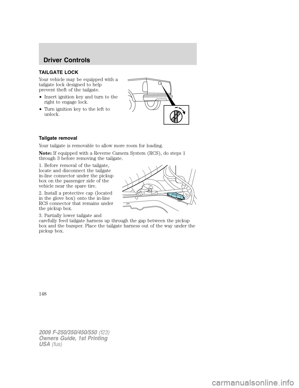
TAILGATE LOCK
Your vehicle may be equipped with a
tailgate lock designed to help
prevent theft of the tailgate.
•Insert ignition key and turn to the
right to engage lock.
•Turn ignition key to the left to
unlock.
Tailgate removal
Your tailgate is removable to allow more room for loading.
Note:If equipped with a Reverse Camera System (RCS), do steps 1
through 3 before removing the tailgate.
1. Before removal of the tailgate,
locate and disconnect the tailgate
in-line connector under the pickup
box on the passenger side of the
vehicle near the spare tire.
2. Install a protective cap (located
in the glove box) onto the in-line
RCS connector that remains under
the pickup box.
3. Partially lower tailgate and
carefully feed tailgate harness up through the gap between the pickup
box and the bumper. Place the tailgate harness out of the way under the
pickup box.
2009 F-250/350/450/550(f23)
Owners Guide, 1st Printing
USA(fus)
Driver Controls
148
Page 149 of 418
4. Lower the tailgate.
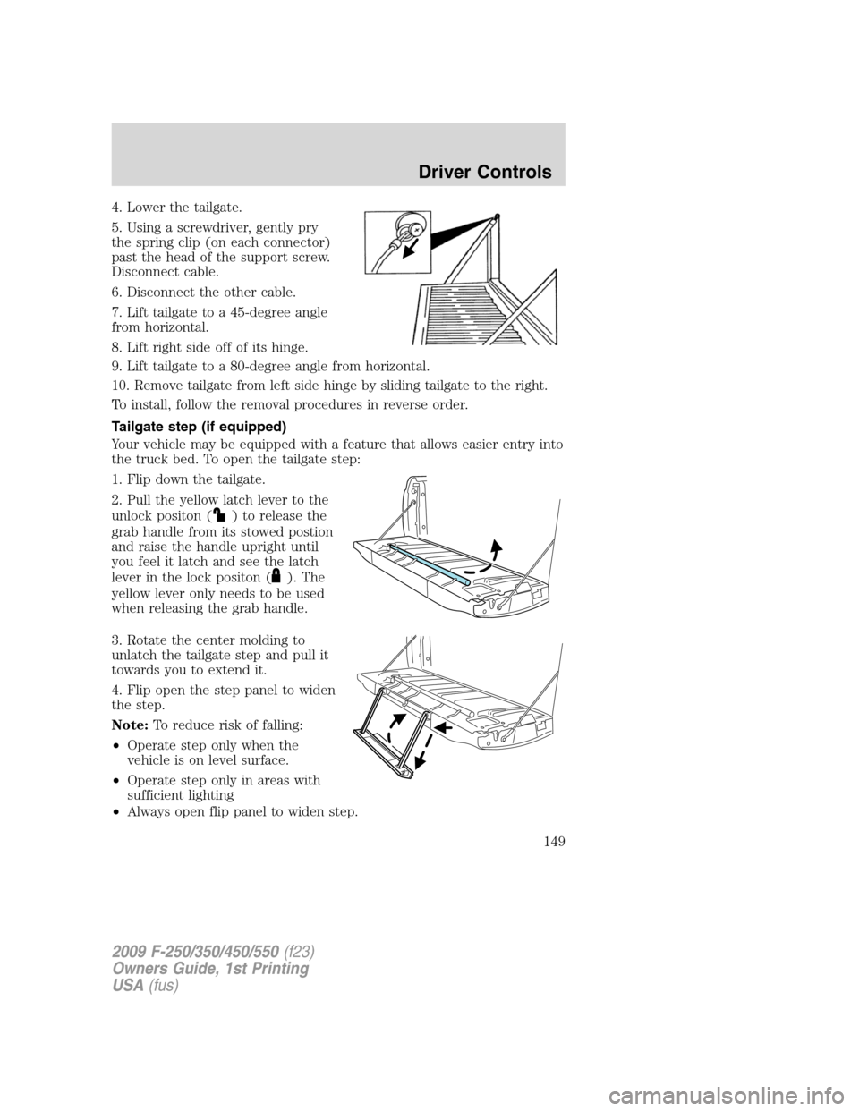
5. Using a screwdriver, gently pry
the spring clip (on each connector)
past the head of the support screw.
Disconnect cable.
6. Disconnect the other cable.
7. Lift tailgate to a 45-degree angle
from horizontal.
8. Lift right side off of its hinge.
9. Lift tailgate to a 80-degree angle from horizontal.
10. Remove tailgate from left side hinge by sliding tailgate to the right.
To install, follow the removal procedures in reverse order.
Tailgate step (if equipped)
Your vehicle may be equipped with a feature that allows easier entry into
the truck bed. To open the tailgate step:
1. Flip down the tailgate.
2. Pull the yellow latch lever to the
unlock positon (
) to release the
grab handle from its stowed postion
and raise the handle upright until
you feel it latch and see the latch
lever in the lock positon (
). The
yellow lever only needs to be used
when releasing the grab handle.
3. Rotate the center molding to
unlatch the tailgate step and pull it
towards you to extend it.
4. Flip open the step panel to widen
the step.
Note:To reduce risk of falling:
•Operate step only when the
vehicle is on level surface.
•Operate step only in areas with
sufficient lighting
•Always open flip panel to widen step.
2009 F-250/350/450/550(f23)
Owners Guide, 1st Printing
USA(fus)
Driver Controls
149
Page 150 of 418
•Always use grab handle when stepping up and down.
•Step not intended for bare-footed use.
•Keep step clean from contamination before use (e.g. snow, mud)
•Keep the step load (you + load) below 350 lb. (159 kg).
•Never drive with step deployed.
To close the tailgate step:
1. Close the step panel, then lift and fully close the tailgate step into the
tailgate.
2. Slide the latch at the bottom of the handle, then lower the handle.
Note:
•Fully close and latch the tailgate step before moving the vehicle.
•Never drive with the step or grab handle deployed.
•Replace slip resistance tape (serviceable item) if worn out.
•Replace handle molding (serviceable item) if damaged.
•Do not tow with grab handle or step frame.
Bed extender (if equipped)
Your vehicle may be equipped with a cargo management feature in the
truck bed.
Note:This feature is not intended for off-road usage.
To open the bed extender into tailgate mode:
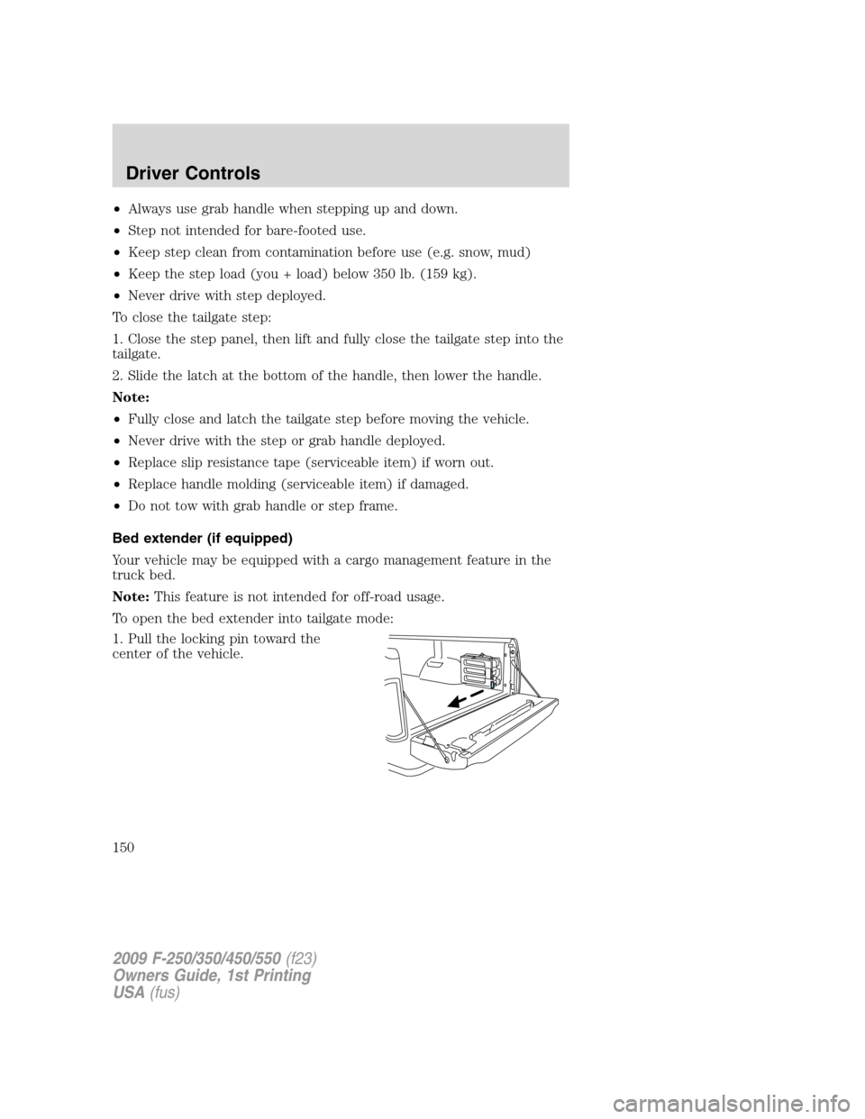
1. Pull the locking pin toward the
center of the vehicle.
2009 F-250/350/450/550(f23)
Owners Guide, 1st Printing
USA(fus)
Driver Controls
150