FORD SUPER DUTY 2017 4.G Owners Manual
Manufacturer: FORD, Model Year: 2017, Model line: SUPER DUTY, Model: FORD SUPER DUTY 2017 4.GPages: 636, PDF Size: 10.56 MB
Page 351 of 636
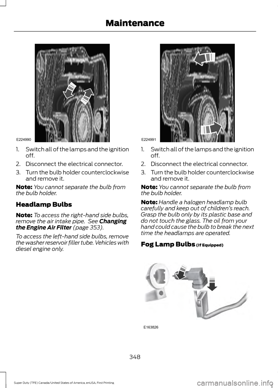
1.
Switch all of the lamps and the ignition
off.
2. Disconnect the electrical connector.
3. Turn the bulb holder counterclockwise
and remove it.
Note: You cannot separate the bulb from
the bulb holder.
Headlamp Bulbs
Note: To access the right-hand side bulbs,
remove the air intake pipe. See Changing
the Engine Air Filter (page 353).
To access the left-hand side bulbs, remove
the washer reservoir filler tube. Vehicles with
diesel engine only. 1.
Switch all of the lamps and the ignition
off.
2. Disconnect the electrical connector.
3. Turn the bulb holder counterclockwise
and remove it.
Note: You cannot separate the bulb from
the bulb holder.
Note: Handle a halogen headlamp bulb
carefully and keep out of children ’s reach.
Grasp the bulb only by its plastic base and
do not touch the glass. The oil from your
hand could cause the bulb to break the next
time the headlamps are operated.
Fog Lamp Bulbs
(If Equipped) 348
Super Duty (TFE) Canada/United States of America, enUSA, First Printing MaintenanceE224990 E224991 E163826
Page 352 of 636
1.
Switch all of the lamps and the ignition
off.
2. To access the bulb, reach behind the bumper.
3. Disconnect the electrical connector.
4. Turn the bulb holder counterclockwise
and remove it.
Note: You cannot separate the bulb from
the bulb holder.
Note: Handle a halogen bulb carefully and
keep out of children ’s reach. Grasp the bulb
only by its plastic base and do not touch the
glass. The oil from your hand could cause
the bulb to break the next time the fog
lamps are operated.
Rear Lamps, Brake Lamps, Rear
Direction Indicator and Reversing
Lamp Bulbs
Pickup Models - Vehicles without Blind
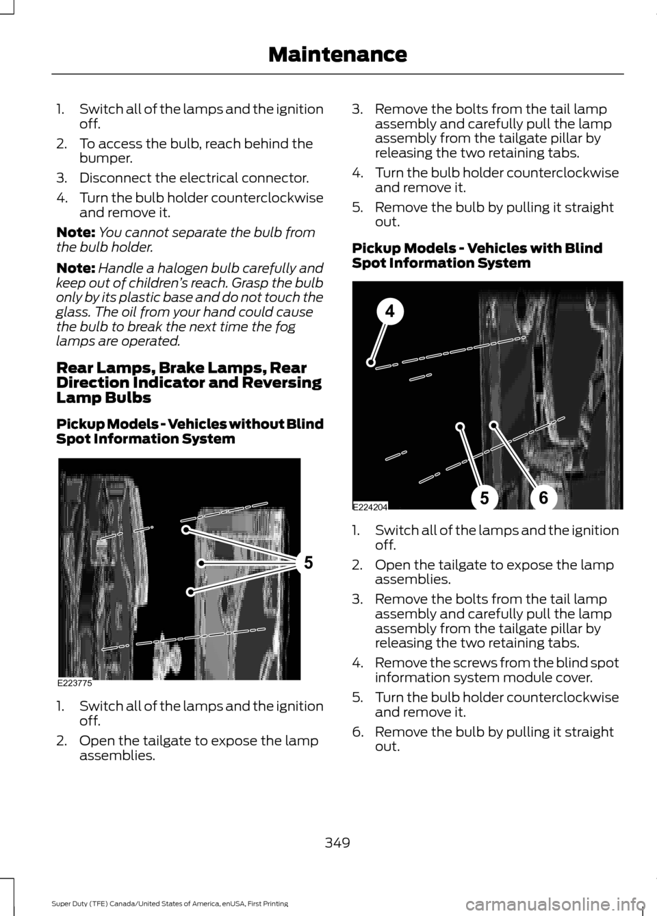
Spot Information System 1.
Switch all of the lamps and the ignition
off.
2. Open the tailgate to expose the lamp assemblies. 3. Remove the bolts from the tail lamp
assembly and carefully pull the lamp
assembly from the tailgate pillar by
releasing the two retaining tabs.
4. Turn the bulb holder counterclockwise
and remove it.
5. Remove the bulb by pulling it straight out.
Pickup Models - Vehicles with Blind
Spot Information System 1.
Switch all of the lamps and the ignition
off.
2. Open the tailgate to expose the lamp assemblies.
3. Remove the bolts from the tail lamp assembly and carefully pull the lamp
assembly from the tailgate pillar by
releasing the two retaining tabs.
4. Remove the screws from the blind spot
information system module cover.
5. Turn the bulb holder counterclockwise
and remove it.
6. Remove the bulb by pulling it straight out.
349
Super Duty (TFE) Canada/United States of America, enUSA, First Printing MaintenanceE223775
5 E224204
4
65
Page 353 of 636
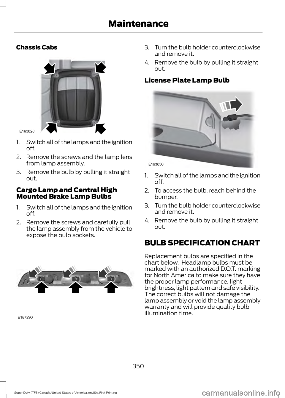
Chassis Cabs
1.
Switch all of the lamps and the ignition
off.
2. Remove the screws and the lamp lens from lamp assembly.
3. Remove the bulb by pulling it straight out.
Cargo Lamp and Central High
Mounted Brake Lamp Bulbs
1. Switch all of the lamps and the ignition
off.
2. Remove the screws and carefully pull the lamp assembly from the vehicle to
expose the bulb sockets. 3.
Turn the bulb holder counterclockwise
and remove it.
4. Remove the bulb by pulling it straight out.
License Plate Lamp Bulb 1.
Switch all of the lamps and the ignition
off.
2. To access the bulb, reach behind the bumper.
3. Turn the bulb holder counterclockwise
and remove it.
4. Remove the bulb by pulling it straight out.
BULB SPECIFICATION CHART
Replacement bulbs are specified in the
chart below. Headlamp bulbs must be
marked with an authorized D.O.T. marking
for North America to make sure they have
the proper lamp performance, light
brightness, light pattern and safe visibility.
The correct bulbs will not damage the
lamp assembly or void the lamp assembly
warranty and will provide quality bulb
illumination time.
350
Super Duty (TFE) Canada/United States of America, enUSA, First Printing MaintenanceE163828 E187290 E163830
Page 354 of 636
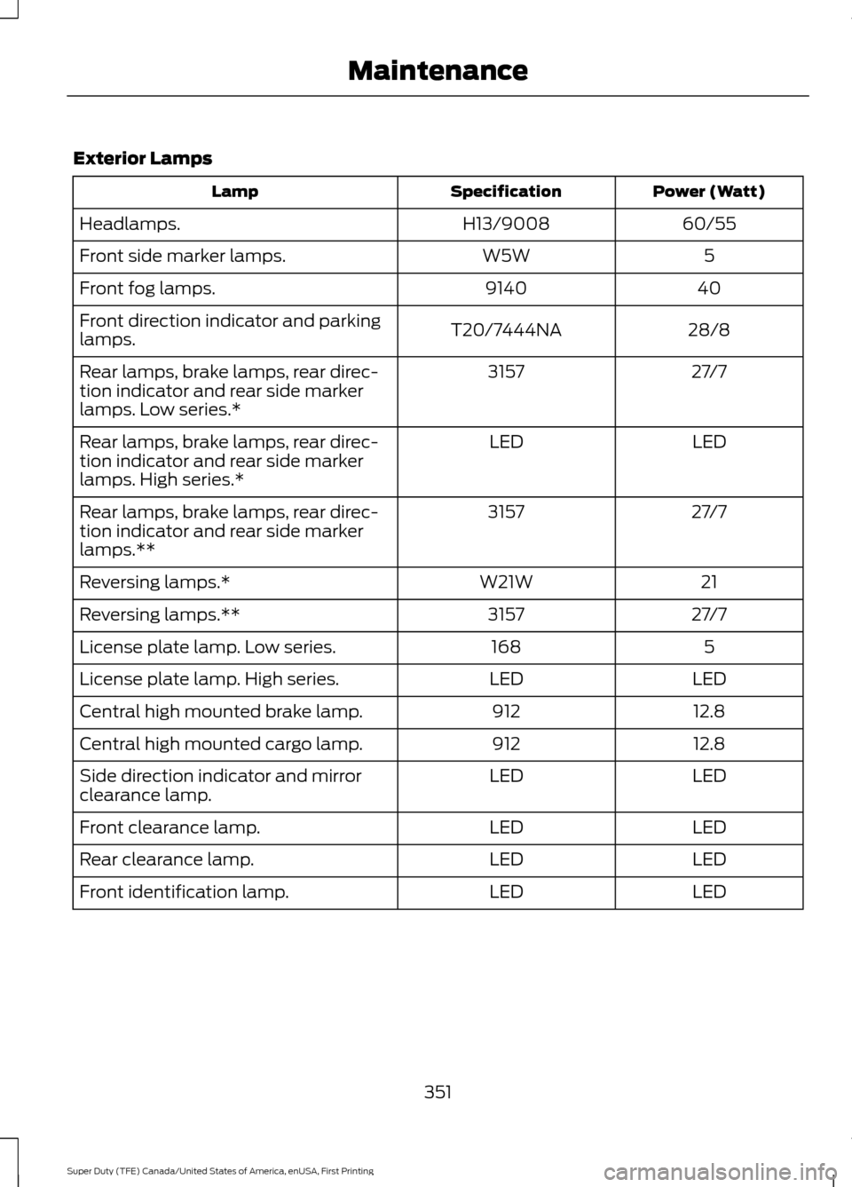
Exterior Lamps
Power (Watt)
Specification
Lamp
60/55
H13/9008
Headlamps.
5
W5W
Front side marker lamps.
40
9140
Front fog lamps.
28/8
T20/7444NA
Front direction indicator and parking
lamps.
27/7
3157
Rear lamps, brake lamps, rear direc-
tion indicator and rear side marker
lamps. Low series.*
LED
LED
Rear lamps, brake lamps, rear direc-
tion indicator and rear side marker
lamps. High series.*
27/7
3157
Rear lamps, brake lamps, rear direc-
tion indicator and rear side marker
lamps.**
21
W21W
Reversing lamps.*
27/7
3157
Reversing lamps.**
5
168
License plate lamp. Low series.
LED
LED
License plate lamp. High series.
12.8
912
Central high mounted brake lamp.
12.8
912
Central high mounted cargo lamp.
LED
LED
Side direction indicator and mirror
clearance lamp.
LED
LED
Front clearance lamp.
LED
LED
Rear clearance lamp.
LED
LED
Front identification lamp.
351
Super Duty (TFE) Canada/United States of America, enUSA, First Printing Maintenance
Page 355 of 636
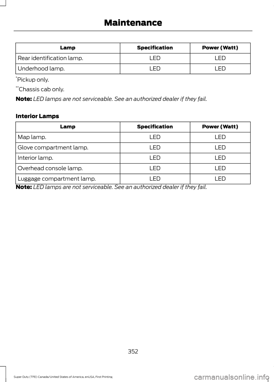
Power (Watt)
Specification
Lamp
LED
LED
Rear identification lamp.
LED
LED
Underhood lamp.
* Pickup only.
** Chassis cab only.
Note: LED lamps are not serviceable. See an authorized dealer if they fail.
Interior Lamps Power (Watt)
Specification
Lamp
LED
LED
Map lamp.
LED
LED
Glove compartment lamp.
LED
LED
Interior lamp.
LED
LED
Overhead console lamp.
LED
LED
Luggage compartment lamp.
Note: LED lamps are not serviceable. See an authorized dealer if they fail.
352
Super Duty (TFE) Canada/United States of America, enUSA, First Printing Maintenance
Page 356 of 636
CHANGING THE ENGINE AIR
FILTER - 6.2L/6.8L
WARNING
To reduce the risk of vehicle damage
and personal burn injuries, do not
start your engine with the air cleaner
removed and do not remove it while the
engine is running. Use the correct specification air filter
element. See Motorcraft Parts (page
414).
Note: Failure to use the correct air filter
element may result in severe engine
damage. Resulting component damage
may not be covered by the vehicle Warranty.
Change the air filter element at the correct
service interval. See
Scheduled
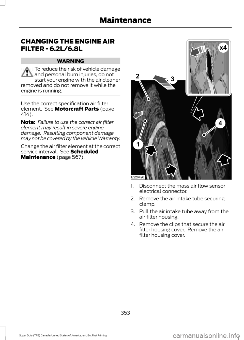
Maintenance (page 567). 1. Disconnect the mass air flow sensor
electrical connector.
2. Remove the air intake tube securing clamp.
3. Pull the air intake tube away from the air filter housing.
4. Remove the clips that secure the air filter housing cover. Remove the air
filter housing cover.
353
Super Duty (TFE) Canada/United States of America, enUSA, First Printing MaintenanceE226426
x4
1
2
4
3
Page 357 of 636
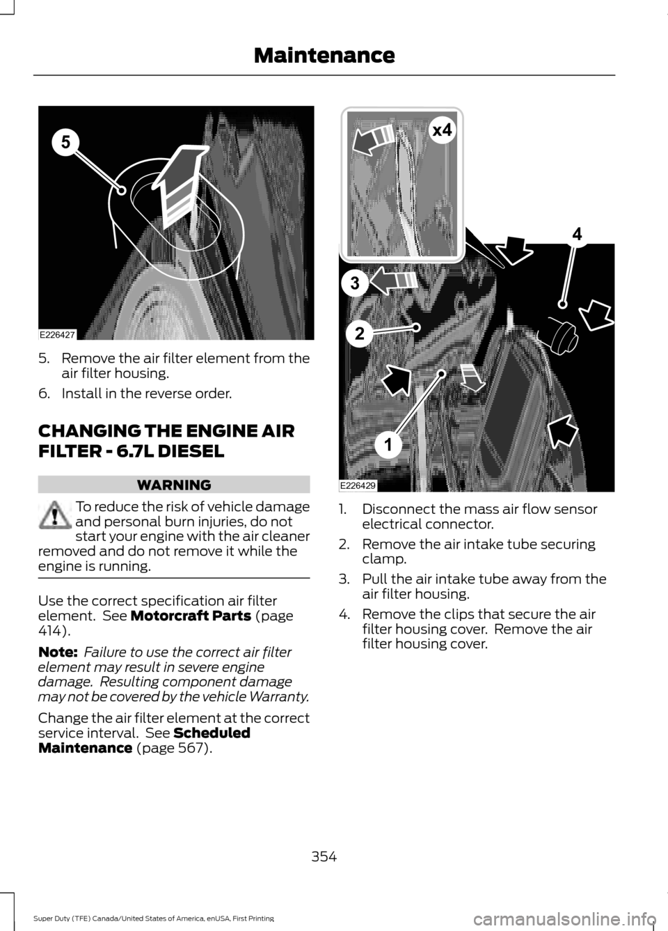
5.
Remove the air filter element from the
air filter housing.
6. Install in the reverse order.
CHANGING THE ENGINE AIR
FILTER - 6.7L DIESEL WARNING
To reduce the risk of vehicle damage
and personal burn injuries, do not
start your engine with the air cleaner
removed and do not remove it while the
engine is running. Use the correct specification air filter
element. See Motorcraft Parts (page
414).
Note: Failure to use the correct air filter
element may result in severe engine
damage. Resulting component damage
may not be covered by the vehicle Warranty.
Change the air filter element at the correct
service interval. See
Scheduled
Maintenance (page 567). 1. Disconnect the mass air flow sensor
electrical connector.
2. Remove the air intake tube securing clamp.
3. Pull the air intake tube away from the air filter housing.
4. Remove the clips that secure the air filter housing cover. Remove the air
filter housing cover.
354
Super Duty (TFE) Canada/United States of America, enUSA, First Printing MaintenanceE226427
5 1
2
4
3
E226429
x4
Page 358 of 636
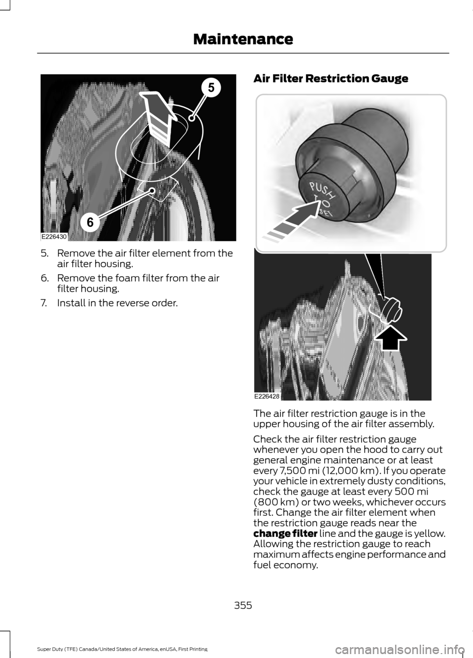
5.
Remove the air filter element from the
air filter housing.
6. Remove the foam filter from the air filter housing.
7. Install in the reverse order. Air Filter Restriction Gauge
The air filter restriction gauge is in the
upper housing of the air filter assembly.
Check the air filter restriction gauge
whenever you open the hood to carry out
general engine maintenance or at least
every 7,500 mi (12,000 km). If you operate
your vehicle in extremely dusty conditions,
check the gauge at least every 500 mi
(800 km) or two weeks, whichever occurs
first. Change the air filter element when
the restriction gauge reads near the
change filter line and the gauge is yellow.
Allowing the restriction gauge to reach
maximum affects engine performance and
fuel economy.
355
Super Duty (TFE) Canada/United States of America, enUSA, First Printing MaintenanceE226430
5
6 E226428
Page 359 of 636
Operating your vehicle in heavy snowfall
or extreme rain conditions may allow
excessive amounts of snow or water into
the air intake system. This could restrict air
flow and cause the engine to lose power
or shut down.
After installing a new air filter element, you
must reset the gauge by pressing the reset
button.
After operating your vehicle during in heavy
snowfall or extreme rain, do the following:
•
Snow: At the earliest opportunity, open
the hood and clear any snow and ice
from the air filter housing inlet and
reset the air filter restriction gauge.
• Extreme rain: The air filter element
dries out after approximately 15– 30
minutes of driving at highway speeds.
At the earliest opportunity, open the
hood and reset the air filter restriction
gauge.
Note: Do not remove the foam filter.
CHANGING THE ENGINE-
MOUNTED AND DIESEL FUEL
CONDITIONER MODULE FUEL
FILTERS - 6.7L DIESEL WARNING
Do not dispose of fuel in the
household refuse or the public
sewage system. Use an authorized
waste disposal facility. Your vehicle has two fuel filters. The first
filter mounts on top of the engine on the
left-hand side. The second filter is inside
the diesel fuel conditioner module. The
module is mounted between the outboard
side of the fuel tank and the frame rail.
Note:
The module is at the front of the fuel
tank or at the front of the aft-axle fuel tank
on some models. Regular fuel filter changes are an
important part of engine maintenance;
failing to keep with the scheduled
maintenance could lead to engine
performance issues and fuel injection
system damage. See Scheduled
Maintenance (page 567).
Use only recommended service parts
conforming to specifications. See
Motorcraft Parts
(page 415).
Note: Using fuel that has high levels of
impurities may require more frequent filter
replacements than the service interval
specifies.
Diesel Fuel Conditioner Module
Filter
Removal
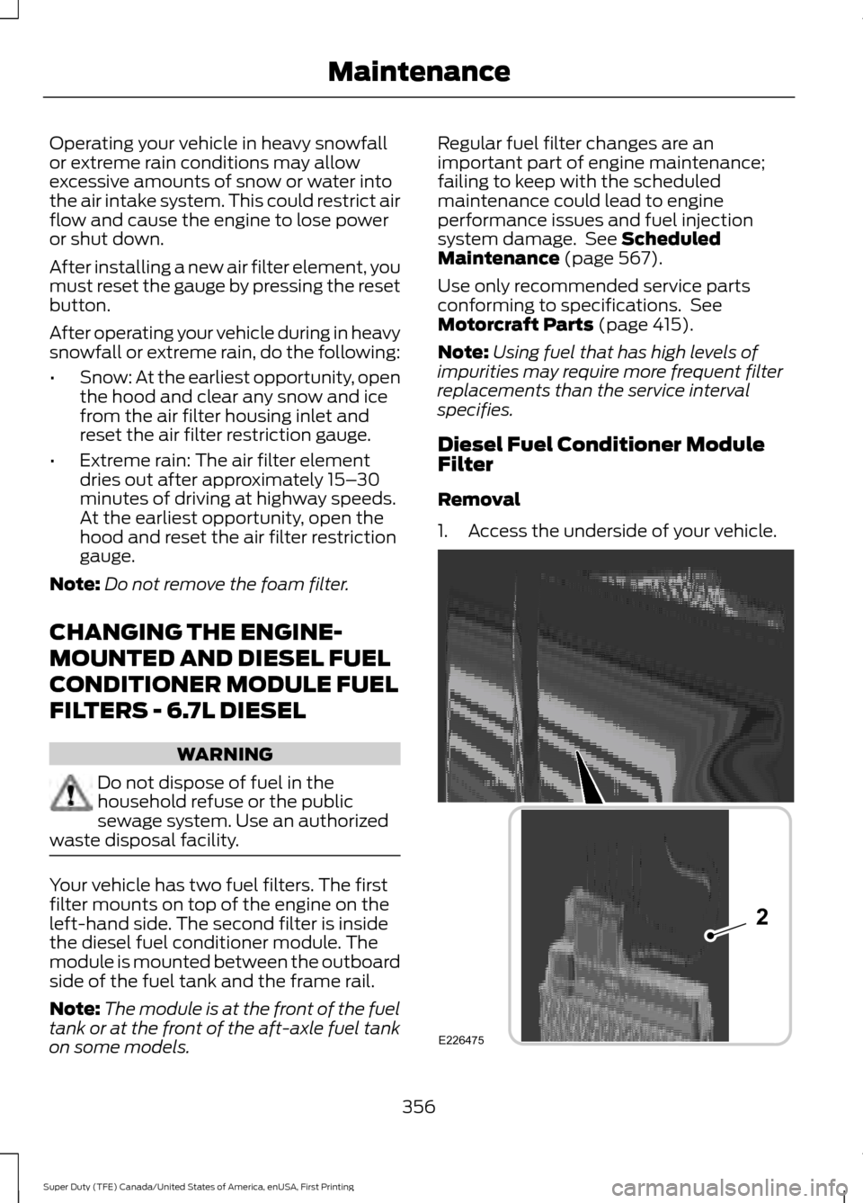
1. Access the underside of your vehicle. 356
Super Duty (TFE) Canada/United States of America, enUSA, First Printing MaintenanceE226475
2
Page 360 of 636
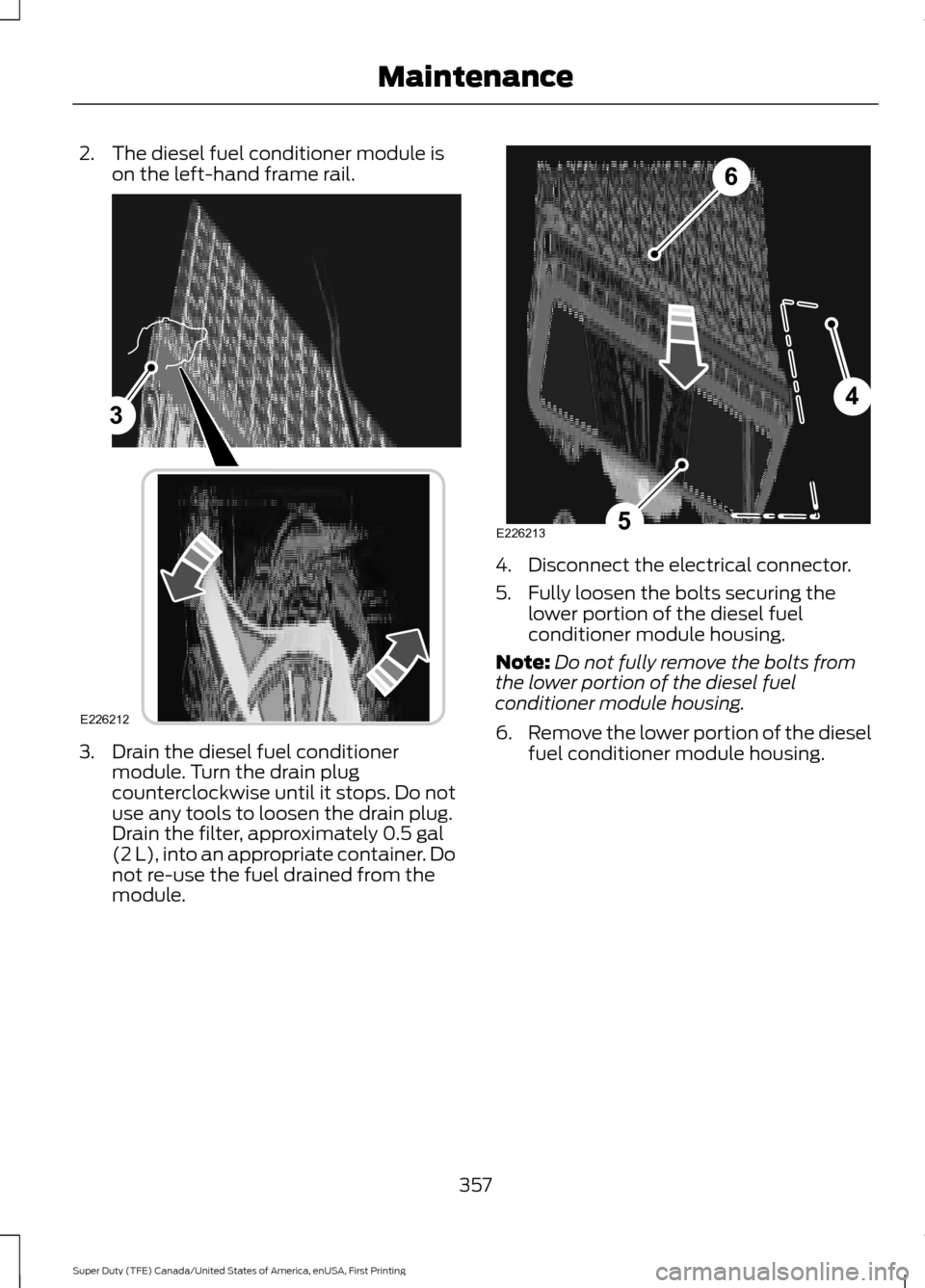
2. The diesel fuel conditioner module is
on the left-hand frame rail. 3. Drain the diesel fuel conditioner
module. Turn the drain plug
counterclockwise until it stops. Do not
use any tools to loosen the drain plug.
Drain the filter, approximately 0.5 gal
(2 L), into an appropriate container. Do
not re-use the fuel drained from the
module. 4. Disconnect the electrical connector.
5. Fully loosen the bolts securing the
lower portion of the diesel fuel
conditioner module housing.
Note: Do not fully remove the bolts from
the lower portion of the diesel fuel
conditioner module housing.
6. Remove the lower portion of the diesel
fuel conditioner module housing.
357
Super Duty (TFE) Canada/United States of America, enUSA, First Printing Maintenance3
E226212 4
5
6
E226213