FORD TAURUS 1999 3.G Owners Manual
Manufacturer: FORD, Model Year: 1999, Model line: TAURUS, Model: FORD TAURUS 1999 3.GPages: 224, PDF Size: 1.42 MB
Page 121 of 224
Safety chains
Always connect the trailer's safety chains to the
vehicle. To connect the trailer's safety chains, cross
the chains under the trailer tongue and allow slack
for turning corners.
If you use a rental trailer, follow the instructions that
the rental agency gives to you.
Do not attach safety chains to the bumper.
Trailer brakes
Electric brakes and manual, automatic or surge-type
brakes are safe if installed properly and adjusted to
the manufacturer's specifications. The trailer brakes
must meet local and Federal regulations.
Do not connect a trailer's hydraulic brake
system directly to your vehicle's brake
system. Your vehicle may not have enough braking
power and your chances of having a collision
greatly increase.
The braking system of the tow vehicle is rated for
operation at the GVWR not GCWR.
Trailer lamps
Trailer lamps are required on most towed vehicles.
Make sure your trailer lamps conform to local and
Federal regulations. See your dealer or trailer rental
agency for proper instructions and equipment for
hooking up trailer lamps.
Driving while you tow
Do not drive faster than 88 km/h (55 mph) when
towing a trailer. Do not drive faster than 72 km/h
(45 mph) with any weight on the trailer while
towing on a hot day or in hilly country.
Speed control may shut off if you are towing on
long, steep grades.
Driving
121
Page 122 of 224
When towing a trailer:
²Use D (Drive) or a lower gear when towing up or
down steep hills. This will eliminate excessive
downshifting and upshifting for optimum fuel
economy and transaxle cooling.
²Anticipate stops and brake gradually.
Servicing after towing
If you tow a trailer for long distances, your vehicle
will require more frequent service intervals. Refer to
your maintenance guide and or service guide for
more information.
Trailer towing tips
²Practice turning, stopping and backing up in an
area before starting on a trip to get the feel of the
vehicle trailer combination. When turning, make
wider turns so the trailer wheels will clear curbs
and other obstacles.
²Allow more distance for stopping with a trailer
attached.
²The trailer tongue weight should be 10% of the
loaded trailer weight.
²After you have traveled 80 km (50 miles),
thoroughly check your hitch, electrical
connections and trailer wheel lug nuts.
²When stopped in traffic for long periods of time in
hot weather, place the gearshift in P (Park) and
increase idle speed. This aids engine cooling and
air conditioner efficiency.
²Vehicles with trailers should not be parked on a
grade. If you must park on a grade, place wheel
chocks under the trailer's wheels.
Towing your vehicle behind another vehicle
At times, you may want to tow your vehicle behind
another vehicle, such as a recreational vehicle, car
or a truck.
Driving
122
Page 123 of 224
Before you have your vehicle towed:
²Release the parking brake.
²Turn the key in the ignition to OFF.
²Move the gearshift to N (Neutral).
²Unlock the steering wheel.
Do not tow your vehicle at a speed faster than
56 km/h (35 mph) or for a distance greater than 80
km (50 miles), unless the drive wheels are placed on
dollies.
Never use a tow bar that attaches to the
bumper when you tow your vehicle. This
could damage the bumper and cause an accident.
LUGGAGE RACK (IF EQUIPPED)
The rear crossbar can be adjusted to fit the item
being carried. The front crossbar does not move. Do
not load more than 44 kg (100 lbs.) on the luggage
rack.
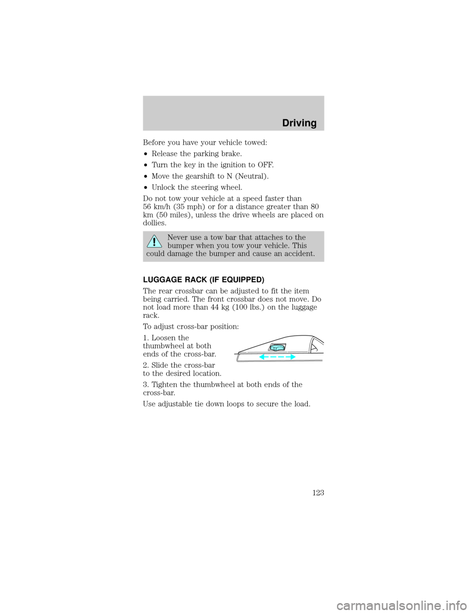
To adjust cross-bar position:
1. Loosen the
thumbwheel at both
ends of the cross-bar.
2. Slide the cross-bar
to the desired location.
3. Tighten the thumbwheel at both ends of the
cross-bar.
Use adjustable tie down loops to secure the load.
Driving
123
Page 124 of 224
HAZARD FLASHER
Use only in an emergency to warn traffic of vehicle
breakdown, approaching danger, etc. The hazard
flashers can be operated when the ignition is off.
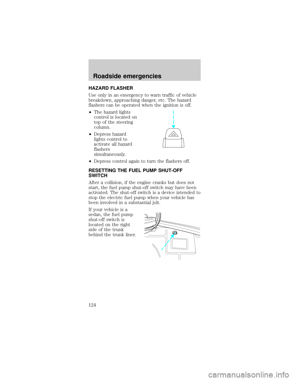
²The hazard lights
control is located on
top of the steering
column.
²Depress hazard
lights control to
activate all hazard
flashers
simultaneously.
²Depress control again to turn the flashers off.
RESETTING THE FUEL PUMP SHUT-OFF
SWITCH
After a collision, if the engine cranks but does not
start, the fuel pump shut-off switch may have been
activated. The shut-off switch is a device intended to
stop the electric fuel pump when your vehicle has
been involved in a substantial jolt.
If your vehicle is a
sedan, the fuel pump
shut-off switch is
located on the right
side of the trunk
behind the trunk liner.
Roadside emergencies
124
Page 125 of 224
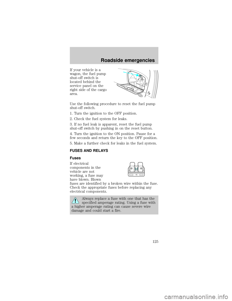
If your vehicle is a
wagon, the fuel pump
shut-off switch is
located behind the
service panel on the
right side of the cargo
area.
Use the following procedure to reset the fuel pump
shut-off switch.
1. Turn the ignition to the OFF position.
2. Check the fuel system for leaks.
3. If no fuel leak is apparent, reset the fuel pump
shut-off switch by pushing in on the reset button.
4. Turn the ignition to the ON position. Pause for a
few seconds and return the key to the OFF position.
5. Make a further check for leaks in the fuel system.
FUSES AND RELAYS
Fuses
If electrical
components in the
vehicle are not
working, a fuse may
have blown. Blown
fuses are identified by a broken wire within the fuse.
Check the appropriate fuses before replacing any
electrical components.
Always replace a fuse with one that has the
specified amperage rating. Using a fuse with
a higher amperage rating can cause severe wire
damage and could start a fire.
15
Roadside emergencies
125
Page 126 of 224
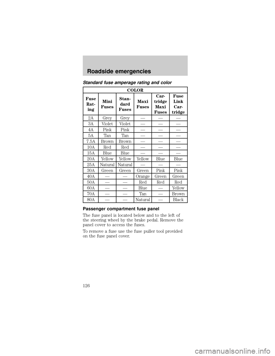
Standard fuse amperage rating and color
COLOR
Fuse
Rat-
ingMini
FusesStan-
dard
FusesMaxi
FusesCar-
tridge
Maxi
FusesFuse
Link
Car-
tridge
2A Grey Grey Ð Ð Ð
3A Violet Violet Ð Ð Ð
4A Pink Pink Ð Ð Ð
5A Tan Tan Ð Ð Ð
7.5A Brown Brown Ð Ð Ð
10A Red Red Ð Ð Ð
15A Blue Blue Ð Ð Ð
20A Yellow Yellow Yellow Blue Blue
25A Natural Natural Ð Ð Ð
30A Green Green Green Pink Pink
40A Ð Ð Orange Green Green
50A Ð Ð Red Red Red
60A Ð Ð Blue Ð Yellow
70A Ð Ð Tan Ð Brown
80A Ð Ð Natural Ð Black
Passenger compartment fuse panel
The fuse panel is located below and to the left of
the steering wheel by the brake pedal. Remove the
panel cover to access the fuses.
To remove a fuse use the fuse puller tool provided
on the fuse panel cover.
Roadside emergencies
126
Page 127 of 224
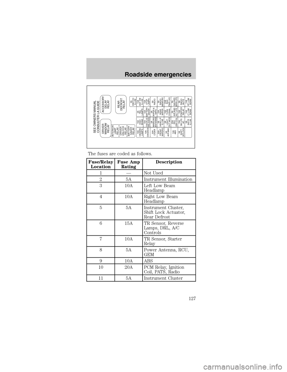
The fuses are coded as follows.
Fuse/Relay
LocationFuse Amp
RatingDescription
1 Ð Not Used
2 5A Instrument Illumination
3 10A Left Low Beam
Headlamp
4 10A Right Low Beam
Headlamp
5 5A Instrument Cluster,
Shift Lock Actuator,
Rear Defrost
6 15A TR Sensor, Reverse
Lamps, DRL, A/C
Controls
7 10A TR Sensor, Starter
Relay
8 5A Power Antenna, RCU,
GEM
9 10A ABS
10 20A PCM Relay, Ignition
Coil, PATS, Radio
11 5A Instrument Cluster
SEE OWNERS MANUAL
CONSULTER LA GUIDEDRIVER
WINDOW
RELAYACCESSORY
DELAY
RELAY
REAR
DEFROST
RELAYINTERIOR
LAMP
RELAY
DRIVER
UNLOCK
RELAY
BATTERY
SAVER
RELAY15A
HAZARD
LAMPS15A
HIGH
BEAM5A
TAIL
LAMPS10A
DEF SW
ILLUM
10A
DIAGNOS15A
DECKLID
RELEASE10A
BATTERY
SAVER15A
STOP
LAMPS
20A
CIGAR5A
MIRRORS
ANTENNA5A
WIPER &
VAPS5A
RADIO
30A
FRONT
WIPERS5A
HEAD LP
ILLUM15A
REAR
WIPER5A
RADIO
MEMORY
5A
AIR BAG5A
LIGHT
OUT MOD10A
TURN
SIGNAL20A
RHD
PWR LKS
10A
ABS20A
EEC
IGN COIL5A
AIR BAG
ALT LPS5A
GAUGES
WRN LPS
5A
SHIFT
INTLOCK15A
BK LPS
AC10A
STARTER
RELAY5A
RADIO
MUTE
5A
INSTR
ILLUM10A
LT LOW
BEAM10A
RT LOW
BEAM5A
SWITCH
ILLUM
Roadside emergencies
127
Page 128 of 224

Fuse/Relay
LocationFuse Amp
RatingDescription
12 5A Instrument Cluster,
Autolamps,
Transmission Control
Switch, ICP, GEM
13 5A Electronic Crash Unit
(ECU), Blower Motor,
EATC
14 5A Semi-Active Ride
Control Module
15 10A Multifunction Switch
(Turn Signal)
16 Ð Not Used
17 30A Front Wiper/Washer
18 5A Headlamp Switch
19 15A Rear Wiper/Washer
20 5A ICP, RAP, Phone, GEM
21 20A Cigar Lighter
22 5A Power Mirrors, Power
Antenna, Luggage
Compartment Lamp,
Autolamp
23 5A GEM, RAP, PATS
24 5A ICP, RCC, Speedometer
25 10A Data Link Connector
(DLC)
26 15A Luggage Compartment
27 10A Battery Saver Relay
28 15A Speed Control, Brake
Lamp
29 15A Multifunction Switch,
(Hazard)
30 15A High Beams, Daytime
Running Lamps,
Instrument Cluster
Roadside emergencies
128
Page 129 of 224
Fuse/Relay
LocationFuse Amp
RatingDescription
31 Ð Not Used
32 10A ICP, Heated Mirrors
33 5A Power Windows, Lock
Illumination
34 Ð Battery Saver Relay
35 Ð Driver Door Unlock
Relay
36 Ð Rear Defroster Relay
37 Ð Interior Lamp Relay
38 Ð One Touch Window
Down Relay
39 Ð Accessory Delay Relay
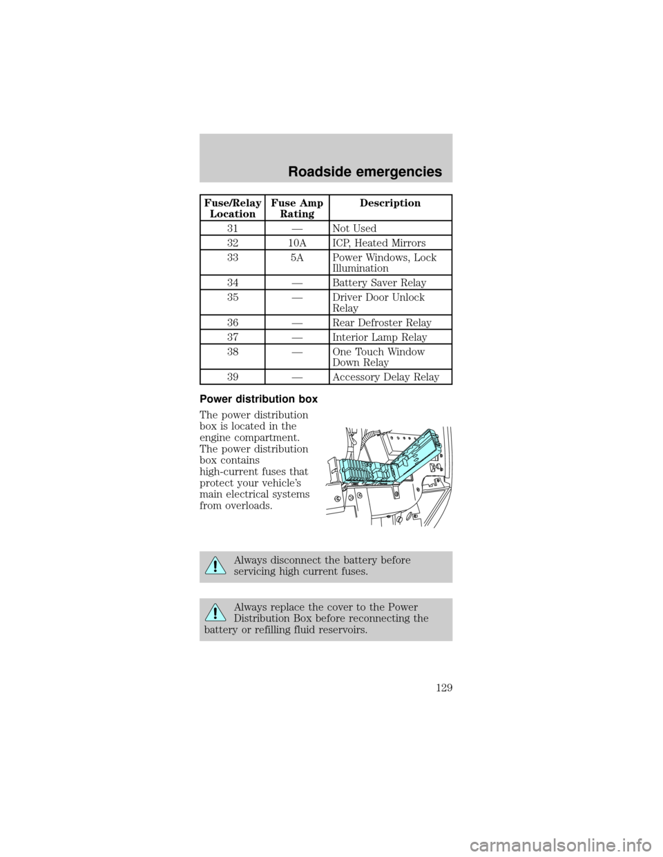
Power distribution box
The power distribution
box is located in the
engine compartment.
The power distribution
box contains
high-current fuses that
protect your vehicle's
main electrical systems
from overloads.
Always disconnect the battery before
servicing high current fuses.
Always replace the cover to the Power
Distribution Box before reconnecting the
battery or refilling fluid reservoirs.
Roadside emergencies
129
Page 130 of 224
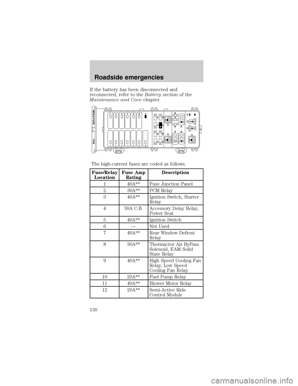
If the battery has been disconnected and
reconnected, refer to theBatterysection of the
Maintenance and Carechapter.
The high-current fuses are coded as follows.
Fuse/Relay
LocationFuse Amp
RatingDescription
1 40A** Fuse Junction Panel
2 30A** PCM Relay
3 40A** Ignition Switch, Starter
Relay
4 30A C.B. Accessory Delay Relay,
Power Seat
5 40A** Ignition Switch
6 Ð Not Used
7 40A** Rear Window Defrost
Relay
8 30A** Thermactor Air ByPass
Solenoid, EAM Solid
State Relay
9 40A** High Speed Cooling Fan
Relay, Low Speed
Cooling Fan Relay
10 20A** Fuel Pump Relay
11 40A** Blower Motor Relay
12 20A** Semi-Active Ride
Control Module
22
14 13
12 11
10 9
87
175A MEGA-FUSE
65
43
2121 24 23 28 27 26 2530 2931
33 3432
20 19
18 17 16 15
Roadside emergencies
130