brake FORD TAURUS 2005 4.G Owners Manual
[x] Cancel search | Manufacturer: FORD, Model Year: 2005, Model line: TAURUS, Model: FORD TAURUS 2005 4.GPages: 248, PDF Size: 2.66 MB
Page 2 of 248
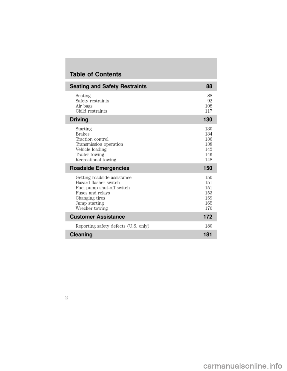
Seating and Safety Restraints 88
Seating 88
Safety restraints 92
Air bags 108
Child restraints 117
Driving 130
Starting 130
Brakes 134
Traction control 136
Transmission operation 138
Vehicle loading 142
Trailer towing 146
Recreational towing 148
Roadside Emergencies 150
Getting roadside assistance 150
Hazard flasher switch 151
Fuel pump shut-off switch 151
Fuses and relays 153
Changing tires 159
Jump starting 165
Wrecker towing 170
Customer Assistance 172
Reporting safety defects (U.S. only) 180
Cleaning 181
Table of Contents
2
Page 6 of 248

SPECIAL NOTICES
Emission warranty
The New Vehicle Limited Warranty includes Bumper-to-Bumper
Coverage, Safety Restraint Coverage, Corrosion Coverage, and 6.0L
Power Stroke Diesel Engine Coverage. In addition, your vehicle is eligible
for Emissions Defect and Emissions Performance Warranties. For a
detailed description of what is covered and what is not covered, refer to
theWarranty Guidethat is provided to you along with your Owner's
Guide.
Service Data Recording
Service data recorders in your vehicle are capable of collecting and
storing diagnostic information about your vehicle. This potentially
includes information about the performance or status of various systems
and modules in the vehicle, such as engine, throttle, steering or brake
systems. In order to properly diagnose and service your vehicle, Ford
Motor Company, Ford of Canada, and service and repair facilities may
access vehicle diagnostic information through a direct connection to your
vehicle when diagnosing or servicing your vehicle.
Event Data Recording
Other modules in your vehicle Ð event data recorders Ð are capable of
collecting and storing data during a crash or near crash event. The
recorded information may assist in the investigation of such an event.
The modules may record information about both the vehicle and the
occupants, potentially including information such as:
²how various systems in your vehicle were operating;
²whether or not the driver and passenger seatbelts were buckled;
²how far (if at all) the driver was depressing the accelerator and/or the
brake pedal;
²how fast the vehicle was traveling; and
²where the driver was positioning the steering wheel.
To access this information, special equipment must be directly connected
to the recording modules. Ford Motor Company and Ford of Canada do
not access event data recorder information without obtaining consent,
unless pursuant to court order or where required by law enforcement,
other government authorities or other third parties acting with lawful
authority. Other parties may seek to access the information
independently of Ford Motor Company and Ford of Canada.
Introduction
6
Page 8 of 248
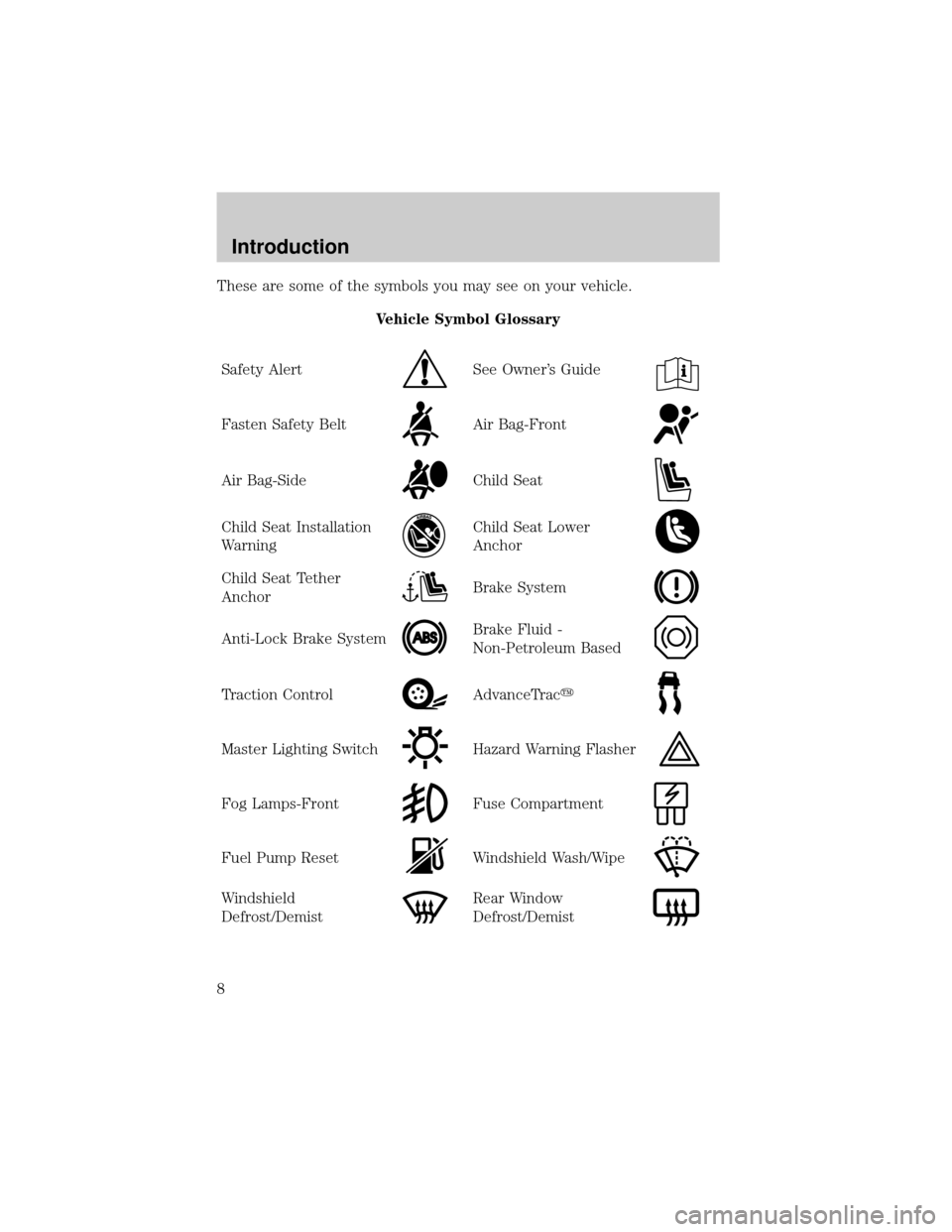
These are some of the symbols you may see on your vehicle.
Vehicle Symbol Glossary
Safety Alert
See Owner's Guide
Fasten Safety BeltAir Bag-Front
Air Bag-SideChild Seat
Child Seat Installation
WarningChild Seat Lower
Anchor
Child Seat Tether
AnchorBrake System
Anti-Lock Brake SystemBrake Fluid -
Non-Petroleum Based
Traction ControlAdvanceTracy
Master Lighting SwitchHazard Warning Flasher
Fog Lamps-FrontFuse Compartment
Fuel Pump ResetWindshield Wash/Wipe
Windshield
Defrost/DemistRear Window
Defrost/Demist
Introduction
8
Page 11 of 248
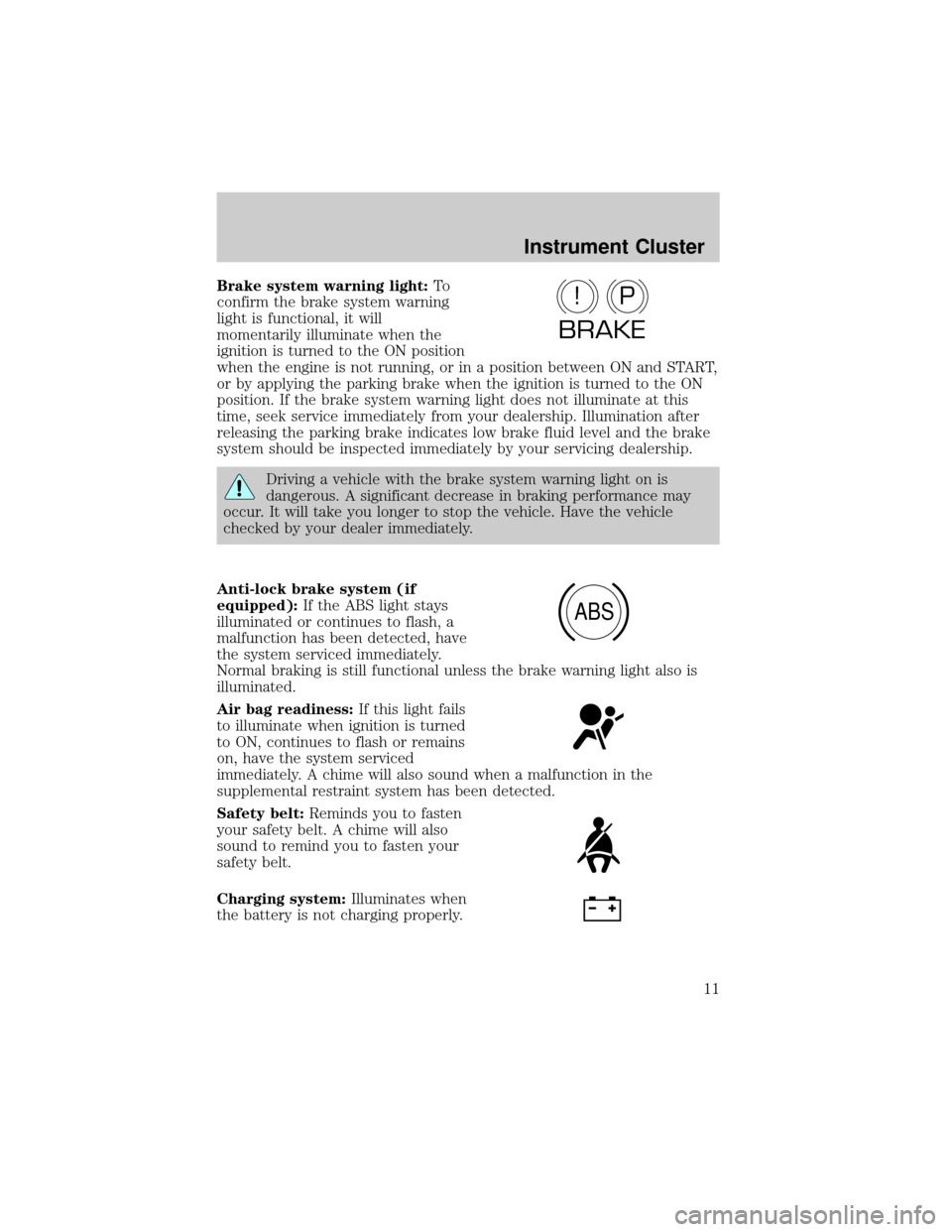
Brake system warning light:To
confirm the brake system warning
light is functional, it will
momentarily illuminate when the
ignition is turned to the ON position
when the engine is not running, or in a position between ON and START,
or by applying the parking brake when the ignition is turned to the ON
position. If the brake system warning light does not illuminate at this
time, seek service immediately from your dealership. Illumination after
releasing the parking brake indicates low brake fluid level and the brake
system should be inspected immediately by your servicing dealership.
Driving a vehicle with the brake system warning light on is
dangerous. A significant decrease in braking performance may
occur. It will take you longer to stop the vehicle. Have the vehicle
checked by your dealer immediately.
Anti-lock brake system (if
equipped):If the ABS light stays
illuminated or continues to flash, a
malfunction has been detected, have
the system serviced immediately.
Normal braking is still functional unless the brake warning light also is
illuminated.
Air bag readiness:If this light fails
to illuminate when ignition is turned
to ON, continues to flash or remains
on, have the system serviced
immediately. A chime will also sound when a malfunction in the
supplemental restraint system has been detected.
Safety belt:Reminds you to fasten
your safety belt. A chime will also
sound to remind you to fasten your
safety belt.
Charging system:Illuminates when
the battery is not charging properly.
P!
BRAKE
ABS
Instrument Cluster
11
Page 30 of 248
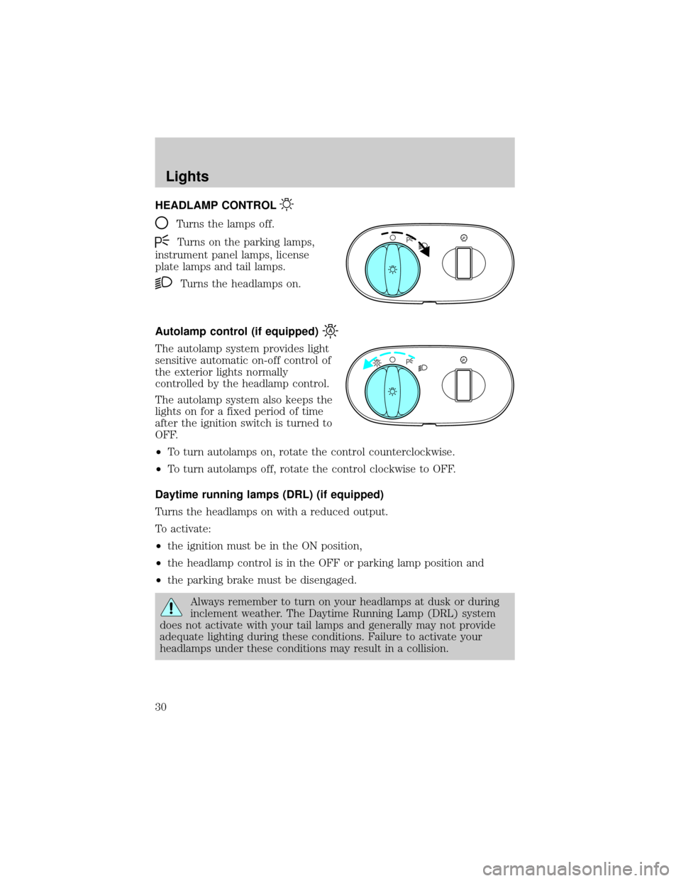
HEADLAMP CONTROL
Turns the lamps off.
Turns on the parking lamps,
instrument panel lamps, license
plate lamps and tail lamps.
Turns the headlamps on.
Autolamp control (if equipped)
The autolamp system provides light
sensitive automatic on-off control of
the exterior lights normally
controlled by the headlamp control.
The autolamp system also keeps the
lights on for a fixed period of time
after the ignition switch is turned to
OFF.
²To turn autolamps on, rotate the control counterclockwise.
²To turn autolamps off, rotate the control clockwise to OFF.
Daytime running lamps (DRL) (if equipped)
Turns the headlamps on with a reduced output.
To activate:
²the ignition must be in the ON position,
²the headlamp control is in the OFF or parking lamp position and
²the parking brake must be disengaged.
Always remember to turn on your headlamps at dusk or during
inclement weather. The Daytime Running Lamp (DRL) system
does not activate with your tail lamps and generally may not provide
adequate lighting during these conditions. Failure to activate your
headlamps under these conditions may result in a collision.
A
Lights
Lights
30
Page 35 of 248
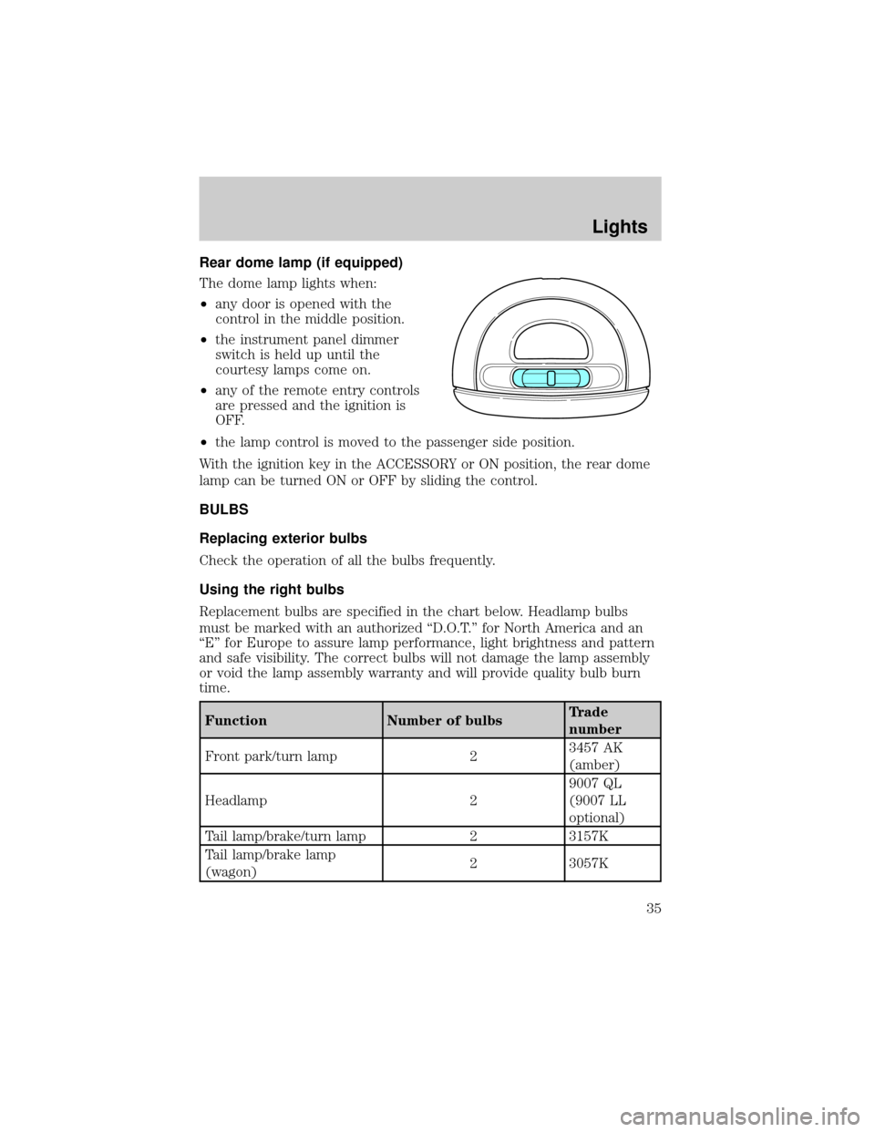
Rear dome lamp (if equipped)
The dome lamp lights when:
²any door is opened with the
control in the middle position.
²the instrument panel dimmer
switch is held up until the
courtesy lamps come on.
²any of the remote entry controls
are pressed and the ignition is
OFF.
²the lamp control is moved to the passenger side position.
With the ignition key in the ACCESSORY or ON position, the rear dome
lamp can be turned ON or OFF by sliding the control.
BULBS
Replacing exterior bulbs
Check the operation of all the bulbs frequently.
Using the right bulbs
Replacement bulbs are specified in the chart below. Headlamp bulbs
must be marked with an authorized ªD.O.T.º for North America and an
ªEº for Europe to assure lamp performance, light brightness and pattern
and safe visibility. The correct bulbs will not damage the lamp assembly
or void the lamp assembly warranty and will provide quality bulb burn
time.
Function Number of bulbsTrade
number
Front park/turn lamp 23457 AK
(amber)
Headlamp 29007 QL
(9007 LL
optional)
Tail lamp/brake/turn lamp 2 3157K
Tail lamp/brake lamp
(wagon)2 3057K
Lights
35
Page 36 of 248
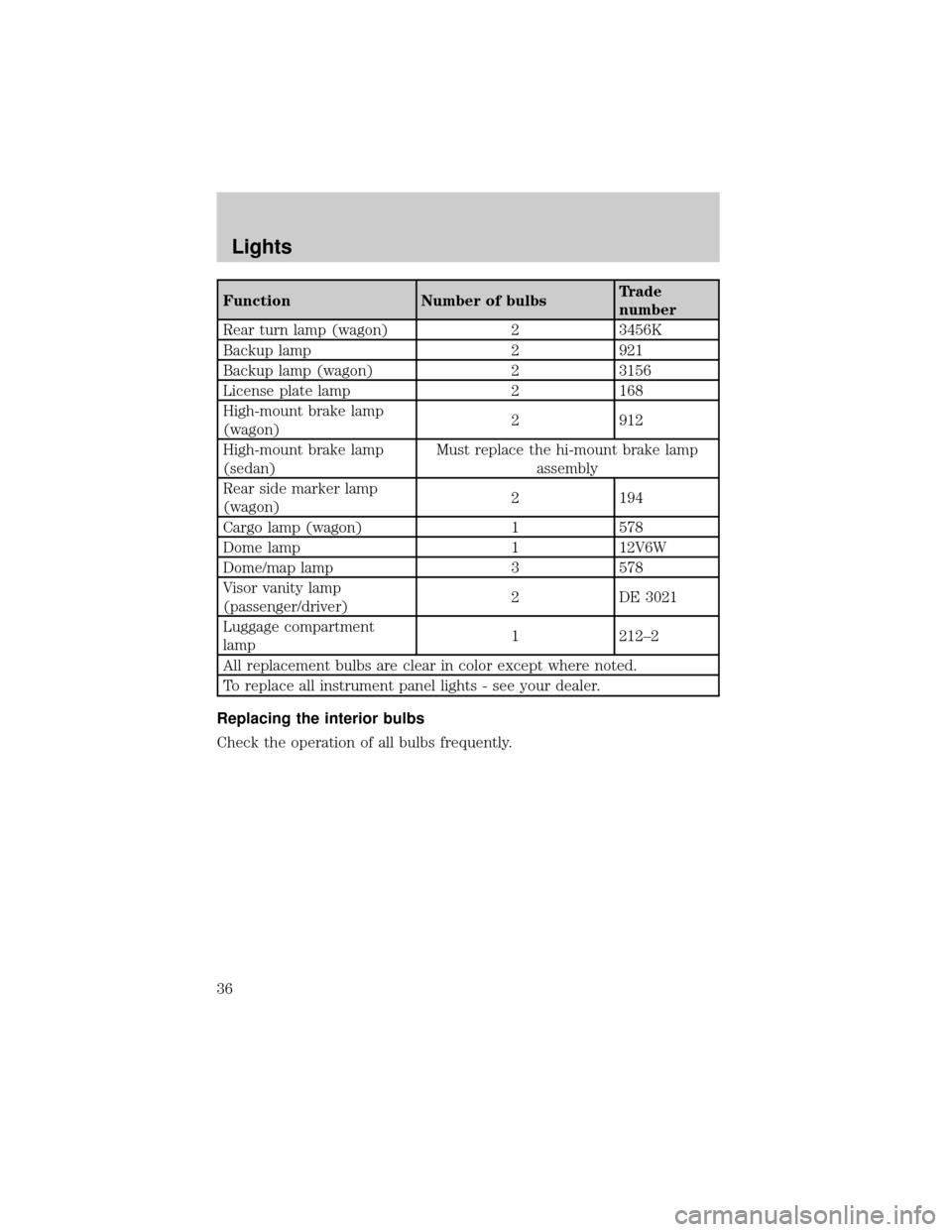
Function Number of bulbsTrade
number
Rear turn lamp (wagon) 2 3456K
Backup lamp 2 921
Backup lamp (wagon) 2 3156
License plate lamp 2 168
High-mount brake lamp
(wagon)2 912
High-mount brake lamp
(sedan)Must replace the hi-mount brake lamp
assembly
Rear side marker lamp
(wagon)2 194
Cargo lamp (wagon) 1 578
Dome lamp 1 12V6W
Dome/map lamp 3 578
Visor vanity lamp
(passenger/driver)2 DE 3021
Luggage compartment
lamp1 212±2
All replacement bulbs are clear in color except where noted.
To replace all instrument panel lights - see your dealer.
Replacing the interior bulbs
Check the operation of all bulbs frequently.
Lights
36
Page 40 of 248
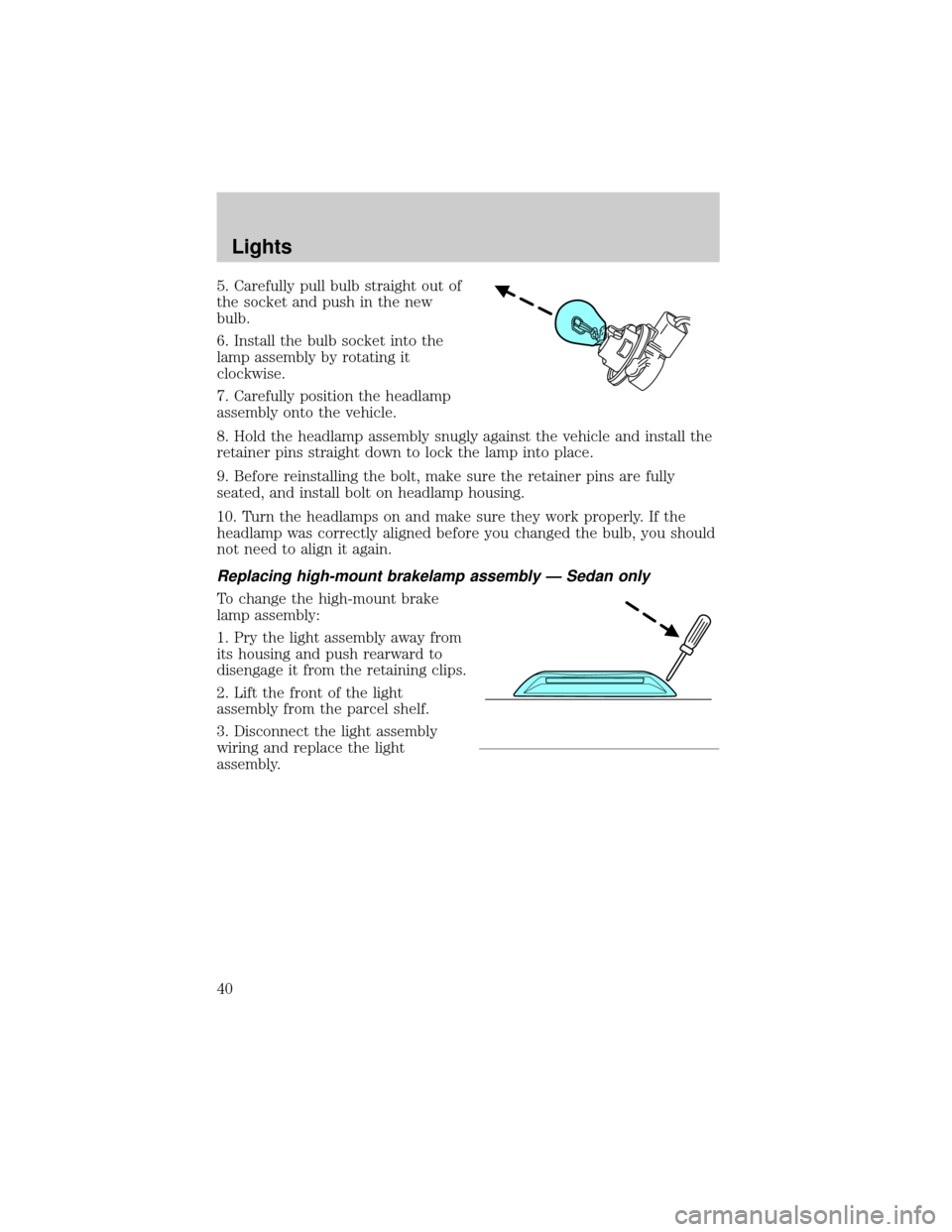
5. Carefully pull bulb straight out of
the socket and push in the new
bulb.
6. Install the bulb socket into the
lamp assembly by rotating it
clockwise.
7. Carefully position the headlamp
assembly onto the vehicle.
8. Hold the headlamp assembly snugly against the vehicle and install the
retainer pins straight down to lock the lamp into place.
9. Before reinstalling the bolt, make sure the retainer pins are fully
seated, and install bolt on headlamp housing.
10. Turn the headlamps on and make sure they work properly. If the
headlamp was correctly aligned before you changed the bulb, you should
not need to align it again.
Replacing high-mount brakelamp assembly Ð Sedan only
To change the high-mount brake
lamp assembly:
1. Pry the light assembly away from
its housing and push rearward to
disengage it from the retaining clips.
2. Lift the front of the light
assembly from the parcel shelf.
3. Disconnect the light assembly
wiring and replace the light
assembly.
Lights
40
Page 41 of 248
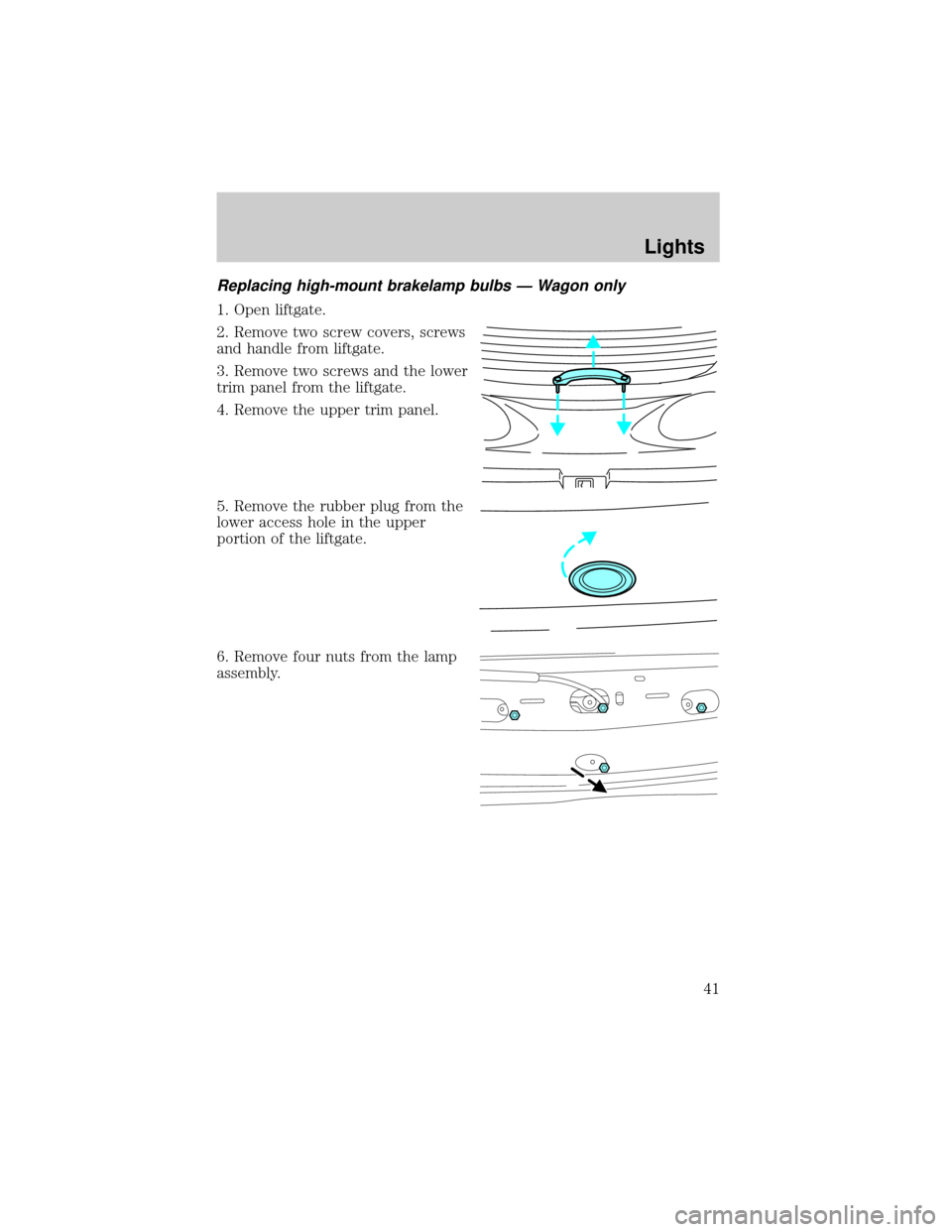
Replacing high-mount brakelamp bulbs Ð Wagon only
1. Open liftgate.
2. Remove two screw covers, screws
and handle from liftgate.
3. Remove two screws and the lower
trim panel from the liftgate.
4. Remove the upper trim panel.
5. Remove the rubber plug from the
lower access hole in the upper
portion of the liftgate.
6. Remove four nuts from the lamp
assembly.
Lights
41
Page 42 of 248
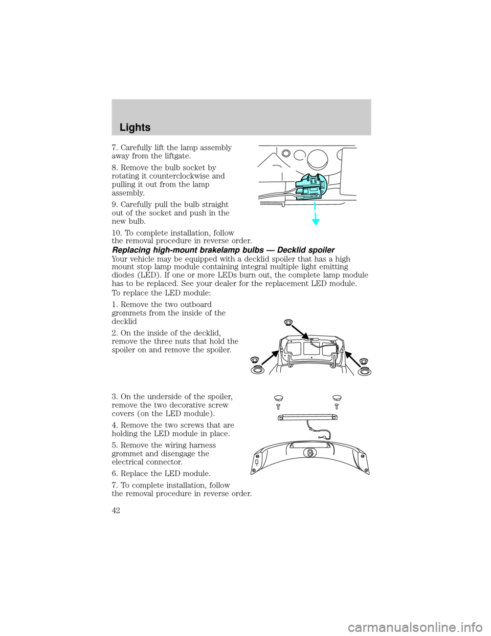
7. Carefully lift the lamp assembly
away from the liftgate.
8. Remove the bulb socket by
rotating it counterclockwise and
pulling it out from the lamp
assembly.
9. Carefully pull the bulb straight
out of the socket and push in the
new bulb.
10. To complete installation, follow
the removal procedure in reverse order.
Replacing high-mount brakelamp bulbs Ð Decklid spoiler
Your vehicle may be equipped with a decklid spoiler that has a high
mount stop lamp module containing integral multiple light emitting
diodes (LED). If one or more LEDs burn out, the complete lamp module
has to be replaced. See your dealer for the replacement LED module.
To replace the LED module:
1. Remove the two outboard
grommets from the inside of the
decklid
2. On the inside of the decklid,
remove the three nuts that hold the
spoiler on and remove the spoiler.
3. On the underside of the spoiler,
remove the two decorative screw
covers (on the LED module).
4. Remove the two screws that are
holding the LED module in place.
5. Remove the wiring harness
grommet and disengage the
electrical connector.
6. Replace the LED module.
7. To complete installation, follow
the removal procedure in reverse order.
Lights
42