ESP FORD TRANSIT 2006 7.G Body And Equipment Mounting Section Manual
[x] Cancel search | Manufacturer: FORD, Model Year: 2006, Model line: TRANSIT, Model: FORD TRANSIT 2006 7.GPages: 234, PDF Size: 33.19 MB
Page 134 of 234
Where wires are required to be extended, break
in points should only be at existing connector
points and only Ford approved connectors should
be used.
Ford approved link harnesses should be used.
Unused Connectors
The harnesses may have a number of unused
connectors – these are dedicated to other
features and options, e.g. heated seats, but are
not always present depending on level of
harness fitted. Ford do not recommend the use
of these connectors for any other purpose than
that intended by design.
Power Outlet / Cigar Lighter
Both features adopt a 20A fusing strategy. With
a single battery system, continued loading of
these features will lead to battery drain, and risk
vehicle starting. If continuous power is required,
a second battery option should be installed and
the customer connection points, where fitted,
utilized.
4.14.4 Installation and Routing Guides
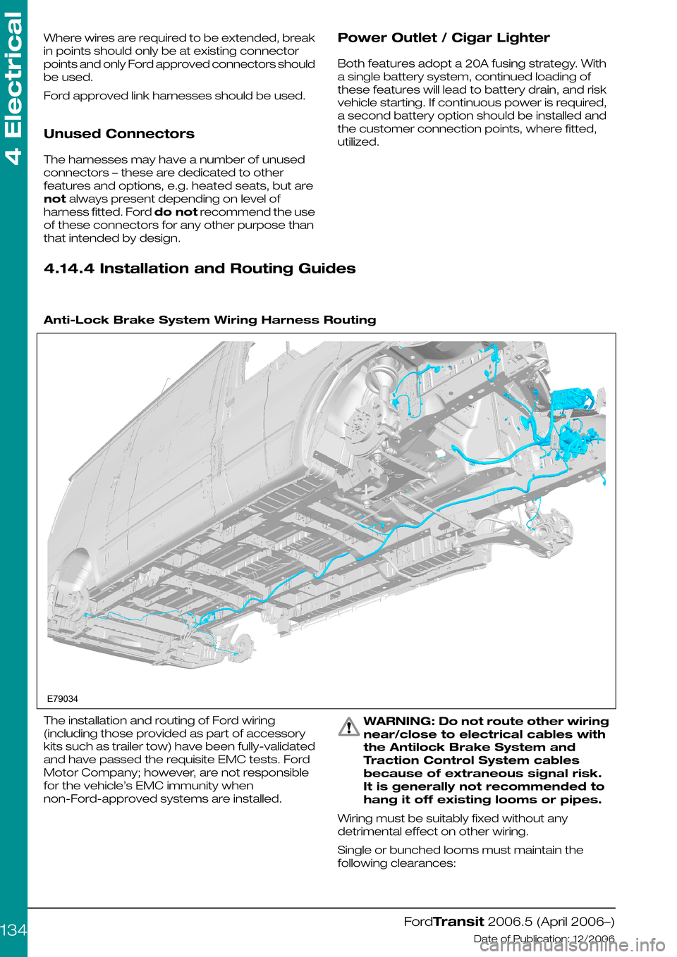
Anti-Lock Brake System Wiring Harness Routing
The installation and routing of Ford wiring
(including those provided as part of accessory
kits such as trailer tow) have been fully-validated
and have passed the requisite EMC tests. Ford
Motor Company; however, are not responsible
for the vehicle’s EMC immunity when
non-Ford-approved systems are installed.
WARNING: Do not route other wiring
near/close to electrical cables with
the Antilock Brake System and
Traction Control System cables
because of extraneous signal risk.
It is generally not recommended to
hang it off existing looms or pipes.
Wiring must be suitably fixed without any
detrimental effect on other wiring.
Single or bunched looms must maintain the
following clearances:
FordTransit 2006.5 (April 2006–)
Date of Publication: 12/2006
4 Electrical
134E79034
Page 137 of 234
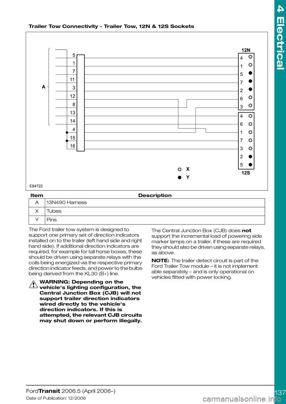
Trailer Tow Connectivity - Trailer Tow, 12N & 12S Sockets
DescriptionItem
13N490 HarnessA
TubesX
PinsY
The Ford trailer tow system is designed to
support one primary set of direction indicators
installed on to the trailer (left hand side and right
hand side). If additional direction indicators are
required, for example for tall horse boxes, these
should be driven using separate relays with the
coils being energized via the respective primary
direction indicator feeds, and power to the bulbs
being derived from the KL30 (B+) line.
WARNING: Depending on the
vehicle's lighting configuration, the
Central Junction Box (CJB) will not
support trailer direction indicators
wired directly to the vehicle's
direction indicators. If this is
attempted, the relevant CJB circuits
may shut down or perform illegally.
The Central Junction Box (CJB) does not
support the incremental load of powering side
marker lamps on a trailer, if these are required
they should also be driven using separate relays,
as above.
NOTE: The trailer detect circuit is part of the
Ford Trailer Tow module – it is not implement
able separately – and is only operational on
vehicles fitted with power locking.
FordTransit 2006.5 (April 2006–)
Date of Publication: 12/2006
4 Electrical
137E8472241572634617325517113128131441516
Page 140 of 234
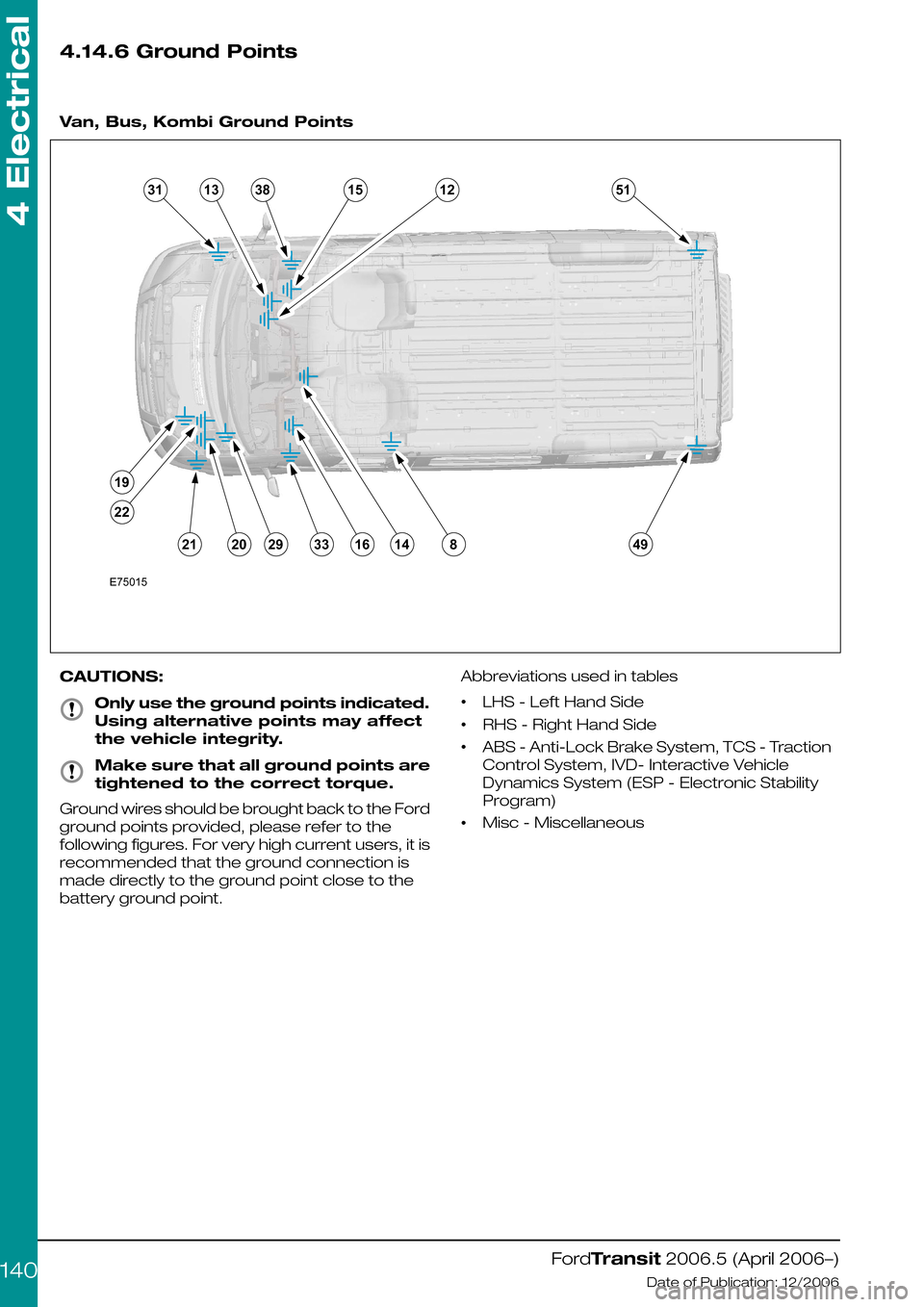
4.14.6 Ground Points
Van, Bus, Kombi Ground Points
CAUTIONS:
Only use the ground points indicated.
Using alternative points may affect
the vehicle integrity.
Make sure that all ground points are
tightened to the correct torque.
Ground wires should be brought back to the Ford
ground points provided, please refer to the
following figures. For very high current users, it is
recommended that the ground connection is
made directly to the ground point close to the
battery ground point.
Abbreviations used in tables
•LHS - Left Hand Side
•RHS - Right Hand Side
•ABS - Anti-Lock Brake System, TCS - Traction
Control System, IVD- Interactive Vehicle
Dynamics System (ESP - Electronic Stability
Program)
•Misc - Miscellaneous
FordTransit 2006.5 (April 2006–)
Date of Publication: 12/2006
4 Electrical
140E750153113381512518491416332920211922
Page 141 of 234
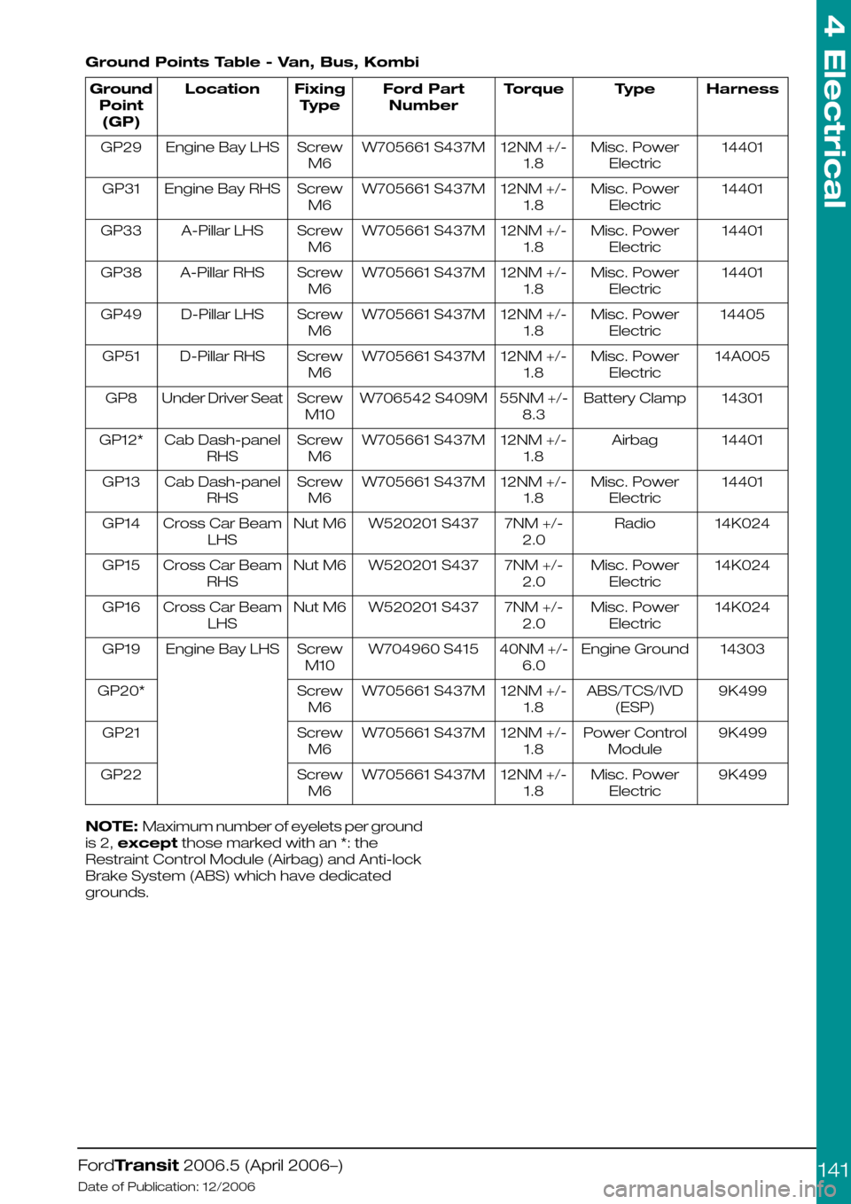
Ground Points Table - Van, Bus, Kombi
HarnessTypeTorqueFord Part
Number
Fixing
Type
LocationGround
Point
(GP)
14401Misc. Power
Electric
12NM +/-
1.8
W705661 S437MScrew
M6
Engine Bay LHSGP29
14401Misc. Power
Electric
12NM +/-
1.8
W705661 S437MScrew
M6
Engine Bay RHSGP31
14401Misc. Power
Electric
12NM +/-
1.8
W705661 S437MScrew
M6
A-Pillar LHSGP33
14401Misc. Power
Electric
12NM +/-
1.8
W705661 S437MScrew
M6
A-Pillar RHSGP38
14405Misc. Power
Electric
12NM +/-
1.8
W705661 S437MScrew
M6
D-Pillar LHSGP49
14A005Misc. Power
Electric
12NM +/-
1.8
W705661 S437MScrew
M6
D-Pillar RHSGP51
14301Battery Clamp55NM +/-
8.3
W706542 S409MScrew
M10
Under Driver SeatGP8
14401Airbag12NM +/-
1.8
W705661 S437MScrew
M6
Cab Dash-panel
RHS
GP12*
14401Misc. Power
Electric
12NM +/-
1.8
W705661 S437MScrew
M6
Cab Dash-panel
RHS
GP13
14K024Radio7NM +/-
2.0
W520201 S437Nut M6Cross Car Beam
LHS
GP14
14K024Misc. Power
Electric
7NM +/-
2.0
W520201 S437Nut M6Cross Car Beam
RHS
GP15
14K024Misc. Power
Electric
7NM +/-
2.0
W520201 S437Nut M6Cross Car Beam
LHS
GP16
14303Engine Ground40NM +/-
6.0
W704960 S415Screw
M10
Engine Bay LHSGP19
9K499ABS/TCS/IVD
(ESP)
12NM +/-
1.8
W705661 S437MScrew
M6
GP20*
9K499Power Control
Module
12NM +/-
1.8
W705661 S437MScrew
M6
GP21
9K499Misc. Power
Electric
12NM +/-
1.8
W705661 S437MScrew
M6
GP22
NOTE: Maximum number of eyelets per ground
is 2, except those marked with an *: the
Restraint Control Module (Airbag) and Anti-lock
Brake System (ABS) which have dedicated
grounds.
FordTransit 2006.5 (April 2006–)
Date of Publication: 12/2006
4 Electrical
141
Page 143 of 234
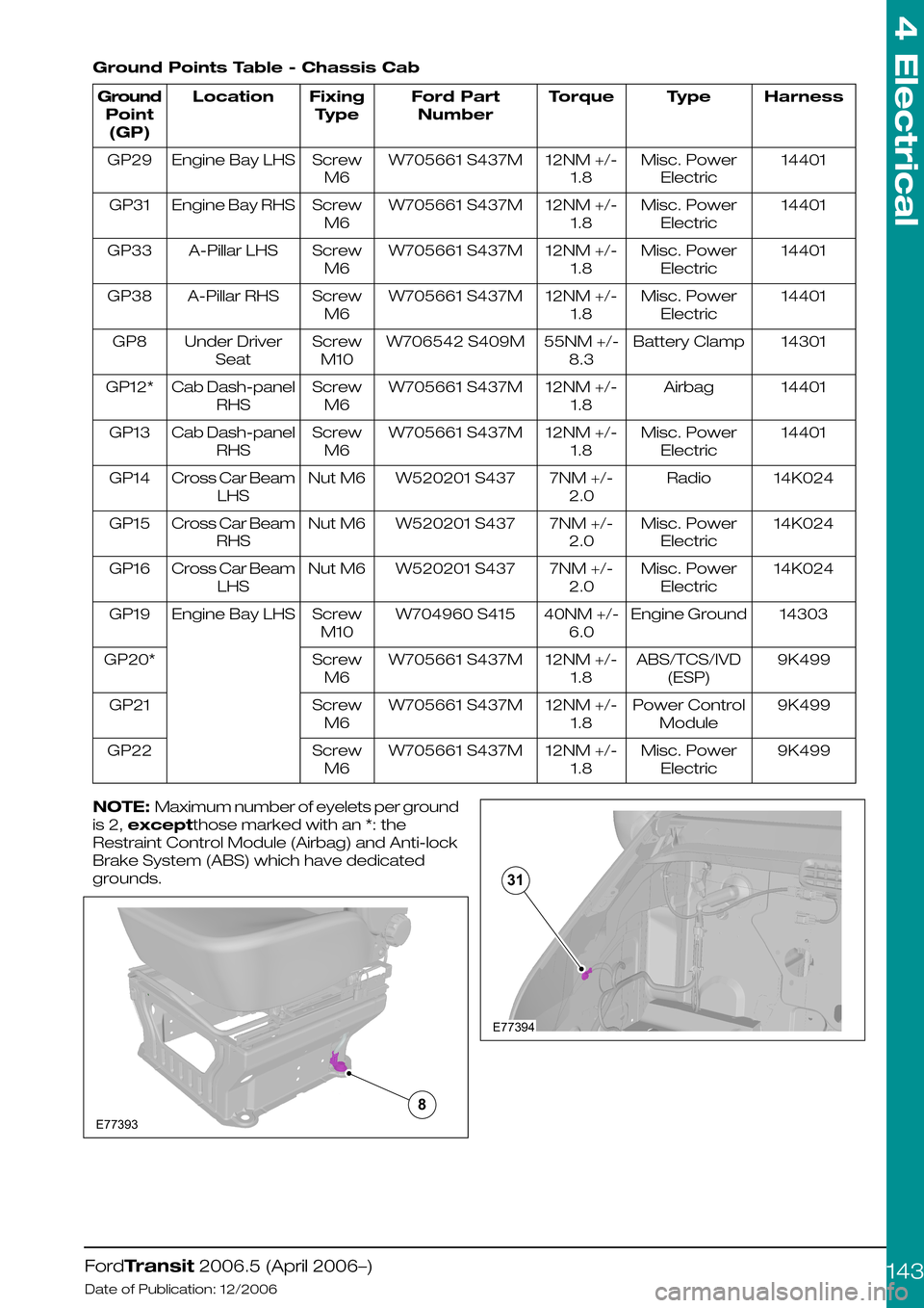
Ground Points Table - Chassis Cab
HarnessTypeTorqueFord Part
Number
Fixing
Type
LocationGround
Point
(GP)
14401Misc. Power
Electric
12NM +/-
1.8
W705661 S437MScrew
M6
Engine Bay LHSGP29
14401Misc. Power
Electric
12NM +/-
1.8
W705661 S437MScrew
M6
Engine Bay RHSGP31
14401Misc. Power
Electric
12NM +/-
1.8
W705661 S437MScrew
M6
A-Pillar LHSGP33
14401Misc. Power
Electric
12NM +/-
1.8
W705661 S437MScrew
M6
A-Pillar RHSGP38
14301Battery Clamp55NM +/-
8.3
W706542 S409MScrew
M10
Under Driver
Seat
GP8
14401Airbag12NM +/-
1.8
W705661 S437MScrew
M6
Cab Dash-panel
RHS
GP12*
14401Misc. Power
Electric
12NM +/-
1.8
W705661 S437MScrew
M6
Cab Dash-panel
RHS
GP13
14K024Radio7NM +/-
2.0
W520201 S437Nut M6Cross Car Beam
LHS
GP14
14K024Misc. Power
Electric
7NM +/-
2.0
W520201 S437Nut M6Cross Car Beam
RHS
GP15
14K024Misc. Power
Electric
7NM +/-
2.0
W520201 S437Nut M6Cross Car Beam
LHS
GP16
14303Engine Ground40NM +/-
6.0
W704960 S415Screw
M10
Engine Bay LHSGP19
9K499ABS/TCS/IVD
(ESP)
12NM +/-
1.8
W705661 S437MScrew
M6
GP20*
9K499Power Control
Module
12NM +/-
1.8
W705661 S437MScrew
M6
GP21
9K499Misc. Power
Electric
12NM +/-
1.8
W705661 S437MScrew
M6
GP22
NOTE: Maximum number of eyelets per ground
is 2, exceptthose marked with an *: the
Restraint Control Module (Airbag) and Anti-lock
Brake System (ABS) which have dedicated
grounds.
FordTransit 2006.5 (April 2006–)
Date of Publication: 12/2006
4 Electrical
143E773938 E7739431
Page 154 of 234
harness that provides roof-mounted rear turn
indicators, powered via relays. This should be
used in conjunction with SVO fusebox.
3.Chassis cab LED rear lamp cluster
replacement recommendations, especially
turn indicator relay implications – see lighting
load table. Generally the use of LED equivalent
lighting systems reduces the electrical load on
the vehicle; however, special care needs to
be taken with respect to any change to or
addition of turn indicator lights. Depending on
the current requirements of the LED(s)
compared to the bulb it is replacing, a ballast
resistor may be required, if not already
integrated into the LED lamp assembly.
Without this, bulb outage detection for turn
indicators will be affected, which is a legal
requirement.
Additional turn indicators must be powered
through relays (max 300mA), driven by existing
turn lights. The maximum load that the Central
Junction Box can drive is 3 x 21W per side (front,
rear and CAT 6 turn indicators); but even if the
vehicle is not fitted with the CAT 6 lights, the feeds
for these should not be used as the Central
Junction Box would need reconfiguring, which
could have safety as well as functional
implications.
4.Special Vehicle Option beacon switch: wiring
locations, circuit diagrams and max amperage
– see Special Vehicle Option fuse box
schematic (max current is 15A); there is
provision for the Special Vehicle Option beacon
switch in an empty switch location on the
instrument panel.
5.Rear loom connector detail location and supply
details for retro-fit loom extension for
example:- when extending a medium wheel
base, long wheel base or extended frame
overhang, what connectors do they use to
make a plug and play loom extension? – for
chassis cab vehicles, there is an Special
Vehicle Option extension loom for rear lamps
(part number 6C1V-14408-A*). There is not, at
present, a similar loom for Van, Bus and
Kombi's, although the appropriate mating
connector is now tooled, so this would be
possible.
Miscellaneous Systems
Handbrake on - Cluster Warning Light -
Unless the vehicle is specified with options that
drive the handbrake warning light (for example
ESP, Australia market), the components making
up this system are not fitted. We do not
recommend installation of this feature as an
aftermarket addition. There are several reasons
for this:
1.Not all circuits carry the requisite wire as a give
away:
•The wires might be part of the main vehicle
harness (14401) even if not used – for example
camper vehicles are normally ordered with
power mirrors, and the wires will be present
as a give-away.
•The seat pedestal harness (14K076), however,
is vehicle specific – if the handbrake is not part
of the specification, it will not be present or
give-away. This harness would need to be
changed to the compatible part that also
includes the handbrake warning light circuit.
2.The handbrake switch (part number
2F2T-15852-A*) together with its short jumper
harness (6C1T-15K857-A*) would need to be
obtained and fitted.
3.The handbrake warning light is in all clusters,
but unless the vehicle config. parameter
“parking brake switch” is set, the Central
Junction Box will not read this input, and hence
NO CAN message sent to the cluster.
Reconfiguration can only be done at a Ford
Dealer.
NOTE: If a vehicle already has a handbrake
warning light in the cluster, or one is installed as
per the Ford design, it is not possible to utilize the
wire from the handbrake switch as part of an
interlock circuit (this is a pull up resistor input that
provides a wetting current of 20mA – anything in
excess of this, for example through additional
circuitry, will almost certainly damage the Central
Junction Box). If there is no handbrake switch
installed, it would be possible to add one and
utilize this as part of a separate circuit, up to a
maximum current of 500mA through the switch.
Reverse Sensors (Rear Park Aid
Module)- The factory-fit option is a CAN-based
system, but for Van, Bus, and Kombi vehicles
only. Stand-alone systems can be installed (for
example for chassis cab conversions), but would
need to utilize the PTA line of the radio if muting
is required.
Fuel Fired Heater (FFH)- Add FFH: wiring is
only present (give-away) in certain harnesses.
There was an aftermarket kit available for this
system on current Transit, which could probably
be “updated” to suit V347/8.
Fuel Fired Heater (FFH) - Programmable
FFH: this utilizes a timer/control module mounted
to the Instrument Panel, which necessitates
having the correct Instrument Panel harness
fitted. Retrofit of this would be a difficult.
For both systems, the appropriate 6C1T-14K132
harness would be required (suffix -A* for
Programmable FFH, and suffix –B* for Add FFH).
Central Locking
Locking is controlled by the Central Junction Box
module. There is current sensing on certain
locking circuit pins as part of the security system
– if these are tampered with, locking cannot be
guaranteed.
FordTransit 2006.5 (April 2006–)
Date of Publication: 12/2006
4 Electrical
154
Page 160 of 234
Resistance Ladder
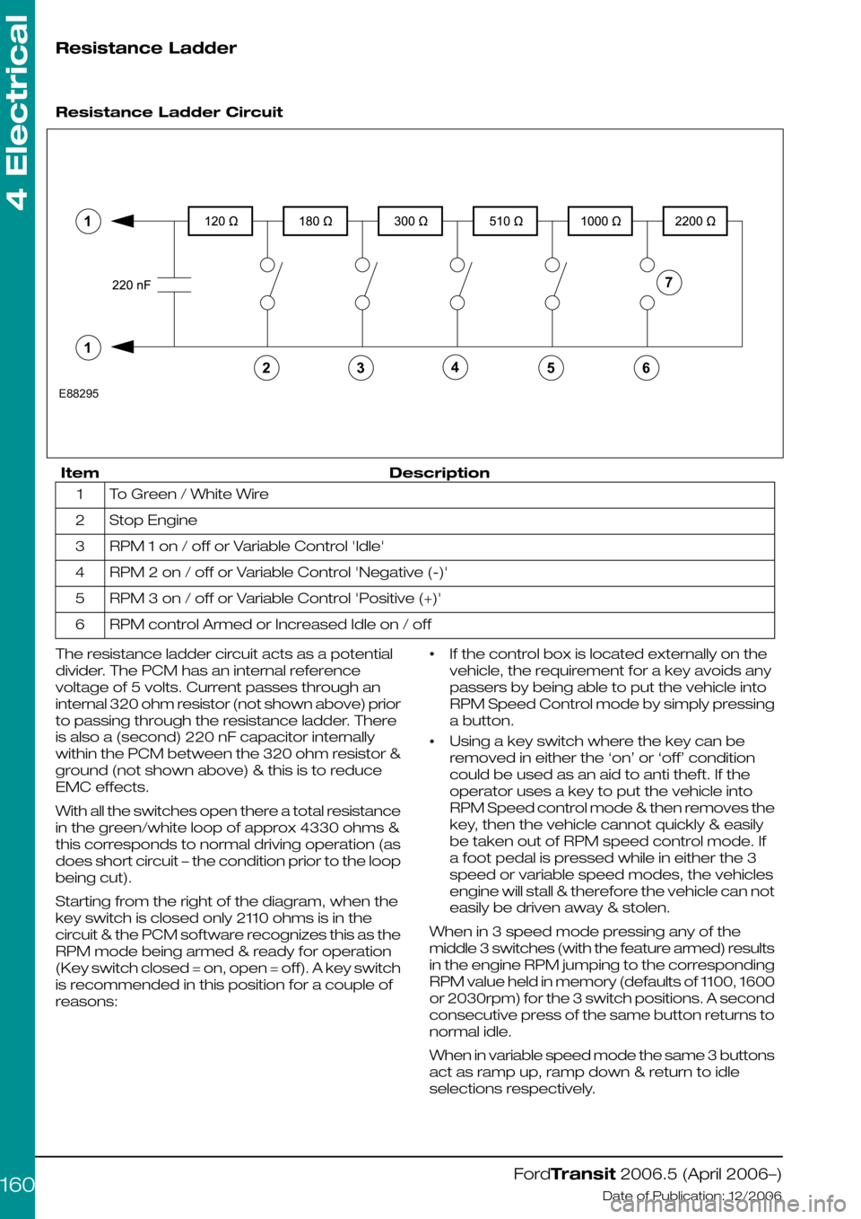
Resistance Ladder Circuit
DescriptionItem
To Green / White Wire1
Stop Engine2
RPM 1 on / off or Variable Control 'Idle'3
RPM 2 on / off or Variable Control 'Negative (-)'4
RPM 3 on / off or Variable Control 'Positive (+)'5
RPM control Armed or Increased Idle on / off6
The resistance ladder circuit acts as a potential
divider. The PCM has an internal reference
voltage of 5 volts. Current passes through an
internal 320 ohm resistor (not shown above) prior
to passing through the resistance ladder. There
is also a (second) 220 nF capacitor internally
within the PCM between the 320 ohm resistor &
ground (not shown above) & this is to reduce
EMC effects.
With all the switches open there a total resistance
in the green/white loop of approx 4330 ohms &
this corresponds to normal driving operation (as
does short circuit – the condition prior to the loop
being cut).
Starting from the right of the diagram, when the
key switch is closed only 2110 ohms is in the
circuit & the PCM software recognizes this as the
RPM mode being armed & ready for operation
(Key switch closed = on, open = off). A key switch
is recommended in this position for a couple of
reasons:
•If the control box is located externally on the
vehicle, the requirement for a key avoids any
passers by being able to put the vehicle into
RPM Speed Control mode by simply pressing
a button.
•Using a key switch where the key can be
removed in either the ‘on’ or ‘off’ condition
could be used as an aid to anti theft. If the
operator uses a key to put the vehicle into
RPM Speed control mode & then removes the
key, then the vehicle cannot quickly & easily
be taken out of RPM speed control mode. If
a foot pedal is pressed while in either the 3
speed or variable speed modes, the vehicles
engine will stall & therefore the vehicle can not
easily be driven away & stolen.
When in 3 speed mode pressing any of the
middle 3 switches (with the feature armed) results
in the engine RPM jumping to the corresponding
RPM value held in memory (defaults of 1100, 1600
or 2030rpm) for the 3 switch positions. A second
consecutive press of the same button returns to
normal idle.
When in variable speed mode the same 3 buttons
act as ramp up, ramp down & return to idle
selections respectively.
FordTransit 2006.5 (April 2006–)
Date of Publication: 12/2006
4 Electrical
16065432E88295711
Page 161 of 234
The software in the PCM responds to the change
of state, so it is recommended that these 3
middle switches be non-latching push button
micro switches. When going from idle to an
elevated RPM the execution of the command
will occur as the button is released. When going
to idle the execution of the command occurs as
the button is pressed.
The final button (the one on the left in Fig. 4) acts
as an ‘emergency’ vehicle engine stop. It is
recommended that this be a red & oversize
non-latching micro switch button. The execution
of this command will occur as the button is
pressed.
All wiring connecting the PCM to the resistance
ladder control box should be shielded & twisted
(33 twists / m) to reduce EMC effects
All resistors should have a tolerance of +/- 5% or
better
Switch contact, connectors & loom (loom
between the green/white wires & the control
box) total resistance must be no greater than 5
ohm max.
The PCM to resister ladder control switch box
loom should not come within 100mm of any other
harness, especially any carrying heavy loads.
Designs which do not require all the button
switches must still have the complete resistor
network with the switches positioned correctly
within the network.
The resistance ladder is acting as a potential
divider
The 220 nF capacitor is used in the circuit to
reduce EMC effects on the system
A suitable two way quality connector should be
used to connect the control box to the two
green/white wires
How to change the default settings
By default, when the feature is first enabled
(either via factory order or via dealer IDS tools),
it will be set to the 3 speed mode of operation
with preset RPM values of 1100, 1600 & 2030rpm
for the 3 speeds.
There are two methods by which these defaults
can be modified:
1.via the IDS diagnostics system at a Ford dealer
(there may be a charge for this)
2.via an inbuilt vehicle ‘learn mode’
Via the IDS system the mode of operation can
freely be changed between any of the 3 modes
of operation, the feature can even be turn off
(disabled). The 3 default RPM speeds can also
be modified.
Via the vehicle ‘learn mode’ the 3 speed mode
& the variable speed mode can be freely
interchanged, however it is not possible to select
the idle up speed mode via the vehicle learn
mode. The 3 default RPM speeds can also be
modified via ‘learn mode’
It is not possible via either method above, to
change the step value of 25rpm per press or the
250 rpm per sec for a held down button, in the
variable rpm speed mode.
Via IDS The RPM Speed Controller menu is under
the tool box tab, then Powertrain, then service
functions, then PCM. The IDS on screen menus
will guide the dealer through the options & setup.
How to enter vehicle ‘Learn mode’
1.Make sure that the RPM Speed controller
switch box is connected but turned off (not
‘armed’)
2.Start the engine (vehicle out of gear & no foot
pedals being pressed, handbrake on)
3.Wait a couple of seconds for the instrument
panel start up diagnostic lights to extinguish
4.Press & release the clutch pedal
5.Press & release the brake pedal
6.Repeat steps 4) & 5) a further four times
(clutch & brake pressed a total of five times
sequentially each)
NOTE: Steps 4) to 6) have to be started within
10 seconds of the engine start
The vehicle should now be in ‘learn mode’
How to Select between modes
1.Enter ‘learn mode’ (see directions above)
2.Arm the RPM speed controller (turn the key
switch to ‘on’)
If the vehicle is already in 3 speed mode (the
initial default):
3.Press & release the brake pedal five times
The vehicle should now be in variable speed
mode. The new settings can be saved & learn
mode exited (see below)
Alternatively
4.Press & release the brake pedal once
The vehicle should now be in 3 speed mode.
The new settings can be saved & learn mode
exited (see below)
Using this method it is easy to change between
these two modes of operation for the RPM
speed controller
NOTE: If the engine stalls out at the initial brake
pedal input then the vehicle was not in, or has
dropped out of ‘learn mode’ & you will have to
restart the procedure.
FordTransit 2006.5 (April 2006–)
Date of Publication: 12/2006
4 Electrical
161
Page 162 of 234
How to change the 3 pre-set default
RPM values in the 3 speed mode
1.Enter ‘learn mode’ (see directions above)
2.Arm the RPM speed controller (turn the key
switch to ‘on’)
3.Press & release the brake pedal once
4.Press & release the RPM button that requires
re-programming
5.Use the accelerator pedal to rev the engine to
the new desired RPM speed & hold at this
speed (only speeds between 1200 to 3000
rpm can be selected in 3 speed mode)
6.Press & release the same RPM button to reset
the stored RPM speed to the current engines
RPM
7.Release the accelerator pedal
8.Repeat steps 4) to 7) for the remaining RPM
buttons
The 3 RPM speeds should now be
re-programmed to the new RPM speeds. The
new settings can be saved & learn mode exited
(see below)
NOTE: If the engine RPM responds to the initial
RPM button press, then the vehicle has not
entered ‘learn mode’ correctly & you will have to
restart the procedure. If the engine stalls out at
the brake or accelerator pedal inputs then the
vehicle was not in, or has dropped out of ‘learn
mode’ & you will have to restart the procedure.
How to save new settings & exit
from ‘Learn mode’
1.From within the ‘learn mode’ & with the RPM
Speed Control switch box ‘armed’, press the
clutch pedal repeatedly until the engine stalls.
2.Restart the engine & test the new settings,
repeat above procedures if necessary
NOTE: The engine stalling indicates that the
settings should have been saved & the vehicle
has exited from ‘learn mode’. Learn mode
however is very specific that the exact steps are
taken in the correct order & within certain time
limits otherwise the learn procedure fails & it may
take several attempts to get this order & timing
correct & a successful modification from the
default settings.
Some Reasons why RPM speed
Control operation may stop or fail
The RPM Speed control software monitors
vehicle information during operation in RPM
speed control mode & will drop out of RPM speed
control and / or stall the engine should any
adverse signals be detected. For example:
•If the engine temperature becomes too hot
then RPM speed control will stop in order to
protect the engine.
•If the engine oil light illuminates then RPM
speed control will stop in order to protect the
engine
•If the low fuel level light illuminates then RPM
speed control will stop so that the vehicle can
be driven to a refueling point.
•If the vehicle speed exceeds approx 2.5 mph
wile in 3 speed or variable speed modes, then
RPM speed control may stop. RPM speed
control should normally be operated with the
hand brake on, but some uses may require a
low level of vehicle ‘creep’ during RPM speed
control operation. Note that there is no sensing
of the park brake on this version of RPM speed
controller to facilitate this type of operation.
•The software monitors for ‘stuck on’ buttons
on the control switch box, this may result in
RPM speed control being halted. A button that
is held down for too long may be registered
by the software as a ‘stuck’ button.
•The software monitors the foot pedals, if
depressed these may stall the engine if in 3
speed mode or variable speed mode (does
not apply to idle up speed)
•If the control switch box circuitry significantly
exceeds 2110 ohms or there is a short circuit
then RPM speed control will not be possible.
•If a PTO conversion has been attempted on a
vehicle with a non ABS braking system then
RPM speed control will fail due to vehicle
speed being registered via a transmission
speed sensor and / or the need to press the
clutch in order to put the vehicle in gear while
in RPM speed control mode.
4.14.10 Adding Connectors,
Terminals and Wiring
Additional Rear Speakers
NOTE: The connectors on the Instrument Panel
harness (14K024) and the main harness (14401)
are reversed between Left Hand Drive (LHD) and
Right Hand Drive (RHD) vehicles, hence different
sets of terminals/wires are required to cover all
the markets.
FordTransit 2006.5 (April 2006–)
Date of Publication: 12/2006
4 Electrical
162
Page 186 of 234
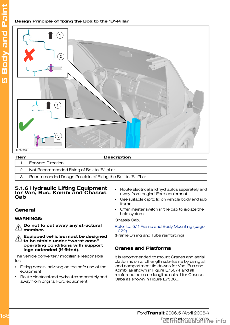
Design Principle of fixing the Box to the 'B'-Pillar
DescriptionItem
Forward Direction1
Not Recommended Fixing of Box to 'B'-pillar2
Recommended Design Principle of Fixing the Box to 'B'-Pillar3
5.1.6 Hydraulic Lifting Equipment
for Van, Bus, Kombi and Chassis
Cab
General
WARNINGS:
Do not to cut away any structural
member.
Equipped vehicles must be designed
to be stable under “worst case”
operating conditions with support
legs extended (if fitted).
The vehicle converter / modifier is responsible
for:
•Fitting decals, advising on the safe use of the
equipment
•Route electrical and hydraulics separately and
away from original Ford equipment
•Route electrical and hydraulics separately and
away from original Ford equipment
•Use suitable clip to fix on vehicle body and sub
frame
•Offer master switch in the cab to isolate the
hole system
Chassis Cab.
Refer to: 5.11 Frame and Body Mounting (page
222).
(Frame Drilling and Tube reinforcing)
Cranes and Platforms
It is recommended to mount Cranes and aerial
platforms on a full length sub-frame by using all
load compartment tie downs for Van, Bus and
Kombi as shown in Figure E75874 and all
reinforced holes on longitudinal rail for Chassis
Cabs as shown in Figure E75880.
FordTransit 2006.5 (April 2006–)
Date of Publication: 12/2006
5 Body and Paint
1861123E74864