ESP FORD TRANSIT 2006 7.G Body And Equipment Mounting Section Manual
[x] Cancel search | Manufacturer: FORD, Model Year: 2006, Model line: TRANSIT, Model: FORD TRANSIT 2006 7.GPages: 234, PDF Size: 33.19 MB
Page 192 of 234
For Chassis Cab with tail lift design as described
above it is recommended to use unique body
sub-frame for fixing to Chassis Cab structure. For
connection between sub-frame Chassis Cab
body structure please refer to Figure E74696.
For Chassis Cab with under-slung tail lift load
capacity is up to 1000kg at 1000mm from rear
end of chassis frame to center of load if mounted
and functioning on centre line of vehicle. If
mounted and functioning off center line or at the
side of the vehicle load capacity is reduced to
500kg at 1000mm from side/rear end to center
of load.
Greater off-sets and/or loads require additional
stabilizing equipment such as outriggers or
ground jacks. It is recommended not to increase
vehicle body stress over limit as given by load
factors above. If uncertain please consult your
local national sales representative or the Vehicle
Converter Advisory Service [email protected].
It is the Vehicle converters responsibility to fit a
decal to the converted vehicle stating that the
equipment must not be used without
outriggers/ground jacks in operating position. It
is also the vehicle converters responsibility to
guarantee safe functioning of the equipment.
For hydraulic tail lifts as used for general loading
or more specialized for wheel-chair lifts please
refer to Figure E75874.
5.1.7 Partitions (Bulkhead) - Driver
and Front Passenger(s)
Protection on Van, Bus and Kombi
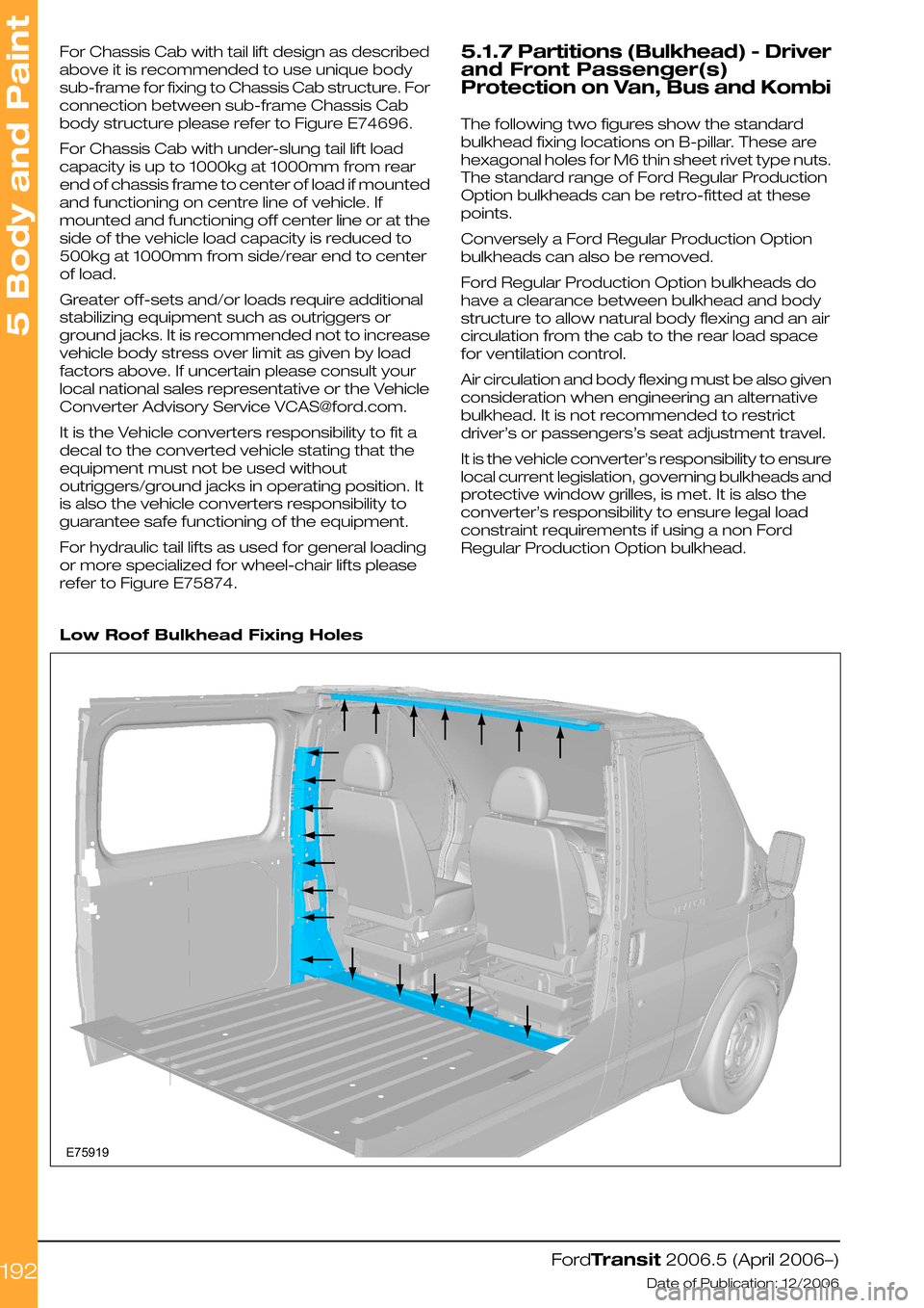
The following two figures show the standard
bulkhead fixing locations on B-pillar. These are
hexagonal holes for M6 thin sheet rivet type nuts.
The standard range of Ford Regular Production
Option bulkheads can be retro-fitted at these
points.
Conversely a Ford Regular Production Option
bulkheads can also be removed.
Ford Regular Production Option bulkheads do
have a clearance between bulkhead and body
structure to allow natural body flexing and an air
circulation from the cab to the rear load space
for ventilation control.
Air circulation and body flexing must be also given
consideration when engineering an alternative
bulkhead. It is not recommended to restrict
driver’s or passengers’s seat adjustment travel.
It is the vehicle converter’s responsibility to ensure
local current legislation, governing bulkheads and
protective window grilles, is met. It is also the
converter’s responsibility to ensure legal load
constraint requirements if using a non Ford
Regular Production Option bulkhead.
Low Roof Bulkhead Fixing Holes
FordTransit 2006.5 (April 2006–)
Date of Publication: 12/2006
5 Body and Paint
192E75919
Page 216 of 234
5.7.5 Roof Racks
Roof racks may be fitted to all van, bus and kombi
variants as illustrated in figure E75917, providing
the following is satisfied:
•The carried load does not exceed 100kg (Body
Builder to ensure owner’s hand book identifies
this limitation).
•The carried load does not exceed 300mm
load height (converter to ensure owner’s
information book identifies this limitation).
•The load is evenly distributed (converter to
ensure owner’s information book identifies this
limitation).
•The rack and subsequent carried load is
supported in the roof drip rails irrespective of
rack retaining method.
•The unit load on the roof drip, under worst
case loading, must not exceed 75kg per rack
foot.
•The rack is clamped to the drip rail at six (6)
points per illustration, or alternatively bolted
through the roof panel with minimum six (6)
M8 bolts, self locking nuts and 3mm X 50mm
square spread plates.
•The rack leading edge preferably should not
be located forward of the rear edge of the
driver’s door, or “B” pillar as shown.
Double Cab
The forgoing limitations are based on ensuring
body structure integrity, vehicle handling, braking
and plated axle weights. Such considerations
must also be applied to any double cab
applications, in particular steering, braking and
front axle plated weight and the extra continuous
loads on the “A” pillar, which should not exceed
60 kg total incremental load.
Ensure that the planned loaded vehicle operates
within its designed Center of Gravity condition.
For details please consult the Vehicle Converter
Advisory Service [email protected].
FordTransit 2006.5 (April 2006–)
Date of Publication: 12/2006
5 Body and Paint
216
Page 226 of 234
5.11.3 Extended Chassis Frame
General:
•Rear overhang extensions are available as
Regular Production Option.
•Bodies or equipment exceeding the standard
extension length must be supported, please
refer to Figure E74575 low body longitudinal
members or Figure E74576 self-supporting
body structures.
•It is the Body Builder's responsibility to mark-up
the owners’ handbook advising the available
payload. Axle plated weights and maximum
allowable axle mass as shown in this manual
must not be exceeded.
•The vehicle should be planned for uniformly
distributed loads.
5.11.4 Non Standard Rear Chassis
Frame Extension
Extensions longer than the standard Regular
Production Option must comply with the following
guidelines:
•The original rear cross member and or
under-run bar or equivalent must be
repositioned at the end of any altered
extension to meet legislation, please refer to
Figure E74578 Non Regular Production Option
rear chassis frame extensions. Also see.
Refer to: 1.17 Towing (page 54).
(Figure E74854)
•The standard fit under-run bar is bolted on as
shown in Figure E74578 and Figure E74854
as mentioned in previous paragraph.
•The altered extension assembly must include
a cross member adjacent to the end of the
original chassis frame to replace the relocated
under-run bar, see Figure E74577.
•Flat-beds and low bodies built onto Non
Regular Production Option extensions must
have continuous longitudinal members
engineered by the Body Builder or equipment
supplier (please refer to Figure. E74577) to
resolve the worst case moments at rear bump
stop.
•Extensions should be secured to the chassis
frame sandwiched under the rear spring
shackle bracket utilizing the four (4) bolts and
four (4) holes in the rear of the chassis frame,
totaling eight (8) per vehicle side (please refer
to Figure E74578).
•The four (4) rear most existing holes in the
chassis frame must be sleeved with tubes to
prevent chassis frame collapse, refer to Figure
E74578.
•The spacer tubes should, ideally, be part of a
welded bracket and tube assembly to hold the
tubes accurately in place, avoiding the need
to weld the tubes in place, see Figure E74578.
•Care must be taken when tightening the spring
shackle bracket bolts and nuts to the correct
torque. See
Refer to: 1.15 (page 43).
(tightening torques).
•Extensions sleeved over the outside of the
chassis frame will necessitate the removal of
the under-run bar attachment flanges turned
out at the chassis frame ends. The cut edges
must be protected against corrosion.
Refer to: 5.10 Corrosion Prevention (page 221).
•Drilling of the top flanges turned out is only
permissible rearward of the spring hanger
brackets, for continuity of the altered extension
closing plate, if required. The diameter of the
holes should be 6.0mm maximum.
•If the chassis frame includes the inverted top
hat closure of the 4.25 tonne chassis double
cab variant, a similar closure must be included
in the extension and sleeved over the chassis
frame. It will be necessary to add two (2) holes
and reinforcing tubes in the inverted top hat
chassis frame vertically in line with the group
of four (4) holes see Figure E74578.
FordTransit 2006.5 (April 2006–)
Date of Publication: 12/2006
5 Body and Paint
226
Page 228 of 234
•It is recommended that the altered extension
has a similar closed section, material thickness
and properties to the existing chassis frame.
•An equivalent open section for the extension
assembly is at the vehicle converters
discretion.
•Lightening holes in new extension and cross
members are discretional.
•Do not weld original chassis frame except as
specified when adding reinforcing tubes,
please refer to Figure E745171.
•Do not drill the top or bottom surface of the
chassis frame, including the flanges turned
out, except as recommended above for
continuity of closure.
•Any alternative finish such as hot dip
galvanizing is at the discretion of the Body
Builder providing it does not have a detrimental
effect on the original Ford product.
Refer to: 5.10 Corrosion Prevention (page 221).
5.11.5 Frame Drilling and Tube
Reinforcing
The chassis frame may be drilled and reinforcing
spacer tubes may be welded in place, providing
the following is applied:
•Adhere to all details shown in Figure E74517.
•Drill and weld only side walls of the chassis
frame.
•Locate and drill holes accurately, using a drill
guide to ensure holes are square to frame
vertical centre line (note: allow for side member
draft angle).
•Drill undersize and ream out to size.
•Endeavor to remove all swarf from inside side
member, and treat to prevent corrosion.
•Fully weld each end of the tube and grind flat
and square, in groups if applicable. Be aware
of side member draft angle.
•Apply corrosion protection inside and outside
of the chassis frame.
Refer to: 5.10 Corrosion Prevention (page 221).
•Holes should be in groups of two (2), either
vertically spaced at 30 to 35mm from chassis
frame top and/or bottom surface, or
horizontally at 50mm minimum pitch, 30 to
35mm from top and/or bottom chassis frame
surface, please refer to Figure E74517.
•Always use M10 bolts with grade 8.8 minimum.
•Do not position tubes at the medium chassis
frame height, this may create “oil canning” of
the deep section side walls.
•Where possible, the outrigger moments should
be resolved by matching inner cross members
between the chassis side members inline with
the outriggers, please refer to Figure E74577-
Low Floor.
•A diameter of 16.5mm is the maximum
allowable hole size in the chassis frame side
wall, irrespective of the usage.
Avoid drilling into closed frame body members
to avoid the risk of corrosion from swarf.
Refer to: 5.10 Corrosion Prevention (page 221).
Drilling and welding of frames and body structure
have to be conducted following the program
guidelines. Please consult the Vehicle Converter
Advisory Service [email protected] for details.
5.11.6 Ancillary Equipment - Sub
Frame Mounting
Typical sub-frames and longitudinal members for
flatbed and low or drop-side bodies or equipment
exceeding the standard or Regular Production
Order frame length should adhere to the following
guidelines:
•Flat-beds and low bodies mounted on integral
longitudinal members (channel or box section
metal – not wood) must use both sides of all
frame mounting brackets, see Figure E74575.
•Longitudinal members must be relieved at the
front end if they are to contact the chassis
frame top surface, to minimize stress
concentrations, see Figure E74575. However,
it is preferable to mount the longitudinal onto
the mounting brackets, with a clearance to the
chassis frame top surface.
•Each set of brackets must use two (2) x M10
bolts grade 8.8 minimum.
•The rear two (2) sets of chassis frame
mounting holes / locations should have a full
bolt torque with 100% grip. The attachment to
the remaining forward chassis frame holes /
locations must be precisely located and
retained, but allow some relative flexing
between the sub-frame and chassis frame.
For example, clamp control devices such as
conical washer stacks or machine springs with
self locking fasteners.
•Minimum floor heights will require wheel arch
boxes to clear the rear tires, see Vehicle Data
sheets for relevant tire jounce.
•Chassis frame, for example: clamp control
devices such as conical washer stacks or
machine springs with self locking fastenings.
•Minimum floor heights will require wheel arch
boxes to clear the rear tires.
Pedestal mounted low or drop side bodies – (not
illustrated)
For bodies or equipment not exceeding the
standard or Regular Production Order chassis
frame length.
FordTransit 2006.5 (April 2006–)
Date of Publication: 12/2006
5 Body and Paint
228
Page 229 of 234
For flat-beds and low bodies raised above the
maximum “jounced” tyre position to obtain an
uninterrupted flat floor surface see vehicle data
sheets.
•Fore and after longitudinal bracing must be
added between the rear-most two (2) cross
members only
•All chassis frame mounting holes / locations
must always be used.
•All chassis frame mounting bracket fastenings
must have a full bolt torque with 100% friction
grip.
5.11.7 Spare Tire Access and
Mounting
Refer to: 1.9 Jacking (page 27).
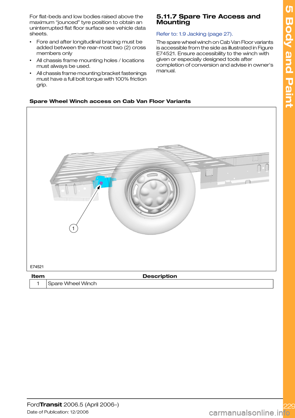
The spare wheel winch on Cab Van Floor variants
is accessible from the side as illustrated in Figure
E74521. Ensure accessibility to the winch with
given or especially designed tools after
completion of conversion and advise in owner's
manual.
Spare Wheel Winch access on Cab Van Floor Variants
DescriptionItem
Spare Wheel Winch1
FordTransit 2006.5 (April 2006–)
Date of Publication: 12/2006
5 Body and Paint
2291E74521