fuse box FORD TRANSIT 2006 7.G Body And Equipment Mounting Section Manual
[x] Cancel search | Manufacturer: FORD, Model Year: 2006, Model line: TRANSIT, Model: FORD TRANSIT 2006 7.GPages: 234, PDF Size: 33.19 MB
Page 116 of 234
4.11 Exterior Lighting
Where the following text makes reference to the
addition of wires
Refer to: 4.14 Special Conversions (page 131).
(Adding Connectors, Terminals and Wiring)
WARNING: Make sure that the
modified vehicle complies with all
relevant legal requirements.
4.11.1 Reversing Lamps
These are hard-wired, activated by the reversing
switch on the transmission and passing through
the Central Junction Box where the signal is
sensed. A marginal increase in current (via a relay
or buffered electrical input) is permissible to
trigger a rear-view camera system, or audible
device.
4.11.2 Additional External Lamps
All power for additional exterior lamps must be
taken through the Auxiliary Fuse Box with a
suitable switch and / or relay as required.
Refer to: 4.13 Fuses and Relays (page 119).
• If CAT 6 directional indicators are to be fitted,
the Central Junction Box will need to be
configured for this.
• The load on the reversing lamps should not
exceed a total of 3A (42W).
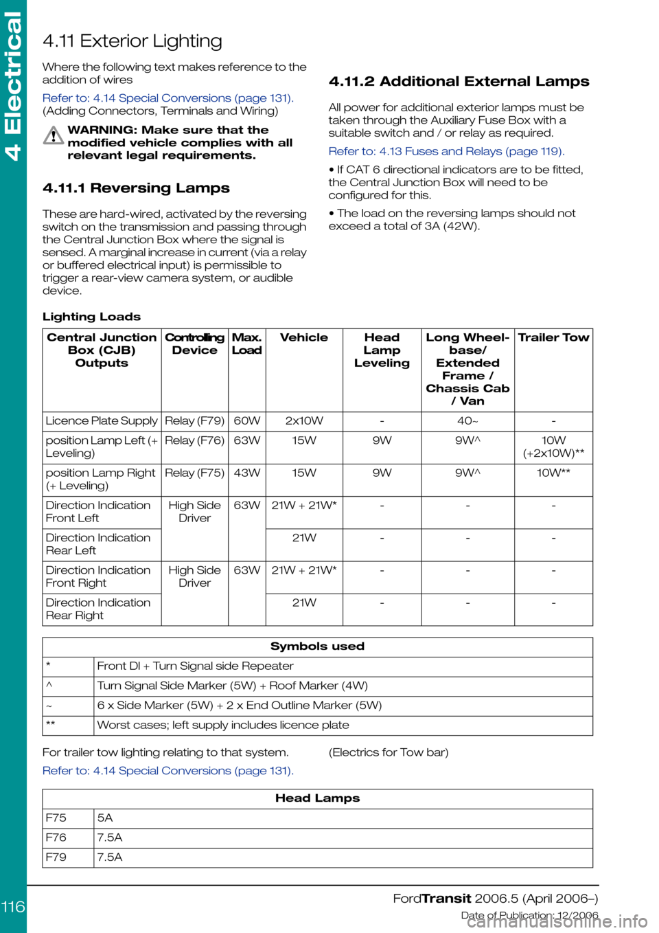
Lighting Loads
Trailer TowLong Wheel-
base/
Extended
Frame /
Chassis Cab
/ Van
Head
Lamp
Leveling
VehicleMax.
Load
Controlling
Device
Central Junction
Box (CJB)
Outputs
-40~-2x10W60WRelay (F79)Licence Plate Supply
10W
(+2x10W)**
9W^9W15W63WRelay (F76)position Lamp Left (+
Leveling)
10W**9W^9W15W43WRelay (F75)position Lamp Right
(+ Leveling)
---21W + 21W*63WHigh Side
Driver
Direction Indication
Front Left
---21WDirection Indication
Rear Left
---21W + 21W*63WHigh Side
Driver
Direction Indication
Front Right
---21WDirection Indication
Rear Right
Symbols used
Front Dl + Turn Signal side Repeater*
Turn Signal Side Marker (5W) + Roof Marker (4W)^
6 x Side Marker (5W) + 2 x End Outline Marker (5W)~
Worst cases; left supply includes licence plate**
For trailer tow lighting relating to that system.
Refer to: 4.14 Special Conversions (page 131).
(Electrics for Tow bar)
Head Lamps
5AF75
7.5AF76
7.5AF79
FordTransit 2006.5 (April 2006–)
Date of Publication: 12/2006
4 Electrical
116
Page 118 of 234
4.12 Interior Lighting
4.12.1 Additional Internal Lamps
Additional cabin interior lighting may be obtained
by directly accessing the connector inside the
dome lamp in the cab.
Additional load space interior lighting may be
obtained by directly accessing the connector
inside the load space lamps in the load space
area.
CAUTION: The maximum total
internal lamp load must not exceed
5A (75W)
Power for the Interior Lights - cabin and
cargo areas – comes from the battery save
system (Central Junction Box pin C2-31), and for
vehicles with power locking,* the circuit for each
area is controlled by a separate pin on the Central
Junction Box:
•Front (cabin) lights, pin C2-22
•Rear (cargo) lights, pin C2-27 wire not present
on chassis cab and cab-van-floor vehicles
* with manual locking vehicles, control of interior
lighting is done directly through the door contact
switches. All vehicles, however, utilise the battery
saver relay to provide power for internal lighting
for a limited time.
Each of these pins on the Central Junction Box
can take a load of 75W. Lights that are controlled
by the battery save circuit will extinguish 30 to
180 minutes after ignition off (dependent on
vehicle configuration).
4.12.2 Additional 'Theatre
Lighting' for rear of vehicle
interior
For chassis cab or cab-van floor (and camper)
vehicles, rear lighting is not utilised and so there
is no wire to pin C2-27. However, converters can
add their own lights (up to the max. load) via the
battery save or a separate switchable feed, by
adding a pre-crimped wire and terminal to
connector C2. This is located on the Central
Junction Box behind the glove box on the
passenger side (please refer to Figures E84705
and E84712).
Refer to: 4.14 Special Conversions (page 131).
(Adding connectors, Terminals and Wiring)
Where higher wattage installations are required,
these should be taken through the Auxiliary Fuse
Box with a suitable switch and / or relay as
required.
Refer to: 4.13 Fuses and Relays (page 119).
FordTransit 2006.5 (April 2006–)
Date of Publication: 12/2006
4 Electrical
118
Page 119 of 234
4.13 Fuses and Relays
4.13.1 Wiring Specification
When designing wire installations for additional
equipment use the cable size recommended by
the equipment manufacturer or select a suitable
size from the Current Rating Wire Sizes
specifications chart.
Refer to: 4.2 (page 94).
Wiring consists a soft annealed copper core in
accordance with DIN 57201 (VDDE 0201)
sheathed in Hypalon or irradiated PVC.
For 0,5mm cable an alternative material with
conductor E-CU F20 or F21 in accordance with
DIN 40500 sheathed in cross linked PVC is
available.
4.13.2 Auxiliary Fuses, Fuse Box
and Relays (Fuses - Standard)
WARNING: No increase in existing
vehicle standard fuse capacity is
allowed under any circumstances.
There are no spare fuses in the
Engine Junction Box, Standard Relay
Box or Central Junction Box. The
vehicle converter/modifier must
provide additional fuses as required.
Please refer to below chart.
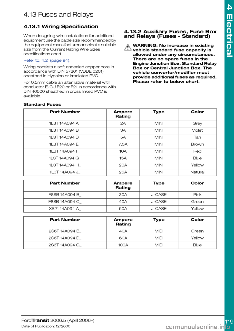
Standard Fuses
ColorTypeAmpere
Rating
Part Number
GreyMINI2A1L3T 14A094 A_
VioletMINI3A1L3T 14A094 B_
TanMINI5A1L3T 14A094 D_
BrownMINI7.5A1L3T 14A094 E_
RedMINI10A1L3T 14A094 F_
BlueMINI15A1L3T 14A094 G_
YellowMINI20A1L3T 14A094 H_
NaturalMINI25A1L3T 14A094 J_
ColorTypeAmpere
Rating
Part Number
PinkJ-CASE30AF8SB 14A094 B_
GreenJ-CASE40AF8SB 14A094 C_
YellowJ-CASE60AXS21 14A094 A_
ColorTypeAmpere
Rating
Part Number
GreenMIDI40A2S6T 14A094 B_
YellowMIDI60A2S6T 14A094 D_
BlueMIDI100A2S6T 14A094 G_
FordTransit 2006.5 (April 2006–)
Date of Publication: 12/2006
4 Electrical
119
Page 120 of 234
4.13.3 Customer Connection Points
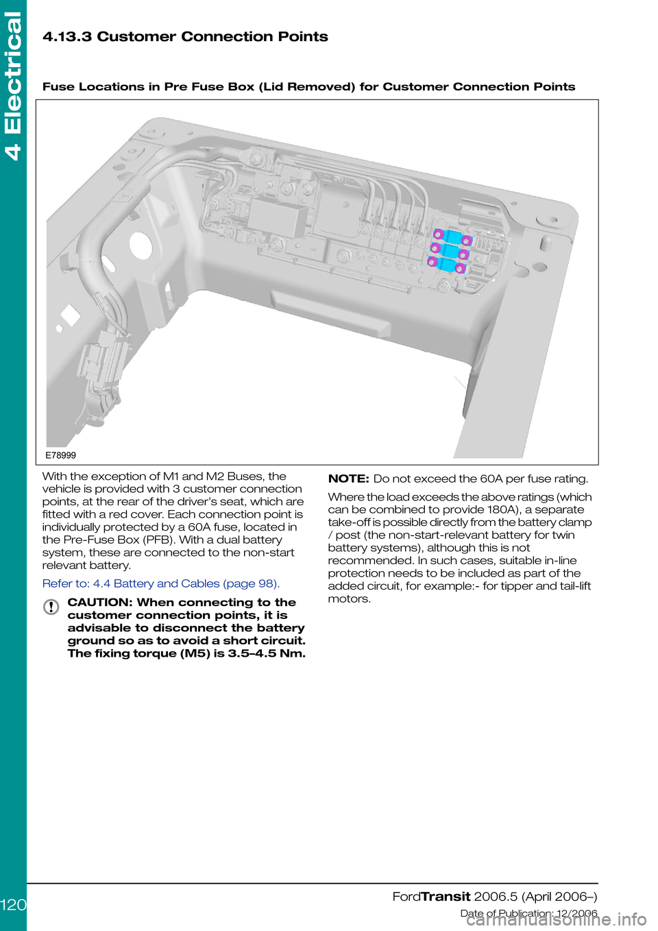
Fuse Locations in Pre Fuse Box (Lid Removed) for Customer Connection Points
With the exception of M1 and M2 Buses, the
vehicle is provided with 3 customer connection
points, at the rear of the driver’s seat, which are
fitted with a red cover. Each connection point is
individually protected by a 60A fuse, located in
the Pre-Fuse Box (PFB). With a dual battery
system, these are connected to the non-start
relevant battery.
Refer to: 4.4 Battery and Cables (page 98).
CAUTION: When connecting to the
customer connection points, it is
advisable to disconnect the battery
ground so as to avoid a short circuit.
The fixing torque (M5) is 3.5–4.5 Nm.
NOTE: Do not exceed the 60A per fuse rating.
Where the load exceeds the above ratings (which
can be combined to provide 180A), a separate
take-off is possible directly from the battery clamp
/ post (the non-start-relevant battery for twin
battery systems), although this is not
recommended. In such cases, suitable in-line
protection needs to be included as part of the
added circuit, for example:- for tipper and tail-lift
motors.
FordTransit 2006.5 (April 2006–)
Date of Publication: 12/2006
4 Electrical
120E78999
Page 121 of 234
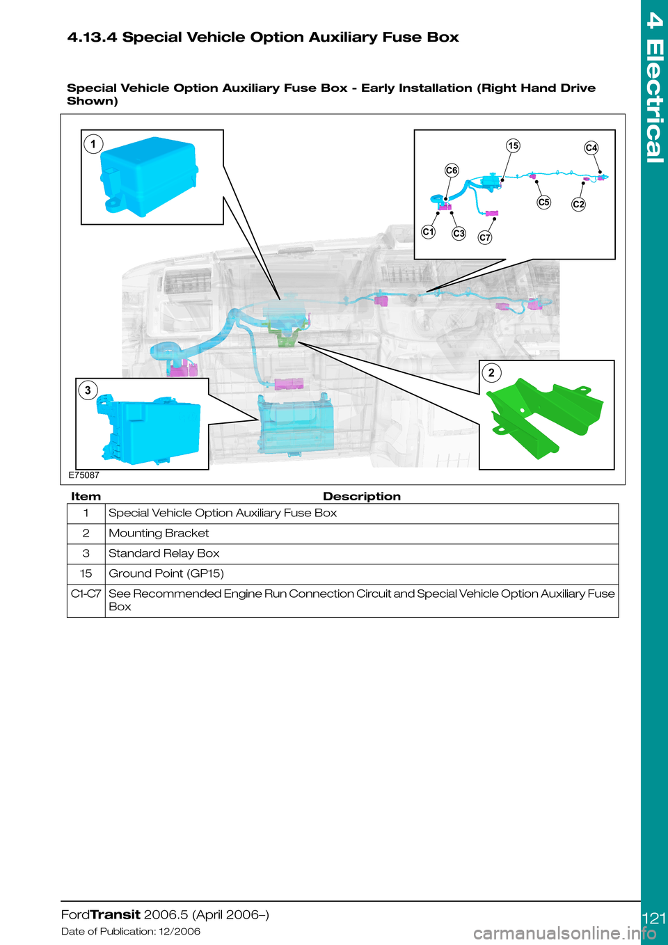
4.13.4 Special Vehicle Option Auxiliary Fuse Box
Special Vehicle Option Auxiliary Fuse Box - Early Installation (Right Hand Drive
Shown)
DescriptionItem
Special Vehicle Option Auxiliary Fuse Box1
Mounting Bracket2
Standard Relay Box3
Ground Point (GP15)15
See Recommended Engine Run Connection Circuit and Special Vehicle Option Auxiliary Fuse
Box
C1-C7
FordTransit 2006.5 (April 2006–)
Date of Publication: 12/2006
4 Electrical
121E75087132
Page 122 of 234
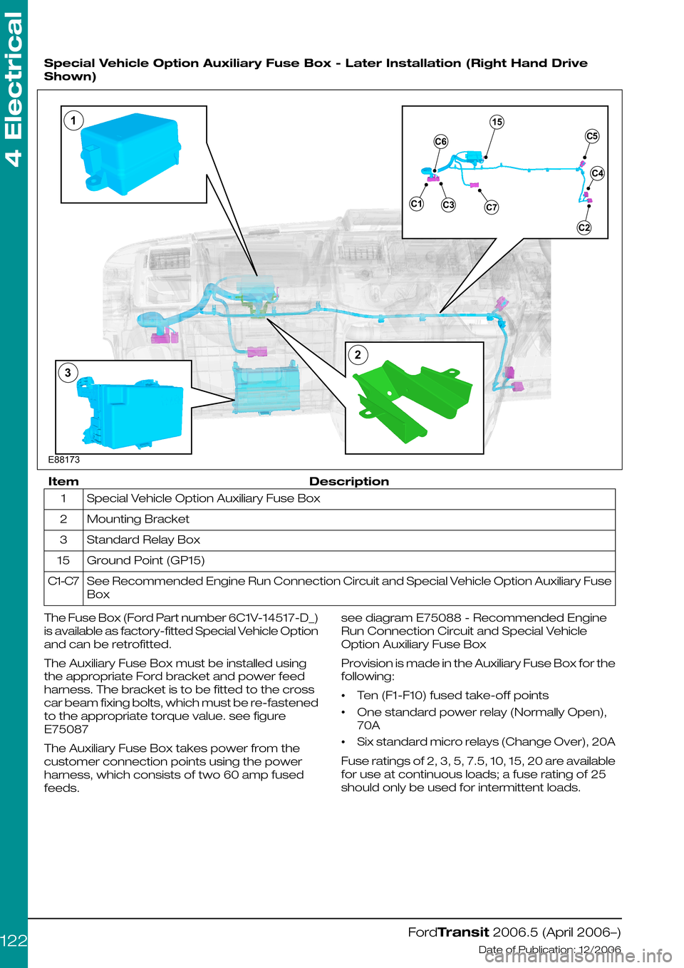
Special Vehicle Option Auxiliary Fuse Box - Later Installation (Right Hand Drive
Shown)
DescriptionItem
Special Vehicle Option Auxiliary Fuse Box1
Mounting Bracket2
Standard Relay Box3
Ground Point (GP15)15
See Recommended Engine Run Connection Circuit and Special Vehicle Option Auxiliary Fuse
Box
C1-C7
The Fuse Box (Ford Part number 6C1V-14517-D_)
is available as factory-fitted Special Vehicle Option
and can be retrofitted.
The Auxiliary Fuse Box must be installed using
the appropriate Ford bracket and power feed
harness. The bracket is to be fitted to the cross
car beam fixing bolts, which must be re-fastened
to the appropriate torque value. see figure
E75087
The Auxiliary Fuse Box takes power from the
customer connection points using the power
harness, which consists of two 60 amp fused
feeds.
see diagram E75088 - Recommended Engine
Run Connection Circuit and Special Vehicle
Option Auxiliary Fuse Box
Provision is made in the Auxiliary Fuse Box for the
following:
•Ten (F1-F10) fused take-off points
•One standard power relay (Normally Open),
70A
•Six standard micro relays (Change Over), 20A
Fuse ratings of 2, 3, 5, 7.5, 10, 15, 20 are available
for use at continuous loads; a fuse rating of 25
should only be used for intermittent loads.
FordTransit 2006.5 (April 2006–)
Date of Publication: 12/2006
4 Electrical
122E88173132
Page 123 of 234
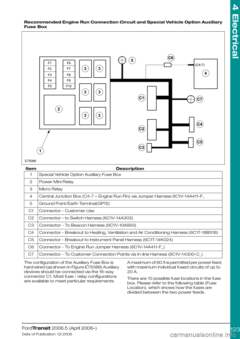
Recommended Engine Run Connection Circuit and Special Vehicle Option Auxiliary
Fuse Box
DescriptionItem
Special Vehicle Option Auxiliary Fuse Box1
Power Mini Relay2
Micro Relay3
Central Junction Box (C4-7 = Engine Run Pin) via Jumper Harness 6C1V-14A411-F_4
Ground Point/Earth Terminal(GP15)5
Connector - Customer UseC1
Connector - to Switch Harness (6C1V-14A303)C2
Connector - To Beacon Harness (6C1V-10A993)C3
Connector - Breakout to Heating, Ventilation and Air Conditioning Harness (6C1T-18B518)C4
Connector - Breakout to Instrument Panel Harness (6C1T-14K024)C5
Connector - To Engine Run Jumper Harness (6C1V-14A411-F_)C6
Connector - To Customer Connection Points via In-line Harness (6C1V-14300-C_)C7
The configuration of the Auxiliary Fuse Box is
hard wired (as shown in Figure E75088) Auxiliary
devices should be connected via the 16-way
connector C1. Most fuse / relay configurations
are available to meet particular requirements.
A maximum of 60 A is permitted per power feed,
with maximum individual fused circuits of up to
20 A.
There are 10 possible fuse locations in the fuse
box. Please refer to the following table (Fuse
Location), which shows how the fuses are
divided between the two power feeds.
FordTransit 2006.5 (April 2006–)
Date of Publication: 12/2006
4 Electrical
123E75088
Page 124 of 234
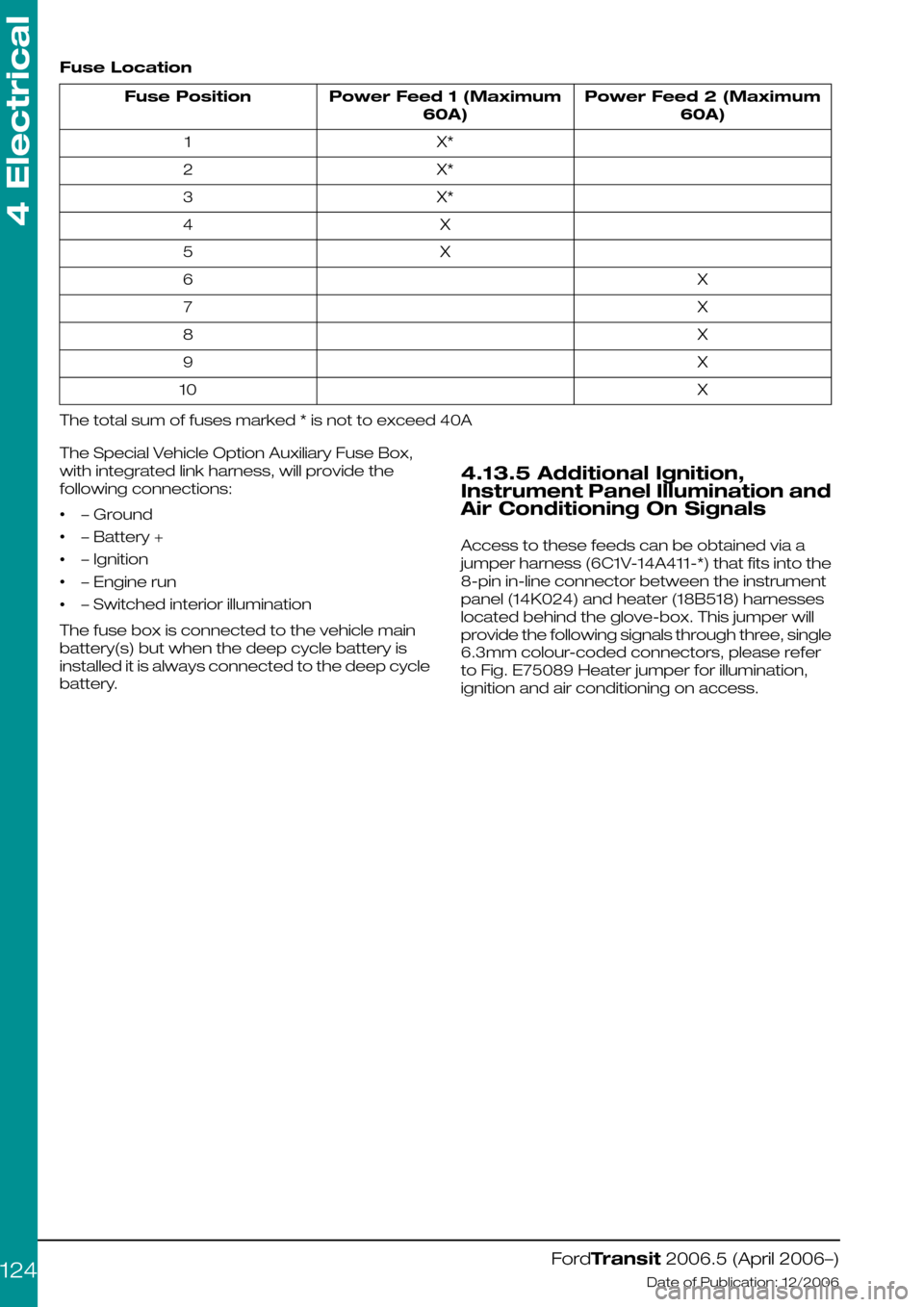
Fuse Location
Power Feed 2 (Maximum
60A)
Power Feed 1 (Maximum
60A)
Fuse Position
X*1
X*2
X*3
X4
X5
X6
X7
X8
X9
X10
The total sum of fuses marked * is not to exceed 40A
The Special Vehicle Option Auxiliary Fuse Box,
with integrated link harness, will provide the
following connections:
•– Ground
•– Battery +
•– Ignition
•– Engine run
•– Switched interior illumination
The fuse box is connected to the vehicle main
battery(s) but when the deep cycle battery is
installed it is always connected to the deep cycle
battery.
4.13.5 Additional Ignition,
Instrument Panel Illumination and
Air Conditioning On Signals
Access to these feeds can be obtained via a
jumper harness (6C1V-14A411-*) that fits into the
8-pin in-line connector between the instrument
panel (14K024) and heater (18B518) harnesses
located behind the glove-box. This jumper will
provide the following signals through three, single
6.3mm colour-coded connectors, please refer
to Fig. E75089 Heater jumper for illumination,
ignition and air conditioning on access.
FordTransit 2006.5 (April 2006–)
Date of Publication: 12/2006
4 Electrical
124
Page 125 of 234
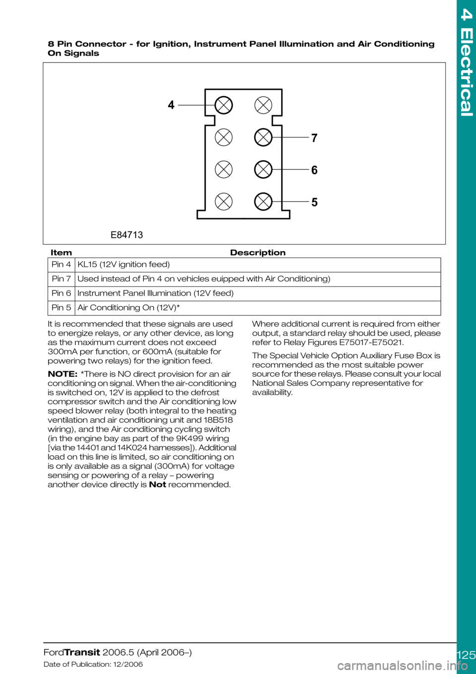
8 Pin Connector - for Ignition, Instrument Panel Illumination and Air Conditioning
On Signals
DescriptionItem
KL15 (12V ignition feed)Pin 4
Used instead of Pin 4 on vehicles euipped with Air Conditioning)Pin 7
Instrument Panel Illumination (12V feed)Pin 6
Air Conditioning On (12V)*Pin 5
It is recommended that these signals are used
to energize relays, or any other device, as long
as the maximum current does not exceed
300mA per function, or 600mA (suitable for
powering two relays) for the ignition feed.
NOTE: *There is NO direct provision for an air
conditioning on signal. When the air-conditioning
is switched on, 12V is applied to the defrost
compressor switch and the Air conditioning low
speed blower relay (both integral to the heating
ventilation and air conditioning unit and 18B518
wiring), and the Air conditioning cycling switch
(in the engine bay as part of the 9K499 wiring
[via the 14401 and 14K024 harnesses]). Additional
load on this line is limited, so air conditioning on
is only available as a signal (300mA) for voltage
sensing or powering of a relay – powering
another device directly is Not recommended.
Where additional current is required from either
output, a standard relay should be used, please
refer to Relay Figures E75017-E75021.
The Special Vehicle Option Auxiliary Fuse Box is
recommended as the most suitable power
source for these relays. Please consult your local
National Sales Company representative for
availability.
FordTransit 2006.5 (April 2006–)
Date of Publication: 12/2006
4 Electrical
1254E84713765
Page 127 of 234
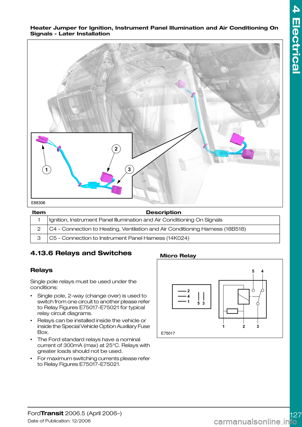
Heater Jumper for Ignition, Instrument Panel Illumination and Air Conditioning On
Signals - Later Installation
DescriptionItem
Ignition, Instrument Panel Illumination and Air Conditioning On Signals1
C4 - Connection to Heating, Ventilation and Air Conditioning Harness (18B518)2
C5 - Connection to Instrument Panel Harness (14K024)3
4.13.6 Relays and Switches
Relays
Single pole relays must be used under the
conditions:
•Single pole, 2-way (change over) is used to
switch from one circuit to another please refer
to Relay Figures E75017-E75021 for typical
relay circuit diagrams.
•Relays can be installed inside the vehicle or
inside the Special Vehicle Option Auxiliary Fuse
Box.
•The Ford standard relays have a nominal
current of 300mA (max) at 25°C. Relays with
greater loads should not be used.
•For maximum switching currents please refer
to Relay Figures E75017-E75021.
Micro Relay
FordTransit 2006.5 (April 2006–)
Date of Publication: 12/2006
4 Electrical
127E88306123 E750171425312354