roof FORD TRANSIT 2006 7.G Body And Equipment Mounting Section Manual
[x] Cancel search | Manufacturer: FORD, Model Year: 2006, Model line: TRANSIT, Model: FORD TRANSIT 2006 7.GPages: 234, PDF Size: 33.19 MB
Page 196 of 234
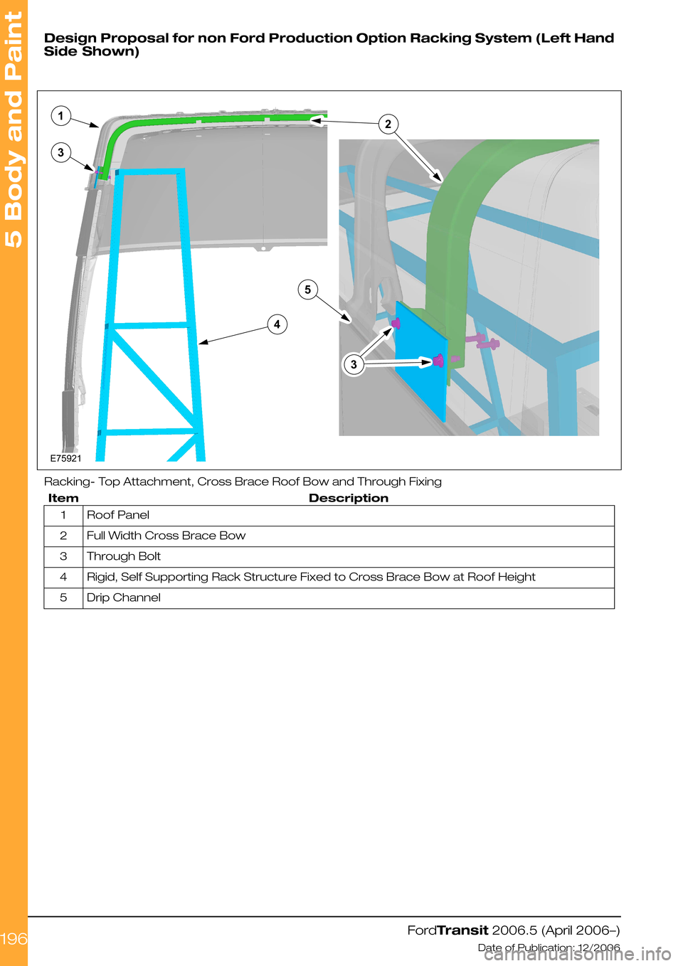
Design Proposal for non Ford Production Option Racking System (Left Hand
Side Shown)
Racking- Top Attachment, Cross Brace Roof Bow and Through Fixing
DescriptionItem
Roof Panel1
Full Width Cross Brace Bow2
Through Bolt3
Rigid, Self Supporting Rack Structure Fixed to Cross Brace Bow at Roof Height4
Drip Channel5
FordTransit 2006.5 (April 2006–)
Date of Publication: 12/2006
5 Body and Paint
196E75921213435
Page 214 of 234
5.7 Roof Opening Panel
5.7.1 Driver's Standing Head
Room
When planning cab walk-through capability on a
Van, Bus or Kombi, select the Special Vehicle
option, which replaces the front headlining and
parcel shelf in Vans and provides the maximum
height headlining for increased standing head
room height.
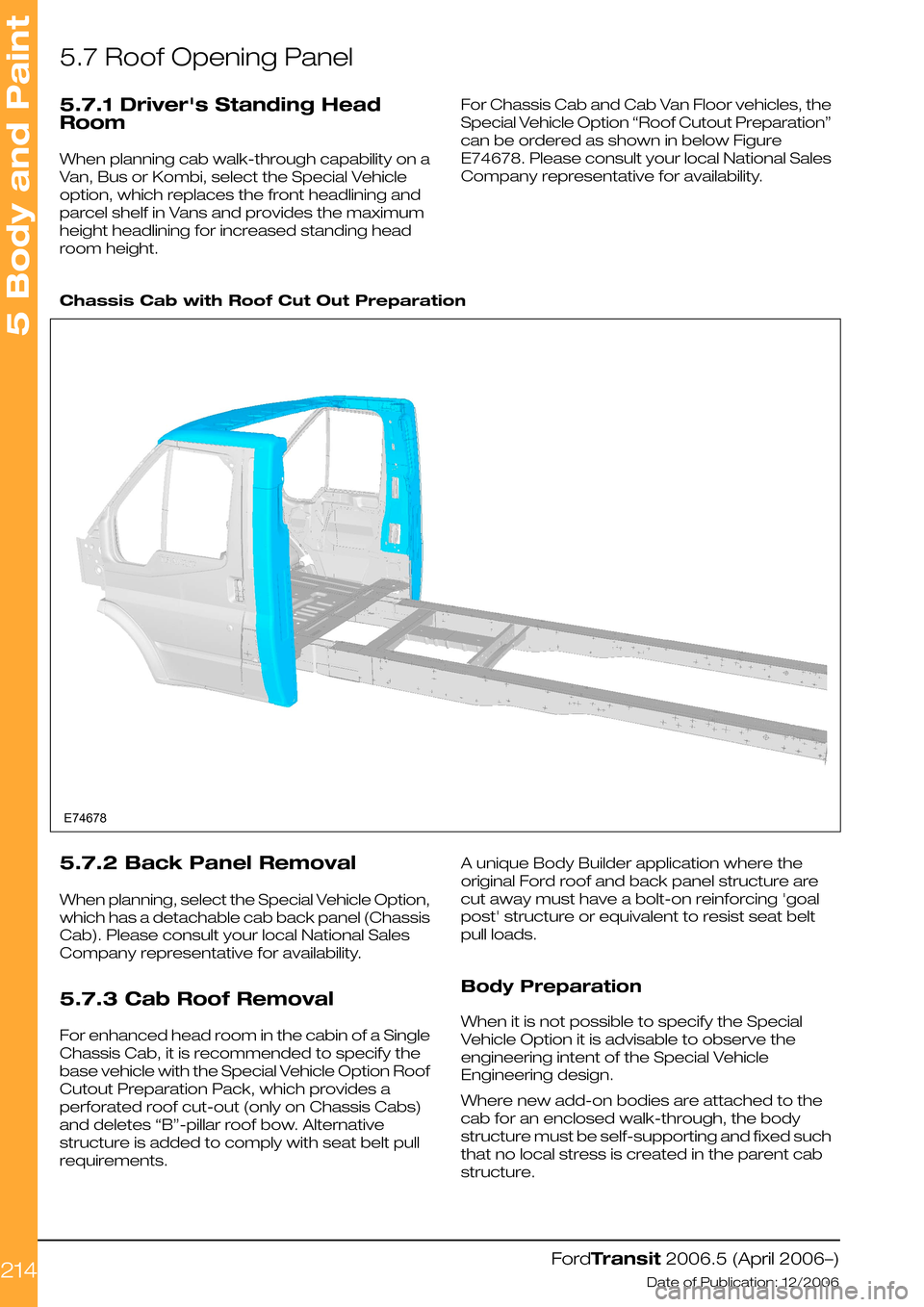
For Chassis Cab and Cab Van Floor vehicles, the
Special Vehicle Option “Roof Cutout Preparation”
can be ordered as shown in below Figure
E74678. Please consult your local National Sales
Company representative for availability.
Chassis Cab with Roof Cut Out Preparation
5.7.2 Back Panel Removal
When planning, select the Special Vehicle Option,
which has a detachable cab back panel (Chassis
Cab). Please consult your local National Sales
Company representative for availability.
5.7.3 Cab Roof Removal
For enhanced head room in the cabin of a Single
Chassis Cab, it is recommended to specify the
base vehicle with the Special Vehicle Option Roof
Cutout Preparation Pack, which provides a
perforated roof cut-out (only on Chassis Cabs)
and deletes “B”-pillar roof bow. Alternative
structure is added to comply with seat belt pull
requirements.
A unique Body Builder application where the
original Ford roof and back panel structure are
cut away must have a bolt-on reinforcing 'goal
post' structure or equivalent to resist seat belt
pull loads.
Body Preparation
When it is not possible to specify the Special
Vehicle Option it is advisable to observe the
engineering intent of the Special Vehicle
Engineering design.
Where new add-on bodies are attached to the
cab for an enclosed walk-through, the body
structure must be self-supporting and fixed such
that no local stress is created in the parent cab
structure.
FordTransit 2006.5 (April 2006–)
Date of Publication: 12/2006
5 Body and Paint
214E74678
Page 215 of 234
Use metal fasteners through double thickness
flanges for example with nuts, bolts and spreader
plates where possible.
“Pop” type rivet structural value is only as good
as the material or thickness of the body panels,
therefore ensure the application is suitably
engineered.
Protect all metal edges to comply with interior
projection legislation.
Corrosion protect all cut or drilled metal edges
and repair any paint damage.
5.7.4 Roof Ventilation
General
Apertures must not cut through roof bows.
Ventilators must prevent direct entry of water
and dust.
A shut-off system should be available to prevent
fume ingress.
Interior and exterior projection legal requirements
must be maintained.
Sun Roof
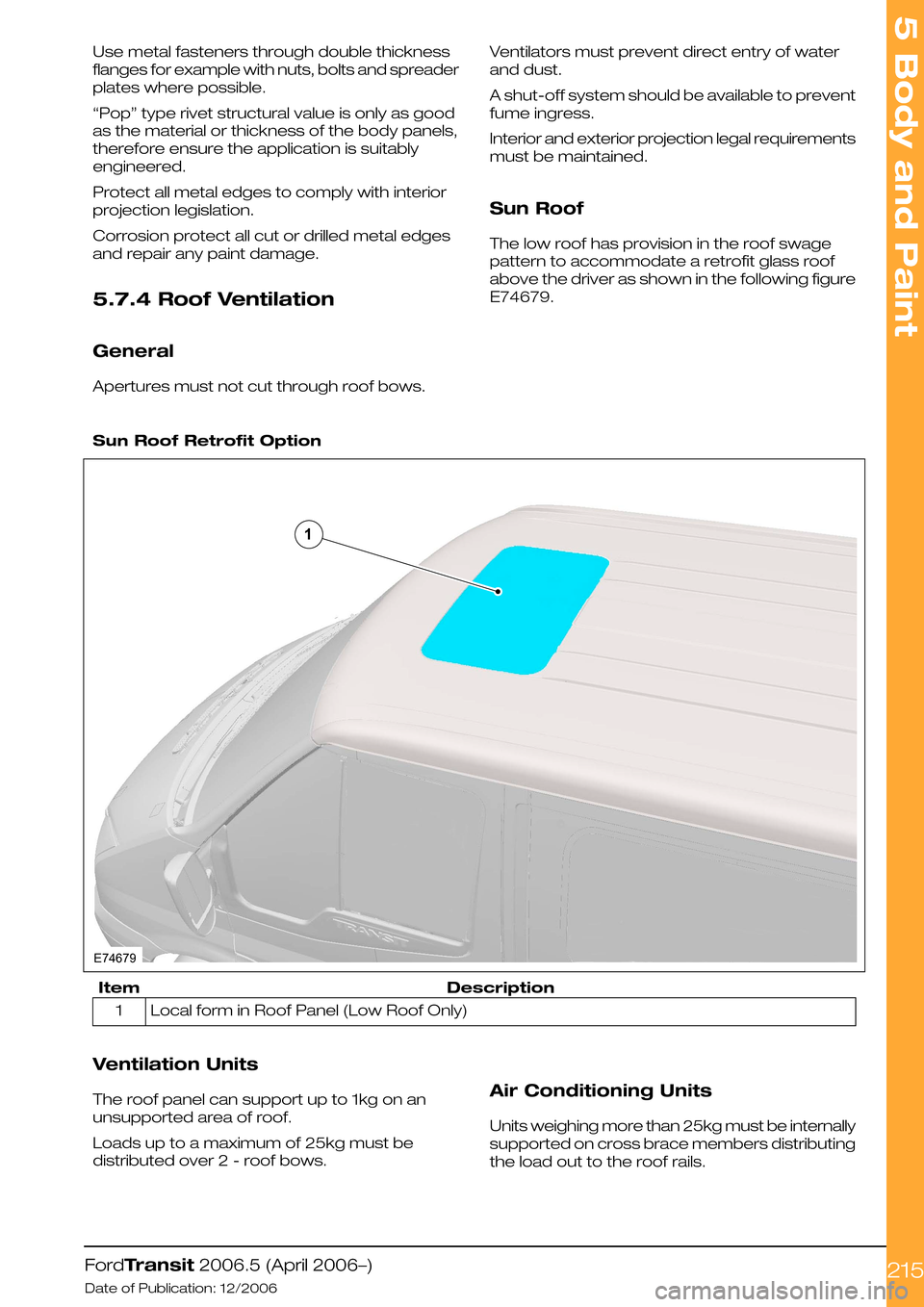
The low roof has provision in the roof swage
pattern to accommodate a retrofit glass roof
above the driver as shown in the following figure
E74679.
Sun Roof Retrofit Option
DescriptionItem
Local form in Roof Panel (Low Roof Only)1
Ventilation Units
The roof panel can support up to 1kg on an
unsupported area of roof.
Loads up to a maximum of 25kg must be
distributed over 2 - roof bows.
Air Conditioning Units
Units weighing more than 25kg must be internally
supported on cross brace members distributing
the load out to the roof rails.
FordTransit 2006.5 (April 2006–)
Date of Publication: 12/2006
5 Body and Paint
215E746791
Page 216 of 234
5.7.5 Roof Racks
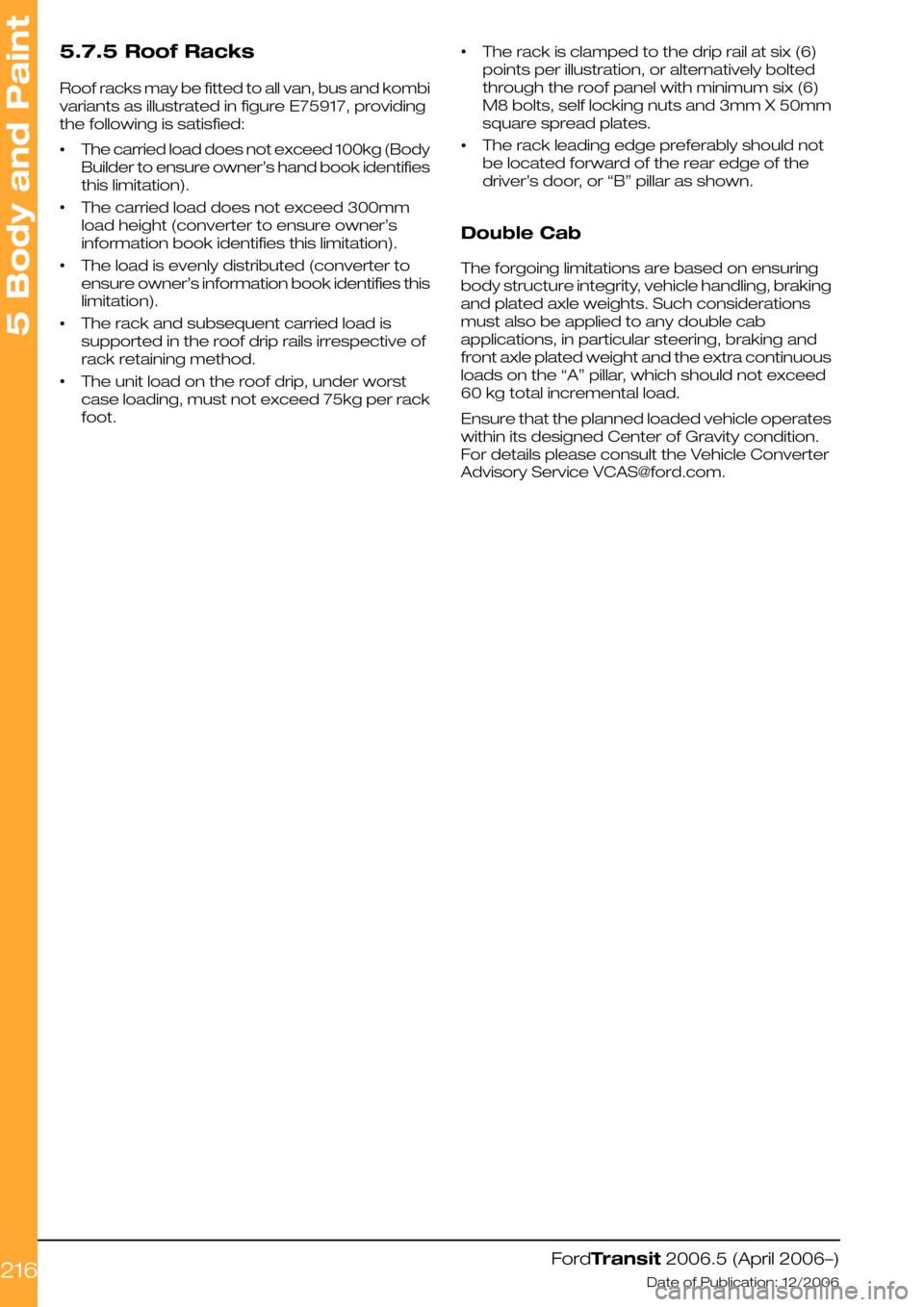
Roof racks may be fitted to all van, bus and kombi
variants as illustrated in figure E75917, providing
the following is satisfied:
•The carried load does not exceed 100kg (Body
Builder to ensure owner’s hand book identifies
this limitation).
•The carried load does not exceed 300mm
load height (converter to ensure owner’s
information book identifies this limitation).
•The load is evenly distributed (converter to
ensure owner’s information book identifies this
limitation).
•The rack and subsequent carried load is
supported in the roof drip rails irrespective of
rack retaining method.
•The unit load on the roof drip, under worst
case loading, must not exceed 75kg per rack
foot.
•The rack is clamped to the drip rail at six (6)
points per illustration, or alternatively bolted
through the roof panel with minimum six (6)
M8 bolts, self locking nuts and 3mm X 50mm
square spread plates.
•The rack leading edge preferably should not
be located forward of the rear edge of the
driver’s door, or “B” pillar as shown.
Double Cab
The forgoing limitations are based on ensuring
body structure integrity, vehicle handling, braking
and plated axle weights. Such considerations
must also be applied to any double cab
applications, in particular steering, braking and
front axle plated weight and the extra continuous
loads on the “A” pillar, which should not exceed
60 kg total incremental load.
Ensure that the planned loaded vehicle operates
within its designed Center of Gravity condition.
For details please consult the Vehicle Converter
Advisory Service [email protected].
FordTransit 2006.5 (April 2006–)
Date of Publication: 12/2006
5 Body and Paint
216
Page 217 of 234
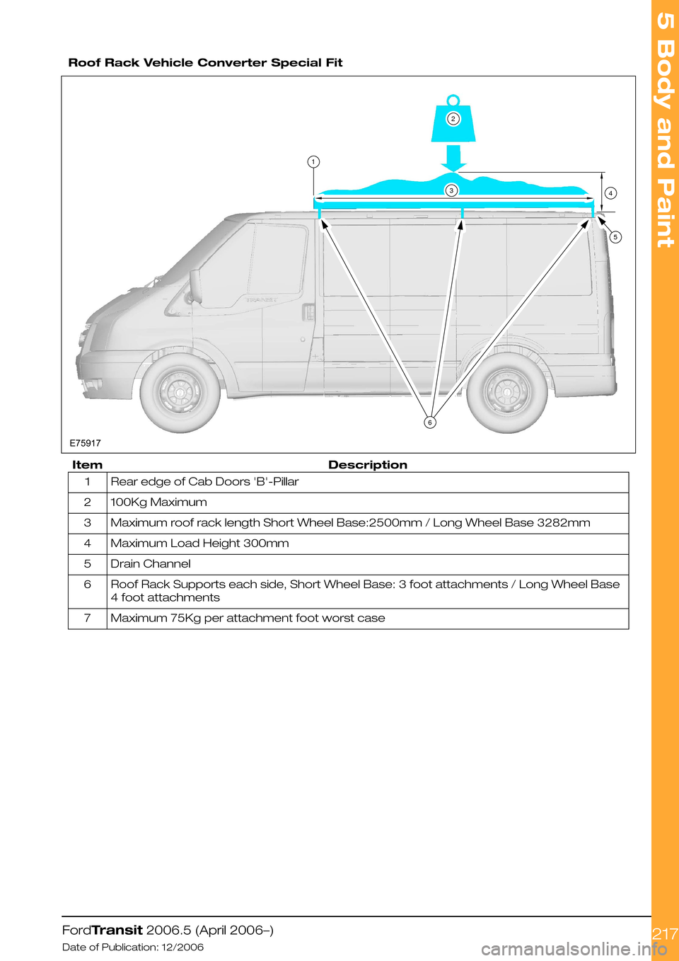
Roof Rack Vehicle Converter Special Fit
DescriptionItem
Rear edge of Cab Doors 'B'-Pillar1
100Kg Maximum2
Maximum roof rack length Short Wheel Base:2500mm / Long Wheel Base 3282mm3
Maximum Load Height 300mm4
Drain Channel5
Roof Rack Supports each side, Short Wheel Base: 3 foot attachments / Long Wheel Base
4 foot attachments
6
Maximum 75Kg per attachment foot worst case7
FordTransit 2006.5 (April 2006–)
Date of Publication: 12/2006
5 Body and Paint
217123564E75917
Page 230 of 234
A
About This Manual................................................6
Accessory Drive..................................................77
Adding Connectors, Terminals and Wiring....
162
Additional 'Theatre Lighting' for rear of vehicle
interior...............................................................118
Additional External Lamps...............................116
Additional Ignition, Instrument Panel Illumination
and Air Conditioning On Signals...................124
Additional Internal Lamps ................................118
Additional Vehicle Signals / Features.............147
Aids for Vehicle Entry and Exit..........................33
Air Bags..............................................................218
Air Bag Supplemental Restraint System (SRS)..
218
Air Flow Restrictions...........................................76
Alternative Type Approval....................................7
Ancillary Equipment - Sub Frame Mounting....
228
Antenna Location...............................................24
Anti-Lock Control - Stability Assist..................65
Auxiliary Fuses, Fuse Box and Relays (Fuses -
Standard)..........................................................119
Auxiliary Heater Installation...............................76
Auxiliary Heater Systems..................................75
B
Back Panel Removal................................177, 214
Battery and Cables............................................98
Battery Information............................................98
Body....................................................................175
Body Closures..................................................203
Body Structures - General Information.........175
Body System - General
Information—Specifications.........................200
Brake Hoses General........................................62
Brake System.....................................................62
C
Cab Roof Removal...........................................214
Cab Van Floor....................................................185
CAN-Bus System Description and Interface....
90
Cellular Phone....................................................115
Center of Gravity ...............................................46
Central Junction Box (CJB)...............................91
Charge Balance Guidelines..............................97
Charging System...............................................95
Chassis Cab.......................................................179
Circit Diagram.....................................................94
Circuit Diagram...................................................93
Circuit Diagrams.................................................97
Climate Control System..................................106
Clutch...................................................................82
Commercial and Legal Aspects.........................7
Communications Network...............................90
Connectors........................................................133
Contact Corrosion............................................221
Contact Information.............................................9
Conversion Affect on Fuel Economy and
Performance.....................................................25
Conversion Affects on Parking Aids................33
Conversion Homologation...............................23
Conversion Type.................................................14
Corrosion Prevention.......................................221
Customer Connection Points.........................120
D
Drilling and Welding..............................................8
Driver's Standing Head Room........................214
Driver Field of View.............................................33
Driver Reach Zones...........................................33
Driveshaft.............................................................61
E
Electrical Conversions.......................................95
Electrically operated Door Mirrors..................117
Electrics for Tow bar........................................136
Electromagnetic Compatibility (EMC)............24
Electronic Engine Controls................................81
End of Life Vehicle (ELV) Directive...................26
Engine Cooling....................................................75
Engine..................................................................66
Engine Power Curves.......................................66
Engine RPM (Revs Per Minute) Speed
Controller..........................................................157
Engine Run Signal (D+ Alternative)................132
Exhaust Heat Shields.........................................86
Exhaust Pipes and Supports............................86
Exhaust System.................................................86
Extended Chassis Frame...............................226
Extensions and Optional Exhausts..................86
Exterior Lighting.................................................116
F
Fitting of Equipment Containing an Electric
Motor..................................................................97
Frame and Body Mounting............................222
Frame Drilling and Tube Reinforcing.............228
Front, Rear and Side Under-run Protection....
38
Front and Rear Brakes......................................64
Front End Accessory Drive 2.2l Diesel............79
Front End Accessory Drive 2.4l Diesel and 2.3l
Petrol...................................................................77
Front End Integrity for Cooling, Crash,
Aerodynamics and Lighting..........................198
Front Suspension...............................................58
Fuel System........................................................88
Fuses and Relays..............................................119
G
General........................................................62, 221
General Component Package Guidelines.....33
General Information and Specific Warnings....
95
General........................................................62, 221
General Product Safety Requirement...............7
Index
230
Page 231 of 234
Generator and Alternator...............................103
Glass, Frames and Mechanisms...................211
Ground Points..................................................140
H
Hardware—Specifications...............................43
Heated Seats...................................................210
Heated Windshield and Heated Rear Window.
213
Horn...................................................................108
How to Use This Manual....................................6
Hydraulic Brake Actuation...............................64
Hydraulic Lifting Equipment for Van, Bus, Kombi
and Chassis Cab...........................................186
I
Important Safety Instructions............................6
Information and Entertainment System -
General Information—Specifications...........112
Installation and Routing Guides.....................134
Instrument Cluster...........................................107
Integrated Bodies and Conversions.............177
Interior Lighting.................................................118
Introduction..........................................................6
J
Jacking................................................................27
K
Kerb Mass Data.................................................62
L
Lamps for Wide Vehicles.................................117
Lamps – Front and Rear Fog Lights..............117
Lamps – Hazard / Direction Indication..........117
Legal and Vehicle Type Approval......................7
Legal Obligations and Liabilities.........................7
Legislation.........................................................109
Lifting...................................................................29
Load Apportioning Valves................................64
Load Compartment Interior Lining...............203
Load Distribution—Specifications...................44
Load Distribution Calculations - Driver and
Passenger Weight Distribution.....................44
M
Manual Transmission........................................83
Minimum Requirements for Brake system and
Load Apportioning Valves ...............................8
Mirrors for Wide Vehicles...............................208
Module Communications
Network—Specifications................................94
Mounting Points and Tubing.........................222
N
Noise, Vibration and Harshness (NVH)...........31
Non Standard Rear Chassis Frame Extension.
226
P
Package and Ergonomics—Specifications....
34
Package and Ergonomics...............................33
Painting Road Wheels..............................60, 221
Parking Brake....................................................63
Partitions (Bulkhead) - Driver and Front
Passenger(s) Protection on Van, Bus and
Kombi..............................................................192
Possible Accessories.......................................113
Power Management Settings.........................95
Power Take Off...................................................61
Product Liability....................................................8
R
Racking Systems.............................................194
Radio Connector..............................................112
Rear Anti-Roll Bar..............................................59
Rear Seat Fixings Positions - Kombi............209
Rear Suspension...............................................59
Rear View Mirrors...........................................208
Rear Windows..................................................211
Recommended Main Dimensions.................34
Recommended Main Load Area Dimensions
for Bulkhead with Depression Driver Side....
39
Recommended Main Load Area Dimensions
for Bulkhead with Full Depression................40
Recommended Main Load Area Dimensions
for Double Cab In Van Bulkhead...................41
Recommended Nominal Body Lengths for
Chassis Cab models......................................36
Relays and Switches.......................................127
Relocated Parking Brake Lever......................63
Repairing Damaged Paint..............................221
Restraints System...............................................8
Reversing Lamps.............................................116
Road Safety..........................................................8
Roof Opening Panel........................................214
Roof Racks.......................................................216
Roof Ventilation................................................215
S
Safety Belt System.........................................220
Seats.................................................................209
Security, Anti Theft and Locking System
Security ..........................................................203
Self-Supporting Body Structure...................224
Spare Tire Access and Mounting.................229
Spare wheel.......................................................60
Special Conversions........................................131
Special Vehicle Option Auxiliary Fuse Box....
121
Index
231