ECU FORD TRANSIT 2006 7.G Body And Equipment Mounting Section Manual
[x] Cancel search | Manufacturer: FORD, Model Year: 2006, Model line: TRANSIT, Model: FORD TRANSIT 2006 7.GPages: 234, PDF Size: 33.19 MB
Page 4 of 234
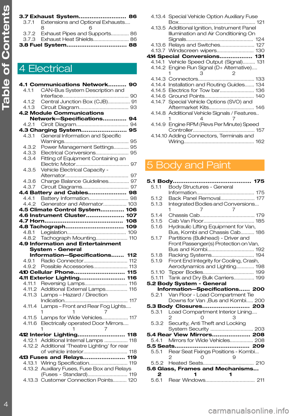
3.7Exhaust System..........................86
3.7.1Extensions and Optional Exhausts....
86
3.7.2Exhaust Pipes and Supports.............86
3.7.3Exhaust Heat Shields..........................86
3.8Fuel System.................................88
4 Electrical
4.1Communications Network..........90
4.1.1CAN-Bus System Description and
Interface................................................90
4.1.2Central Junction Box (CJB)................91
4.1.3Circuit Diagram....................................93
4.2Module Communications
Network—Specifications.............94
4.2.1Circit Diagram......................................94
4.3Charging System.........................95
4.3.1General Information and Specific
Warnings...............................................95
4.3.2Power Management Settings...........95
4.3.3Electrical Conversions........................95
4.3.4Fitting of Equipment Containing an
Electric Motor.......................................97
4.3.5Vehicle Electrical Capacity -
Alternator..............................................97
4.3.6Charge Balance Guidelines...............97
4.3.7Circuit Diagrams..................................97
4.4Battery and Cables.....................98
4.4.1Battery Information.............................98
4.4.2Generator and Alternator.................103
4.5Climate Control System.............106
4.6Instrument Cluster.....................107
4.7Horn...........................................108
4.8Tachograph................................109
4.8.1Legislation...........................................109
4.8.2Tachograph Mounting.......................110
4.9Information and Entertainment
System - General
Information—Specifications.......112
4.9.1Radio Connector................................112
4.9.2Possible Accessories.........................113
4.10Cellular Phone............................115
4.11Exterior Lighting.........................116
4.11.1Reversing Lamps...............................116
4.11.2Additional External Lamps................116
4.11.3Lamps – Hazard / Direction
Indication..............................................117
4.11.4Lamps – Front and Rear Fog Lights....
117
4.11.5Lamps for Wide Vehicles...................117
4.11.6Electrically operated Door Mirrors....
117
4.12Interior Lighting..........................118
4.12.1Additional Internal Lamps .................118
4.12.2Additional 'Theatre Lighting' for rear
of vehicle interior................................118
4.13Fuses and Relays.......................119
4.13.1Wiring Specification............................119
4.13.2Auxiliary Fuses, Fuse Box and Relays
(Fuses - Standard).............................119
4.13.3Customer Connection Points..........120
4.13.4Special Vehicle Option Auxiliary Fuse
Box........................................................121
4.13.5Additional Ignition, Instrument Panel
Illumination and Air Conditioning On
Signals.................................................124
4.13.6Relays and Switches.........................127
4.13.7Windscreen wipers...........................130
4.14Special Conversions..................131
4.14.1Vehicle Speed Output (Signal).........131
4.14.2Engine Run Signal (D+ Alternative)....
132
4.14.3Connectors.........................................133
4.14.4Installation and Routing Guides.......134
4.14.5Electrics for Tow bar.........................136
4.14.6Ground Points....................................140
4.14.7Special Vehicle Options (SVO) and
Aftermarket Kits.................................146
4.14.8Additional Vehicle Signals / Features..
147
4.14.9Engine RPM (Revs Per Minute) Speed
Controller.............................................157
4.14.10Adding Connectors, Terminals and
Wiring...................................................162
5 Body and Paint
5.1Body...........................................175
5.1.1Body Structures - General
Information..........................................175
5.1.2Back Panel Removal.........................177
5.1.3Integrated Bodies and Conversions...
177
5.1.4Chassis Cab........................................179
5.1.5Cab Van Floor.....................................185
5.1.6Hydraulic Lifting Equipment for Van,
Bus, Kombi and Chassis Cab..........186
5.1.7Partitions (Bulkhead) - Driver and
Front Passenger(s) Protection on Van,
Bus and Kombi..................................192
5.1.8Racking Systems...............................194
5.1.9Front End Integrity for Cooling, Crash,
Aerodynamics and Lighting.............198
5.1.10Tipper Bodies.....................................199
5.1.11Tank and Dry Bulk Carriers...............199
5.2Body System - General
Information—Specifications......200
5.2.1Van Floor - Load Compartment Tie
Downs for Van ,Bus and Kombi.....200
5.3Body Closures..........................203
5.3.1Load Compartment Interior Lining....
203
5.3.2Security, Anti Theft and Locking
System Security ...............................203
5.4Rear View Mirrors.....................208
5.4.1Mirrors for Wide Vehicles.................208
5.5Seats.........................................209
5.5.1Rear Seat Fixings Positions - Kombi...
209
5.5.2Heated Seats.....................................210
5.6Glass, Frames and Mechanisms...
211
5.6.1Rear Windows....................................211
Table of Contents
4
Page 29 of 234
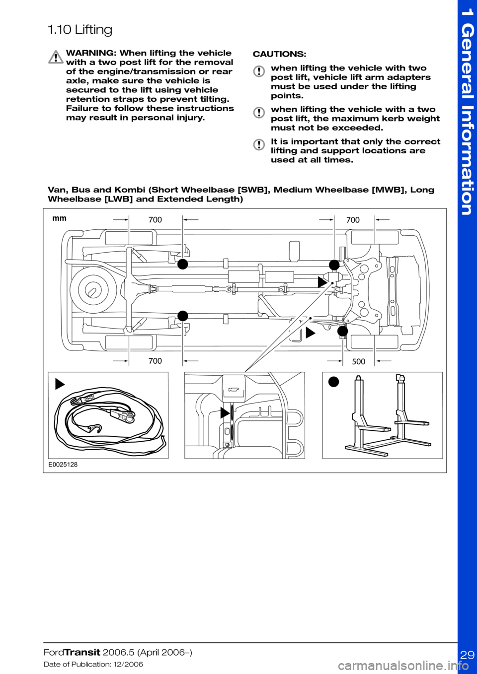
1.10 Lifting
WARNING: When lifting the vehicle
with a two post lift for the removal
of the engine/transmission or rear
axle, make sure the vehicle is
secured to the lift using vehicle
retention straps to prevent tilting.
Failure to follow these instructions
may result in personal injury.
CAUTIONS:
when lifting the vehicle with two
post lift, vehicle lift arm adapters
must be used under the lifting
points.
when lifting the vehicle with a two
post lift, the maximum kerb weight
must not be exceeded.
It is important that only the correct
lifting and support locations are
used at all times.
Van, Bus and Kombi (Short Wheelbase [SWB], Medium Wheelbase [MWB], Long
Wheelbase [LWB] and Extended Length)
FordTransit 2006.5 (April 2006–)
Date of Publication: 12/2006
1 General Information
29E0025128
Page 62 of 234
2.6 Brake System
2.6.1 General
The Brake System must be fully functional when
the vehicle conversion is completed. The vehicle
brake operating modes must be checked,
including warning system and parking brakes.
Brakes are certified to 71/320EEC and ECE R13
requirements as amended.
WARNING: Do not restrict the airflow
and cooling to the brake system
CAUTION: Spoilers and wheel covers
must not affect the brake cooling
performance.
NOTE: Do not obstruct the view of the brake
fluid reservoir level
NOTE: The donor vehicle brake fluid reservoir is
translucent so that it is possible to check the level
of fluid without opening the reservoir which will
reduce the risk of contamination.
The brake fluid reservoir must remain accessible
for servicing and for adding brake fluid.
2.6.2 Kerb Mass Data
NOTE: For further information please contact
your local National Sales Company representative,
or Local Ford Dealer. If they are unable to help
you then please contact the Vehicle Converter
Advisory Service at [email protected].
2.6.3 Brake Hoses General
CAUTION: Make sure that the front
and rear brake hoses are not
twisted and are correctly located
away from body and chassis
components.
Front and rear brake hoses must not rub, chafe
or rest on body or chassis components. There
must be clearance under all operating conditions,
between full compression and extension and full
lock to lock.
Brake lines must not be used to support or
secure any other component.
FordTransit 2006.5 (April 2006–)
Date of Publication: 12/2006
2 Chassis
62
Page 75 of 234
3.2 Engine Cooling
3.2.1 Auxiliary Heater Systems
WARNINGS:
Ford coolant additives are
necessary for the complete function
of the system. Only use ford
approved or equivalent specification
component, to withstand any
detrimental effects on the materials.
Do not mount components in front
of the grille or in an area of air flow
around the engine, which could
affect the engine cooling.
CAUTIONS:
Only make connections into the
heater hose between the front cab
heater and water pump return inlet.
Do not exceed the vehicle's original
coolant volume by more than 10%
Only use the manufactures
recommended (or equivalent
specification) coolant
additives/anti-freeze. Do not mix
coolant types.
•Coolant flow to cab heater must have priority
over flow to auxiliary heater or hand wash
facility.
•Coolant tube routing must be below the base
of the degas bottle.
•Use aluminum or plastic tee junction with
swaged or beaded ends to prevent hose blow
off. Reconnect original coolant tube as shown
in view E74570 (in this section) with standard
Ford water hose clip or suitable equivalent
specification clip. Ensure interference fit
between hose and 'T' joint.
•Tube routing must be secured to the body
structure or suitable brackets avoiding
electrical components or wires, hot or moving
parts and brake or fuel system components
•Hose must be heat sleeved with appropriate
material if within 100mm of exhaust
components (for example, manifold or
exhaust gas recirculating).
•The vertical clearance between the critical
cooling components (radiator, fan shroud and
radiator brackets) and both the hood inner
and outer (assembly) panels at design position
shall not be less than 15mm.
•There shall be a minimum clearance of 7mm
between the engine assembly and flexible
components (for example, hoses or wiring
harnesses) affixed to front end sheet metal
hardware, under a maximum engine torque
roll condition.
NOTE: For further information please contact
your local National Sales Company
representative, or Local Ford Dealer. If they are
unable to help you then please contact the
Vehicle Converter Advisory service at
[email protected].
FordTransit 2006.5 (April 2006–)
Date of Publication: 12/2006
3 Powertrain
75
Page 88 of 234
3.8 Fuel System
WARNINGS:
Do not cut into the original fuel
supply lines
Make sure that the modified vehicle
complies with all relevant legal
requirements.
For auxiliary applications requiring a fuel supply,
it is advisable to use the auxiliary fuel supply port
as shown in the figure below.
•The auxiliary fuel supply port is mounted on
the top of the fuel sender unit located on the
top of the fuel tank, for applications such as
an auxiliary heater or fuel fired hand wash
facility.
•Ensure that a suitable fuel shut-off is fitted in
any unique system.
•Refit the Ford hose assembly from the fuel
pump to the fuel line.
•The tube and/or line must be routed
independently and secured to the body
structure or to suitable brackets.
CAUTION: Make sure that sufficient
clearance is maintained for all
driving conditions to all hot and
moving components.
NOTE: Do not fasten anything to existing
electrical components or wires
FordTransit 2006.5 (April 2006–)
Date of Publication: 12/2006
3 Powertrain
88
Page 92 of 234
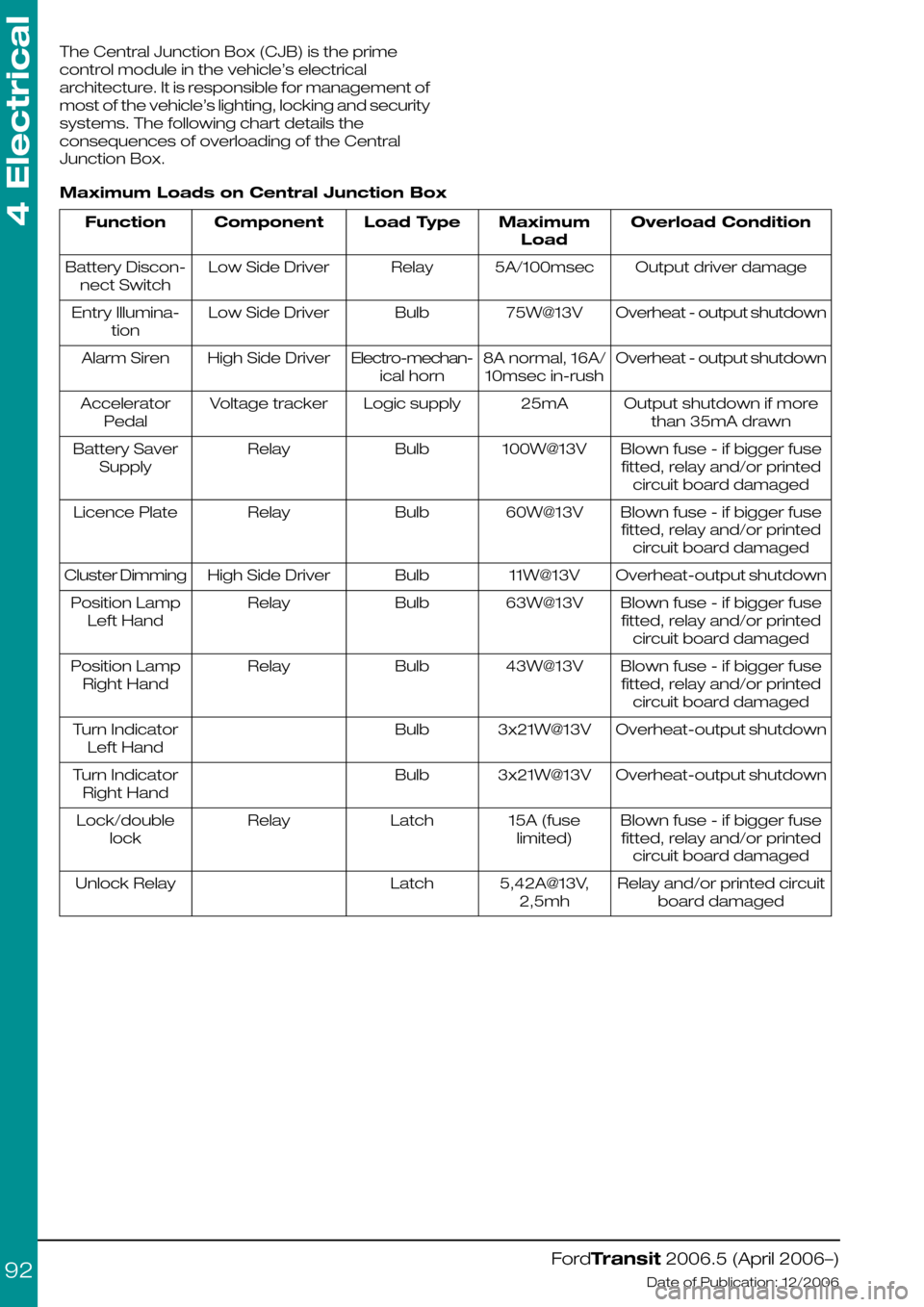
The Central Junction Box (CJB) is the prime
control module in the vehicle’s electrical
architecture. It is responsible for management of
most of the vehicle’s lighting, locking and security
systems. The following chart details the
consequences of overloading of the Central
Junction Box.
Maximum Loads on Central Junction Box
Overload ConditionMaximum
Load
Load TypeComponentFunction
Output driver damage5A/100msecRelayLow Side DriverBattery Discon-
nect Switch
Overheat - output shutdown75W@13VBulbLow Side DriverEntry Illumina-
tion
Overheat - output shutdown8A normal, 16A/
10msec in-rush
Electro-mechan-
ical horn
High Side DriverAlarm Siren
Output shutdown if more
than 35mA drawn
25mALogic supplyVoltage trackerAccelerator
Pedal
Blown fuse - if bigger fuse
fitted, relay and/or printed
circuit board damaged
100W@13VBulbRelayBattery Saver
Supply
Blown fuse - if bigger fuse
fitted, relay and/or printed
circuit board damaged
60W@13VBulbRelayLicence Plate
Overheat-output shutdown11W@13VBulbHigh Side DriverCluster Dimming
Blown fuse - if bigger fuse
fitted, relay and/or printed
circuit board damaged
63W@13VBulbRelayPosition Lamp
Left Hand
Blown fuse - if bigger fuse
fitted, relay and/or printed
circuit board damaged
43W@13VBulbRelayPosition Lamp
Right Hand
Overheat-output shutdown3x21W@13VBulbTurn Indicator
Left Hand
Overheat-output shutdown3x21W@13VBulbTurn Indicator
Right Hand
Blown fuse - if bigger fuse
fitted, relay and/or printed
circuit board damaged
15A (fuse
limited)
LatchRelayLock/double
lock
Relay and/or printed circuit
board damaged
5,42A@13V,
2,5mh
LatchUnlock Relay
FordTransit 2006.5 (April 2006–)
Date of Publication: 12/2006
4 Electrical
92
Page 106 of 234
4.5 Climate Control System
WARNING: Do not use propylene
glycol based coolant
•Never secure hoses or tubes to the
transmission fill or dip stick or to any fuel
system or brake component
•Do not route heater or refrigerant lines near or
directly over any exhaust system component,
including the exhaust manifolds.
•Avoid routing of hoses in the wheelhouse or
stone kick-up arch. However, if routing is
required in these areas, shield against stone
pecking as appropriate.
•Do not route hoses near sharp edges. Utilize
guards to protect against cutting or chafing.
FordTransit 2006.5 (April 2006–)
Date of Publication: 12/2006
4 Electrical
106
Page 131 of 234
4.14 Special Conversions
4.14.1 Vehicle Speed Output
(Signal)
At present, this information is only readily available
as a CAN message. However, on Diesel vehicles
it is possible to access a hard-wired output.
In the engine compartment there are three
connectors on the left hand side (viewed from
driving direction). On left hand drive vehicles, the
three connectors are covered with a plastic
shield that can be easily disassembled. On right
hand drive vehicles there is a special metal
security shield fixed with a shear bolt (part
number 6M5Y-12B539-A*). The vehicle speed
signal is available on pin K1 of the middle (brown)
connector, C2 – see Figure E84720 (Additional
Vehicle Signal / Features). This provides a square
wave-form (50% duty cycle) signal, where a
frequency of 138Hz equates to 100km/h.
Note:-
•A hard-wired vehicle speed signal is only
available on diesel engine vehicles.
•Vehicle speed is derived from one of two
sources, the wheel speed sensor (for vehicles
with ABS etc.) or the vehicle speed signal – in
both cases, these are un-calibrated signals.
According to transmission, drive-line and other
vehicle parameters that are set, the
Powertrain Control Module generates a CAN
message of vehicle speed for all vehicle types.
There is No hard-wired vehicle speed signal
on gasoline (petrol) vehicles.
•There is No automated shift transmission for
V4347/8 (there are no plans to introduce this
later in the program).
•VMT6 transmissions will not support fitment
of a vehicle speed sensor.
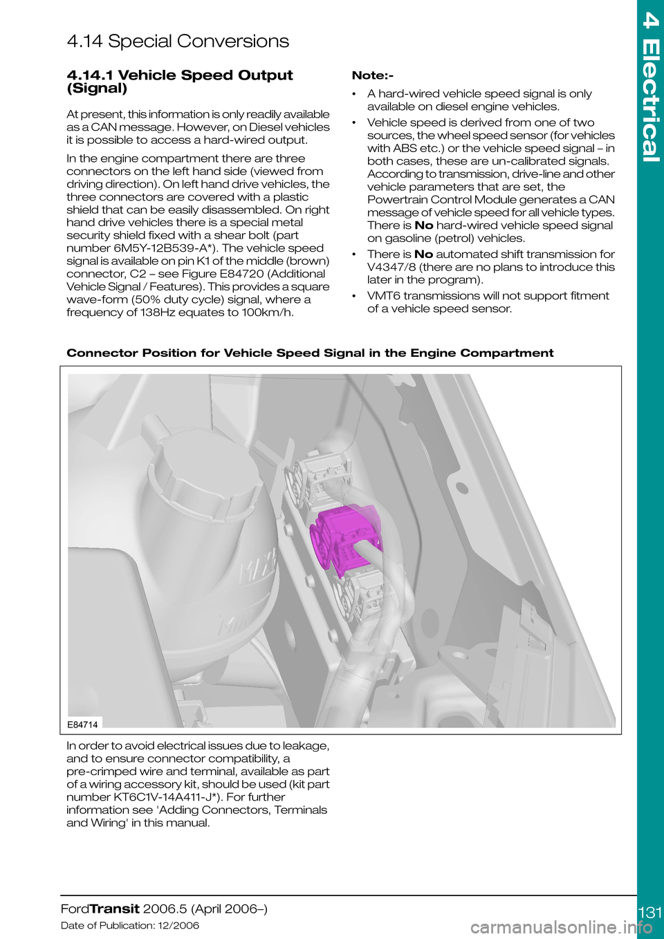
Connector Position for Vehicle Speed Signal in the Engine Compartment
In order to avoid electrical issues due to leakage,
and to ensure connector compatibility, a
pre-crimped wire and terminal, available as part
of a wiring accessory kit, should be used (kit part
number KT6C1V-14A411-J*). For further
information see 'Adding Connectors, Terminals
and Wiring' in this manual.
FordTransit 2006.5 (April 2006–)
Date of Publication: 12/2006
4 Electrical
131E84714
Page 154 of 234
harness that provides roof-mounted rear turn
indicators, powered via relays. This should be
used in conjunction with SVO fusebox.
3.Chassis cab LED rear lamp cluster
replacement recommendations, especially
turn indicator relay implications – see lighting
load table. Generally the use of LED equivalent
lighting systems reduces the electrical load on
the vehicle; however, special care needs to
be taken with respect to any change to or
addition of turn indicator lights. Depending on
the current requirements of the LED(s)
compared to the bulb it is replacing, a ballast
resistor may be required, if not already
integrated into the LED lamp assembly.
Without this, bulb outage detection for turn
indicators will be affected, which is a legal
requirement.
Additional turn indicators must be powered
through relays (max 300mA), driven by existing
turn lights. The maximum load that the Central
Junction Box can drive is 3 x 21W per side (front,
rear and CAT 6 turn indicators); but even if the
vehicle is not fitted with the CAT 6 lights, the feeds
for these should not be used as the Central
Junction Box would need reconfiguring, which
could have safety as well as functional
implications.
4.Special Vehicle Option beacon switch: wiring
locations, circuit diagrams and max amperage
– see Special Vehicle Option fuse box
schematic (max current is 15A); there is
provision for the Special Vehicle Option beacon
switch in an empty switch location on the
instrument panel.
5.Rear loom connector detail location and supply
details for retro-fit loom extension for
example:- when extending a medium wheel
base, long wheel base or extended frame
overhang, what connectors do they use to
make a plug and play loom extension? – for
chassis cab vehicles, there is an Special
Vehicle Option extension loom for rear lamps
(part number 6C1V-14408-A*). There is not, at
present, a similar loom for Van, Bus and
Kombi's, although the appropriate mating
connector is now tooled, so this would be
possible.
Miscellaneous Systems
Handbrake on - Cluster Warning Light -
Unless the vehicle is specified with options that
drive the handbrake warning light (for example
ESP, Australia market), the components making
up this system are not fitted. We do not
recommend installation of this feature as an
aftermarket addition. There are several reasons
for this:
1.Not all circuits carry the requisite wire as a give
away:
•The wires might be part of the main vehicle
harness (14401) even if not used – for example
camper vehicles are normally ordered with
power mirrors, and the wires will be present
as a give-away.
•The seat pedestal harness (14K076), however,
is vehicle specific – if the handbrake is not part
of the specification, it will not be present or
give-away. This harness would need to be
changed to the compatible part that also
includes the handbrake warning light circuit.
2.The handbrake switch (part number
2F2T-15852-A*) together with its short jumper
harness (6C1T-15K857-A*) would need to be
obtained and fitted.
3.The handbrake warning light is in all clusters,
but unless the vehicle config. parameter
“parking brake switch” is set, the Central
Junction Box will not read this input, and hence
NO CAN message sent to the cluster.
Reconfiguration can only be done at a Ford
Dealer.
NOTE: If a vehicle already has a handbrake
warning light in the cluster, or one is installed as
per the Ford design, it is not possible to utilize the
wire from the handbrake switch as part of an
interlock circuit (this is a pull up resistor input that
provides a wetting current of 20mA – anything in
excess of this, for example through additional
circuitry, will almost certainly damage the Central
Junction Box). If there is no handbrake switch
installed, it would be possible to add one and
utilize this as part of a separate circuit, up to a
maximum current of 500mA through the switch.
Reverse Sensors (Rear Park Aid
Module)- The factory-fit option is a CAN-based
system, but for Van, Bus, and Kombi vehicles
only. Stand-alone systems can be installed (for
example for chassis cab conversions), but would
need to utilize the PTA line of the radio if muting
is required.
Fuel Fired Heater (FFH)- Add FFH: wiring is
only present (give-away) in certain harnesses.
There was an aftermarket kit available for this
system on current Transit, which could probably
be “updated” to suit V347/8.
Fuel Fired Heater (FFH) - Programmable
FFH: this utilizes a timer/control module mounted
to the Instrument Panel, which necessitates
having the correct Instrument Panel harness
fitted. Retrofit of this would be a difficult.
For both systems, the appropriate 6C1T-14K132
harness would be required (suffix -A* for
Programmable FFH, and suffix –B* for Add FFH).
Central Locking
Locking is controlled by the Central Junction Box
module. There is current sensing on certain
locking circuit pins as part of the security system
– if these are tampered with, locking cannot be
guaranteed.
FordTransit 2006.5 (April 2006–)
Date of Publication: 12/2006
4 Electrical
154
Page 155 of 234
However, it is possible to add an additional lock(s)
– see also the section covering the ‘third button
on key fob’ – but only by utilizing relays (the
electric locks are operated by surface mounted
relays in the Central Junction Box – these are
only capable of powering one lock each, in
addition to which the output of these devices is
current-sensed to check it is within minimum and
maximum limits: I) to verify operation, and ii) as
part of the security system). For camper vehicles,
the Central Junction Box is configured for a
chassis cab vehicle.
Depending on functionality required, the pins
used will emulate the basic locking/unlocking
operation of an existing door. Note, however,
that any additional locks will not be covered by
the vehicle alarm or operate Central Junction
Box controlled lighting, etc. It would be necessary
to splice into either the Central Junction Box
connector or the in-line connector for the door
jumper harness. The coil of the relay (max.
300mA) should be added across the relevant
pin and ground (i.e. one relay for lock all, one
relay for driver door unlock etc.)
The use of Ford Transit lock mechanisms is
strongly recommended as the Central Junction
Box is designed to drive these latches for the
correct amount of time.
Function14A631 in-line
Passenger Side
14A631 in-line Drive
Side
Central Junc-
tion Box
Driver door unlock-6C2-7
Passenger door unlock (on
chassis Cab / Cab-Van Floor
only
6-C2-8
Deadlock all55C2-23
Lock all88C2-24
Locking Configurations- The following list
details specific locking scenarios that have been
noted by customers:
1.Raid locking or drive away locking for taxi and
parcel van usage – this is a configurable
parameter in the Central Junction Box (Ford
Dealerships can set this).
2.Slam locking – this is a configurable parameter
in Central Junction Box (marketing want to
sell this as an option, therefore dealerships
can only switch off this feature, but not switch
on).
3.N1 lock reconfiguration into M2 locking, i.e. no
deadlocks – this can be reconfigured to be
central-locking only by a Ford Dealer (via
Dealership hotline).
FordTransit 2006.5 (April 2006–)
Date of Publication: 12/2006
4 Electrical
155