suspension FORD TRANSIT 2006 7.G Body And Equipment Mounting Section Manual
[x] Cancel search | Manufacturer: FORD, Model Year: 2006, Model line: TRANSIT, Model: FORD TRANSIT 2006 7.GPages: 234, PDF Size: 33.19 MB
Page 3 of 234
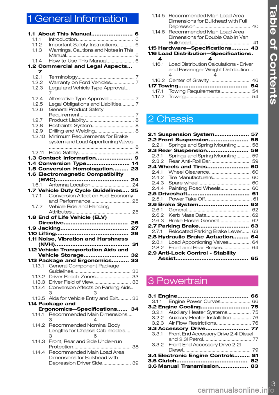
1 General Information
1.1About This Manual........................6
1.1.1Introduction...........................................6
1.1.2Important Safety Instructions.............6
1.1.3Warnings, Cautions and Notes in This
Manual....................................................6
1.1.4How to Use This Manual.....................6
1.2Commercial and Legal Aspects...
7
1.2.1Terminology...........................................7
1.2.2Warranty on Ford Vehicles..................7
1.2.3Legal and Vehicle Type Approval....
7
1.2.4Alternative Type Approval....................7
1.2.5Legal Obligations and Liabilities..........7
1.2.6General Product Safety
Requirement..........................................7
1.2.7Product Liability.....................................8
1.2.8Restraints System................................8
1.2.9Drilling and Welding..............................8
1.2.10Minimum Requirements for Brake
system and Load Apportioning Valves
.................................................................8
1.2.11Road Safety...........................................8
1.3Contact Information.....................9
1.4Conversion Type.........................14
1.5Conversion Homologation.........23
1.6Electromagnetic Compatibility
(EMC)..........................................24
1.6.1Antenna Location...............................24
1.7Vehicle Duty Cycle Guidelines....25
1.7.1Conversion Affect on Fuel Economy
and Performance...............................25
1.7.2Vehicle Ride and Handling
Attributes.............................................25
1.8End of Life Vehicle (ELV)
Directive.....................................26
1.9Jacking.......................................27
1.10Lifting..........................................29
1.11Noise, Vibration and Harshness
(NVH)...........................................31
1.12Vehicle Transportation Aids and
Vehicle Storage..........................32
1.13Package and Ergonomics..........33
1.13.1General Component Package
Guidelines............................................33
1.13.2Driver Reach Zones...........................33
1.13.3Driver Field of View.............................33
1.13.4Conversion Affects on Parking Aids..
33
1.13.5Aids for Vehicle Entry and Exit..........33
1.14Package and
Ergonomics—Specifications......34
1.14.1Recommended Main Dimensions....
34
1.14.2Recommended Nominal Body
Lengths for Chassis Cab models....
36
1.14.3Front, Rear and Side Under-run
Protection............................................38
1.14.4Recommended Main Load Area
Dimensions for Bulkhead with
Depression Driver Side......................39
1.14.5Recommended Main Load Area
Dimensions for Bulkhead with Full
Depression..........................................40
1.14.6Recommended Main Load Area
Dimensions for Double Cab In Van
Bulkhead..............................................41
1.15Hardware—Specifications..........43
1.16Load Distribution—Specifications.
44
1.16.1Load Distribution Calculations - Driver
and Passenger Weight Distribution...
44
1.16.2Center of Gravity ...............................46
1.17Towing........................................54
1.17.1Towing Requirements.......................54
1.17.2Towing..................................................54
2 Chassis
2.1Suspension System....................57
2.2Front Suspension.......................58
2.2.1Springs and Spring Mounting...........58
2.3Rear Suspension........................59
2.3.1Springs and Spring Mounting...........59
2.3.2Rear Anti-Roll Bar...............................59
2.4Wheels and Tires........................60
2.4.1Wheel Clearance................................60
2.4.2Tire Manufacturers.............................60
2.4.3Spare wheel........................................60
2.4.4Painting Road Wheels.......................60
2.5Driveshaft....................................61
2.5.1Power Take Off....................................61
2.6Brake System.............................62
2.6.1General................................................62
2.6.2Kerb Mass Data..................................62
2.6.3Brake Hoses General........................62
2.7Parking Brake.............................63
2.7.1Relocated Parking Brake Lever.......63
2.8Hydraulic Brake Actuation.........64
2.8.1Load Apportioning Valves.................64
2.8.2Front and Rear Brakes......................64
2.9Anti-Lock Control - Stability
Assist..........................................65
3 Powertrain
3.1Engine.........................................66
3.1.1Engine Power Curves.......................66
3.2Engine Cooling............................75
3.2.1Auxiliary Heater Systems..................75
3.2.2Auxiliary Heater Installation...............76
3.2.3Air Flow Restrictions...........................76
3.3Accessory Drive.........................77
3.3.1Front End Accessory Drive 2.4l Diesel
and 2.3l Petrol.....................................77
3.3.2Front End Accessory Drive 2.2l
Diesel....................................................79
3.4Electronic Engine Controls.........81
3.5Clutch.........................................82
3.6Manual Transmission.................83
Table of Contents
3
Page 33 of 234
1.13 Package and Ergonomics
1.13.1 General Component
Package Guidelines
WARNING: Do not modify, drill, cut
or weld any suspension
components, specifically the
steering gear system, subframe or
anti-roll bars, springs or shock
absorbers including mounting
brackets.
The Vehicle Converter has to ensure that
sufficient clearance is maintained under all drive
conditions to moving components such as axles,
fans, steering, brake system etc.
The Vehicle Converter is responsible for all
installed components during the conversion. The
durability has to be confirmed by appropriate test
procedures.
1.13.2 Driver Reach Zones
Controls and/or equipment required to be used
while driving should be located within easy reach
of the driver so as not to impair driver control
1.13.3 Driver Field of View
WARNING: Make sure that the
modified vehicle complies with all
relevant legal requirements.
1.13.4 Conversion Affects on
Parking Aids
WARNING: Ensure that monitors
mounted in the cabin meet the
interior package and safety
requirements
On conversions requiring a rear camera, the
reverse signal may be taken as described in the
electrical section, described in reversing lamps.
Refer to: 4.11 Exterior Lighting (page 116).
1.13.5 Aids for Vehicle Entry and
Exit
Steps
WARNINGS:
Make sure that the modified vehicle
complies with all relevant legal
requirements.
If this modification alters the
homologated dimensions, a new
approval may be necessary.
CAUTION: Make sure that
reinforcements are installed to
maintain the integrity of the original
body structure.
Steps can be ordered as an option on the base
vehicle. Please check for availability.
Where additional steps are installed the required
ground clearance line is to be maintained.
The Vehicle Converter must make sure that a
movable step is set in the stored position when
the vehicle is running. The step surface must be
non-slip.
Grab Handles
WARNING: Make sure that the
location of the no-drill zones are
checked before drilling.
CAUTION: Make sure that
reinforcements are installed to
maintain the integrity of the original
body structure.
Grab handles can be ordered as an option on
the base vehicle. Please check for availability.
NOTE: For further information please contact
your local National Sales Company
representative, or Local Ford Dealer. If they are
unable to help you then please contact the
Vehicle Converter Advisory Service at
[email protected].
FordTransit 2006.5 (April 2006–)
Date of Publication: 12/2006
1 General Information
33
Page 57 of 234
2.1 Suspension System
WARNING: Do not modify, drill, cut
or weld any suspension
components, specifically the
steering gear system, subframe or
anti-roll bars, springs or shock
absorbers including mounting
brackets.
CAUTION: Modifications to the
suspension system can cause a
deterioration of the vehicle handling
characteristics and durability.
NOTE: For detailed information please contact
the Vehicle Converter Advisory Service at
[email protected].
FordTransit 2006.5 (April 2006–)
Date of Publication: 12/2006
2 Chassis
57
Page 58 of 234
2.2 Front Suspension
2.2.1 Springs and Spring Mounting
WARNING: Do not modify, drill, cut
or weld any suspension
components, specifically the
steering gear system, subframe or
anti-roll bars, springs or shock
absorbers including mounting
brackets.
CAUTIONS:
When carrying out welding work the
springs must be covered to protect
them against weld splatter.
Do not touch springs with welding
electrodes or welding tongs.
Make sure that components
loosened or removed and reinstalled
are properly reassembled and the
torque set in accordance with
manufactures requirements.
NOTE: Do not modify the wheelbase or add any
type of frame extension to vehicles fitted with
Interactive Vehicle Dynamics (IVD)
NOTE: Do not damage the surface or corrosion
protection of the spring during disassembly and
installation.
NOTE: For detailed information please contact
the Vehicle Converter Advisory Service at
[email protected].
FordTransit 2006.5 (April 2006–)
Date of Publication: 12/2006
2 Chassis
58
Page 59 of 234
2.3 Rear Suspension
2.3.1 Springs and Spring
Mounting
WARNING: Do not modify, drill, cut
or weld any suspension
components, specifically the
steering gear system, sub-frame or
anti-roll bars, springs or shock
absorbers including mounting
brackets.
CAUTIONS:
When carrying out welding work the
springs must be covered to protect
them against weld splatter.
Do not touch springs with welding
electrodes or welding tongs.
Make sure that components
loosened or removed and reinstalled
are properly reassembled and the
torque set in accordance with
manufactures requirements.
NOTE: Do not modify the wheelbase or add any
type of frame extension to vehicles fitted with
Interactive Vehicle Dynamics (IVD)
NOTE: Do not damage the surface or corrosion
protection of the spring during disassembly and
installation.
NOTE: For detailed information please contact
the Vehicle Converter Advisory Service at
[email protected].
2.3.2 Rear Anti-Roll Bar
Remove the rear anti-roll bar on Chassis Cabs,
except on:
•330 and 350 Front Wheel Drive Chassis Cabs
with Box Body or with another conversion that
gives a similar or higher Centre of Gravity
(CoG) height.
•Dual Rear Wheel Chassis Cabs with Box Body
or with another conversion that gives a similar
or higher Centre of Gravity (CoG) height
FordTransit 2006.5 (April 2006–)
Date of Publication: 12/2006
2 Chassis
59
Page 60 of 234
2.4 Wheels and Tires
2.4.1 Wheel Clearance
The distance from the tire to the mudguard or
wheel arch must be sufficient, even if snow or
anti-skid chains are fitted and the suspension is
fully compressed allowing for axle twist as well.
Please consult the Vehicle Converter Advisory
Service [email protected] for clearance
requirements and data.
NOTE: Make sure that only approved wheels
and /or permissible tire sizes are fitted
For standard wheelhouse dimensions.
Refer to: 5.1 Body (page 175).
(Integral Bodies and Conversions)
2.4.2 Tire Manufacturers
Replacement tires should be of the same make,
size, tread pattern and load rating as the Original
Equipment Manufacturer. Under these conditions
the original tire label should be satisfactory,
however if the specified tires and/or inflation
pressures are changed then a new label should
be affixed over the original label.
2.4.3 Spare wheel
When converting or relocating the spare wheel,
access must be ensured.
2.4.4 Painting Road Wheels
CAUTION: Do not paint wheel clamp
surfaces in contact with other
wheels, brake drum or disc, hub and
holes, or surfaces under wheel nuts.
Any further treatment in these areas
may affect the wheel clamp
performance and the vehicle safety.
•Mask the wheel when changing the color or
repairing paint.
FordTransit 2006.5 (April 2006–)
Date of Publication: 12/2006
2 Chassis
60
Page 158 of 234
NOTE: A power take off layout can only be
implemented on vehicles fitted with an ABS
braking system. Manual braking systems employ
a transmission speed sensor to determine vehicle
speed & the RPM speed control software
contains vehicle speed restrictions which prohibit
RPM speed control operation if vehicle speed is
detected above very low levels (approx 2.5 mph).
A vehicle fitted with an ABS braking system
derives vehicle speed via the vehicles wheel
speed sensors, so the transmission can operate
normally without effecting RPM speed control
operation.
3 Modes of Operation
There are 3 principle modes in which this feature
can operate, they are:
1.3 speed mode – this provides the end user a
choice of up to 3 preset RPM values to select
from. The end user cannot easily override
these values so there is minimal risk of damage
to ancillary equipment due to it being run at
speeds it was not designed for. Very limited
vehicle speed is allowable while in this mode
(up to 2.5mph approx)
2.Variable speed mode – this provides the end
user with RPM speed ramp up & down
buttons. The end user is free to select RPM
values between 1300-3000rpm in 25rpm
steps. A single press results in a 25 rpm jump.
If a ramp button is held depressed by the end
user then the rate of change is 250rpm/sec.
Very limited vehicle speed is allowable while in
this mode (up to 2.5mph approx)
3.Idle up speed – this mode allows the engines
normal idle to be increased to any value (in 25
rpm steps) in the range 900-1200rpm. There
is not a vehicle speed restriction in this mode
as the intended use is to raise the engine idle
to reduce the likelihood of engine stall when
ancillary equipment is being run from the
engine during normal drive operations. Eg
refrigerator units used to keep the cargo bay
cool.
NOTE: Items 1) & 2) will be available from Nov
2006, while item 3) should be available from Jan
2007. Any latest generation diesel Transit can be
updated to include item 3) Idle up speed with a
simple calibration update once it becomes
available.
System Availability
This feature is built into the latest Powertrain
Control Module (PCM) software on all diesel
engine variants.
By default the feature is not enabled unless the
vehicle is specifically ordered with the feature
from the factory.
Vehicles which have not been ordered with this
feature may have the feature enabled at a dealer
via the IDS diagnostics system. The dealer should
charge for this service.
How to control this feature
A loop of wire (green/white) is provided in the
main electrical loom to permit control of the RPM
Speed Control software. Cutting this loop will
provide two wires to connect a control box to the
PCM.
The control box needs to switch resistors into the
circuit across the two green/white wires which
formally formed the loop prior to being cut. This
sort of circuit is known as a resistance ladder. The
PCM software monitors the green/white wire
circuit & when certain resistances are detected
they are interpreted as various inputs which
control the feature. The switch box can be
located where it’s ideally required for the vehicle
conversion in question, rather than having to be
mounted on the Instrument Panel (IP). If the
converter chooses to locate the switch box in a
location which is subject to an adverse
environment then the converter should design
the switch box to withstand with these conditions.
How to locate the green/white loop
The main electrical loom enters the vehicle cab
from the engine bay on the left hand side of the
vehicle via a large diameter hole in the engine bay
/ cabin bulkhead. This hole is just above the left
hand front suspension turret. See following Figure
E88307
FordTransit 2006.5 (April 2006–)
Date of Publication: 12/2006
4 Electrical
158
Page 230 of 234
A
About This Manual................................................6
Accessory Drive..................................................77
Adding Connectors, Terminals and Wiring....
162
Additional 'Theatre Lighting' for rear of vehicle
interior...............................................................118
Additional External Lamps...............................116
Additional Ignition, Instrument Panel Illumination
and Air Conditioning On Signals...................124
Additional Internal Lamps ................................118
Additional Vehicle Signals / Features.............147
Aids for Vehicle Entry and Exit..........................33
Air Bags..............................................................218
Air Bag Supplemental Restraint System (SRS)..
218
Air Flow Restrictions...........................................76
Alternative Type Approval....................................7
Ancillary Equipment - Sub Frame Mounting....
228
Antenna Location...............................................24
Anti-Lock Control - Stability Assist..................65
Auxiliary Fuses, Fuse Box and Relays (Fuses -
Standard)..........................................................119
Auxiliary Heater Installation...............................76
Auxiliary Heater Systems..................................75
B
Back Panel Removal................................177, 214
Battery and Cables............................................98
Battery Information............................................98
Body....................................................................175
Body Closures..................................................203
Body Structures - General Information.........175
Body System - General
Information—Specifications.........................200
Brake Hoses General........................................62
Brake System.....................................................62
C
Cab Roof Removal...........................................214
Cab Van Floor....................................................185
CAN-Bus System Description and Interface....
90
Cellular Phone....................................................115
Center of Gravity ...............................................46
Central Junction Box (CJB)...............................91
Charge Balance Guidelines..............................97
Charging System...............................................95
Chassis Cab.......................................................179
Circit Diagram.....................................................94
Circuit Diagram...................................................93
Circuit Diagrams.................................................97
Climate Control System..................................106
Clutch...................................................................82
Commercial and Legal Aspects.........................7
Communications Network...............................90
Connectors........................................................133
Contact Corrosion............................................221
Contact Information.............................................9
Conversion Affect on Fuel Economy and
Performance.....................................................25
Conversion Affects on Parking Aids................33
Conversion Homologation...............................23
Conversion Type.................................................14
Corrosion Prevention.......................................221
Customer Connection Points.........................120
D
Drilling and Welding..............................................8
Driver's Standing Head Room........................214
Driver Field of View.............................................33
Driver Reach Zones...........................................33
Driveshaft.............................................................61
E
Electrical Conversions.......................................95
Electrically operated Door Mirrors..................117
Electrics for Tow bar........................................136
Electromagnetic Compatibility (EMC)............24
Electronic Engine Controls................................81
End of Life Vehicle (ELV) Directive...................26
Engine Cooling....................................................75
Engine..................................................................66
Engine Power Curves.......................................66
Engine RPM (Revs Per Minute) Speed
Controller..........................................................157
Engine Run Signal (D+ Alternative)................132
Exhaust Heat Shields.........................................86
Exhaust Pipes and Supports............................86
Exhaust System.................................................86
Extended Chassis Frame...............................226
Extensions and Optional Exhausts..................86
Exterior Lighting.................................................116
F
Fitting of Equipment Containing an Electric
Motor..................................................................97
Frame and Body Mounting............................222
Frame Drilling and Tube Reinforcing.............228
Front, Rear and Side Under-run Protection....
38
Front and Rear Brakes......................................64
Front End Accessory Drive 2.2l Diesel............79
Front End Accessory Drive 2.4l Diesel and 2.3l
Petrol...................................................................77
Front End Integrity for Cooling, Crash,
Aerodynamics and Lighting..........................198
Front Suspension...............................................58
Fuel System........................................................88
Fuses and Relays..............................................119
G
General........................................................62, 221
General Component Package Guidelines.....33
General Information and Specific Warnings....
95
General........................................................62, 221
General Product Safety Requirement...............7
Index
230
Page 231 of 234
Generator and Alternator...............................103
Glass, Frames and Mechanisms...................211
Ground Points..................................................140
H
Hardware—Specifications...............................43
Heated Seats...................................................210
Heated Windshield and Heated Rear Window.
213
Horn...................................................................108
How to Use This Manual....................................6
Hydraulic Brake Actuation...............................64
Hydraulic Lifting Equipment for Van, Bus, Kombi
and Chassis Cab...........................................186
I
Important Safety Instructions............................6
Information and Entertainment System -
General Information—Specifications...........112
Installation and Routing Guides.....................134
Instrument Cluster...........................................107
Integrated Bodies and Conversions.............177
Interior Lighting.................................................118
Introduction..........................................................6
J
Jacking................................................................27
K
Kerb Mass Data.................................................62
L
Lamps for Wide Vehicles.................................117
Lamps – Front and Rear Fog Lights..............117
Lamps – Hazard / Direction Indication..........117
Legal and Vehicle Type Approval......................7
Legal Obligations and Liabilities.........................7
Legislation.........................................................109
Lifting...................................................................29
Load Apportioning Valves................................64
Load Compartment Interior Lining...............203
Load Distribution—Specifications...................44
Load Distribution Calculations - Driver and
Passenger Weight Distribution.....................44
M
Manual Transmission........................................83
Minimum Requirements for Brake system and
Load Apportioning Valves ...............................8
Mirrors for Wide Vehicles...............................208
Module Communications
Network—Specifications................................94
Mounting Points and Tubing.........................222
N
Noise, Vibration and Harshness (NVH)...........31
Non Standard Rear Chassis Frame Extension.
226
P
Package and Ergonomics—Specifications....
34
Package and Ergonomics...............................33
Painting Road Wheels..............................60, 221
Parking Brake....................................................63
Partitions (Bulkhead) - Driver and Front
Passenger(s) Protection on Van, Bus and
Kombi..............................................................192
Possible Accessories.......................................113
Power Management Settings.........................95
Power Take Off...................................................61
Product Liability....................................................8
R
Racking Systems.............................................194
Radio Connector..............................................112
Rear Anti-Roll Bar..............................................59
Rear Seat Fixings Positions - Kombi............209
Rear Suspension...............................................59
Rear View Mirrors...........................................208
Rear Windows..................................................211
Recommended Main Dimensions.................34
Recommended Main Load Area Dimensions
for Bulkhead with Depression Driver Side....
39
Recommended Main Load Area Dimensions
for Bulkhead with Full Depression................40
Recommended Main Load Area Dimensions
for Double Cab In Van Bulkhead...................41
Recommended Nominal Body Lengths for
Chassis Cab models......................................36
Relays and Switches.......................................127
Relocated Parking Brake Lever......................63
Repairing Damaged Paint..............................221
Restraints System...............................................8
Reversing Lamps.............................................116
Road Safety..........................................................8
Roof Opening Panel........................................214
Roof Racks.......................................................216
Roof Ventilation................................................215
S
Safety Belt System.........................................220
Seats.................................................................209
Security, Anti Theft and Locking System
Security ..........................................................203
Self-Supporting Body Structure...................224
Spare Tire Access and Mounting.................229
Spare wheel.......................................................60
Special Conversions........................................131
Special Vehicle Option Auxiliary Fuse Box....
121
Index
231
Page 232 of 234
Special Vehicle Options (SVO) and Aftermarket
Kits....................................................................146
Springs and Spring Mounting....................58, 59
Suspension System...........................................57
T
Tachograph Mounting......................................110
Tachograph.......................................................109
Tank and Dry Bulk Carriers..............................199
Terminology...........................................................7
Tipper Bodies....................................................199
Tire Manufacturers.............................................60
Towing Requirements.......................................54
Towing..................................................................54
U
Under Body Protection and Material.............221
V
Van Floor - Load Compartment Tie Downs for
Van ,Bus and Kombi......................................200
Vehicle Duty Cycle Guidelines..........................25
Vehicle Electrical Capacity - Alternator...........97
Vehicle Ride and Handling Attributes..............25
Vehicle Speed Output (Signal)........................131
Vehicle Transportation Aids and Vehicle
Storage..............................................................32
W
Warnings, Cautions and Notes in This Manual..
6
Warranty on Ford Vehicles..................................7
Wheel Clearance................................................60
Wheels and Tires................................................60
Windscreen wipers..........................................130
Wiring Specification...........................................119
Index
232