WIRING HARNESS FORD TRANSIT 2006 7.G Body And Equipment Mounting Section Manual
[x] Cancel search | Manufacturer: FORD, Model Year: 2006, Model line: TRANSIT, Model: FORD TRANSIT 2006 7.GPages: 234, PDF Size: 33.19 MB
Page 75 of 234
3.2 Engine Cooling
3.2.1 Auxiliary Heater Systems
WARNINGS:
Ford coolant additives are
necessary for the complete function
of the system. Only use ford
approved or equivalent specification
component, to withstand any
detrimental effects on the materials.
Do not mount components in front
of the grille or in an area of air flow
around the engine, which could
affect the engine cooling.
CAUTIONS:
Only make connections into the
heater hose between the front cab
heater and water pump return inlet.
Do not exceed the vehicle's original
coolant volume by more than 10%
Only use the manufactures
recommended (or equivalent
specification) coolant
additives/anti-freeze. Do not mix
coolant types.
•Coolant flow to cab heater must have priority
over flow to auxiliary heater or hand wash
facility.
•Coolant tube routing must be below the base
of the degas bottle.
•Use aluminum or plastic tee junction with
swaged or beaded ends to prevent hose blow
off. Reconnect original coolant tube as shown
in view E74570 (in this section) with standard
Ford water hose clip or suitable equivalent
specification clip. Ensure interference fit
between hose and 'T' joint.
•Tube routing must be secured to the body
structure or suitable brackets avoiding
electrical components or wires, hot or moving
parts and brake or fuel system components
•Hose must be heat sleeved with appropriate
material if within 100mm of exhaust
components (for example, manifold or
exhaust gas recirculating).
•The vertical clearance between the critical
cooling components (radiator, fan shroud and
radiator brackets) and both the hood inner
and outer (assembly) panels at design position
shall not be less than 15mm.
•There shall be a minimum clearance of 7mm
between the engine assembly and flexible
components (for example, hoses or wiring
harnesses) affixed to front end sheet metal
hardware, under a maximum engine torque
roll condition.
NOTE: For further information please contact
your local National Sales Company
representative, or Local Ford Dealer. If they are
unable to help you then please contact the
Vehicle Converter Advisory service at
[email protected].
FordTransit 2006.5 (April 2006–)
Date of Publication: 12/2006
3 Powertrain
75
Page 97 of 234
•Before disconnecting the battery, check
availability of radio key code.
•Fuses – when auxiliary electrical systems are
to be added to the vehicle it is mandatory that
the additional circuit design includes the
necessary fuses.
•The Special Vehicle Option auxiliary fuse box
is recommended.
Refer to: 4.13 Fuses and Relays (page 119).
4.3.4 Fitting of Equipment
Containing an Electric Motor
WARNINGS:
When equipment containing an
electrical motor is connected, it
must be connected via a blocking
diode or relay to prevent “back
Electro Motive Force (EMF)” being
applied to the auxiliary terminal.
When electric motors are to be
fitted, account must be taken of the
potentially high currents that a
motor can draw.
CAUTION: The following must be
observed:
•All motors must be driven via relays with
contacts rated at least 3 times the maximum
rated current of the motor.
•All motor supply circuits must be individually
fused with the proper fuse rating for the
motor.
•All power wiring must be rated for at least 3
times the rating of the motor and installed as
far away as possible from any existing vehicle
wiring.
•All motors fitted should be fully suppressed to
ensure electrical interference does not affect
the vehicle systems.
•Add EMC emissions statement to CE
approval.
4.3.5 Vehicle Electrical Capacity
- Alternator
WARNING: Do not cut into the
alternator wires or use the
alternator as a source to obtain a
'D+ Signal'
An engine run signal is available from the Central
Junction Box by installing a T-piece jumper
harness (Ford Part Number 6C1V-14A411-F_).
Refer to: 4.14 Special Conversions (page 131).
4.3.6 Charge Balance Guidelines
The base vehicle is fitted with a 150A alternator.
It is recommended to conduct a charge balance
calculation in case the conversion comprises a
high number of electrical consumers or high
electrical consumption is expected.
4.3.7 Circuit Diagrams
For circuit diagrams for Auxiliary Fuse Box
Connections and Standard Ford relays.
Refer to: 4.13 Fuses and Relays (page 119).
Full vehicle wiring and circuit diagrams are in the
Ford Workshop Manual.
NOTE: For further information please contact
your local National Sales Company
representative, or Local Ford Dealer. If they are
unable to help you then please contact the
Vehicle Converter Advisory Service at
[email protected].
FordTransit 2006.5 (April 2006–)
Date of Publication: 12/2006
4 Electrical
97
Page 100 of 234
Pull-in us actuvated within 70 ms of switching to
key position II
Pull-out is activated when switching to key
position I, or 0, and in key position II when no
engine run signal is sensed within 120 secs.
It is not possible to change state within 500 ms.
Removal of the Battery Disconnect
Switch (on twin battery models) and
wiring of batteries in parallel for high
current applications.
For vehicles equipped with a twin battery system,
wiring of the two batteries in parallel is not
recommended. If higher current is required,
680Ah batteries can be fitted (or a deep cycle
battery in lieu of the non-start relevant battery
only). Where a single passenger seat is fitted,
further batteries (1 or 2) can be installed in the
pedestal and added in parallel to the
non-start-relevant battery, although due
consideration then needs to be given to
increased current availability in the event of a
short circuit. Additional batteries should not be
installed under a passenger bench seat.
if this requirement is imperative, it would be
possible to disconnect the battery disconnect
switch and put the start-relevant and
non-start-relevant batteries in parallel using a
shorting bar (available from the Ford Delerships,
part number 6C1T-14A439-A*). There is one
important consideration when replacing the
battery disconnect switch with a shorting bar:
•Where the vehicle is configured for
twin-battery operation, the Central Junction
Box will detect if the battery disconnect switch
is missing (or has been removed), or the
mating connector short-circuited, and although
the vehicle will be functional, Diagnostic
Trouble Codes will be generated that will
flag-up during service. Hence if a shorting bar
is fitted, the vehicle needs to be reconfigured
(via the Dealership and Dealership Hotline).
Single to Dual Battery Conversion
For vehicles equipped with a single battery, it is
possible to upgrade to a twin battery system -
the connector for the battery disconnect switch
is present on all vehicles. In addition to
reconfiguring the vehicle for twin battery
operation (at a Dealership), the following battery
cables and components are required:
DescriptionPart Number
start relevant battery negative to vehicle ground point cable (right hand)
replaces C_ part
6C1T-14301-A_
start relevant battery negative to vehicle ground point cable (lefthand)
replaces D_ part
6C1T-14301-E_
start relevant battery negative to non-start relevant battery negative cable6C1T-14280-E_
pre-fuse box bus bar to non-start-relevant battery positive cable6C1T-14300-D_
Battery disconnect switch6C1T-10B728-A_
If a requirement exists (camper conversions for
example), it may be viable to order vehicles
installed with a single battery, a battery disconnect
switch, and a kit of harnesses – detailed above –
to be fitted by the installer.
Where required, e.g. for camper conversions,
gas-sealed battery boxes (with exterior venting)
are available. Ford part numbers:
6C1T-10N669-A_ (lefthand); 6C1T-10N669-B_
(right hand); 6C1T-10N725-A_ (lid).
The battery disconnect switch isolates the
auxiliary battery/batteries from the rest of the
base vehicle electrical system when the engine
is stopped.
The battery disconnect switch, together with
associated wiring and hardware, can be fitted as
part of an accessory kit (available from your local
Ford dealer) in the pre-fuse box.
FordTransit 2006.5 (April 2006–)
Date of Publication: 12/2006
4 Electrical
100
Page 110 of 234
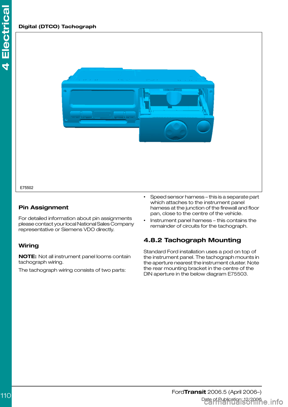
Digital (DTCO) Tachograph
Pin Assignment
For detailed information about pin assignments
please contact your local National Sales Company
representative or Siemens VDO directly.
Wiring
NOTE: Not all instrument panel looms contain
tachograph wiring.
The tachograph wiring consists of two parts:
•Speed sensor harness – this is a separate part
which attaches to the instrument panel
harness at the junction of the firewall and floor
pan, close to the centre of the vehicle.
•Instrument panel harness – this contains the
remainder of circuits for the tachograph.
4.8.2 Tachograph Mounting
Standard Ford installation uses a pod on top of
the instrument panel. The tachograph mounts in
the aperture nearest the instrument cluster. Note
the rear mounting bracket in the centre of the
DIN aperture in the below diagram E75503.
FordTransit 2006.5 (April 2006–)
Date of Publication: 12/2006
4 Electrical
110E75502
Page 113 of 234
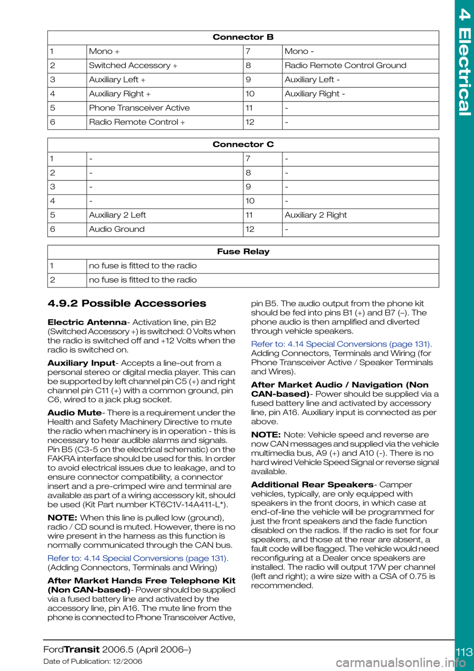
Connector B
Mono -7Mono +1
Radio Remote Control Ground8Switched Accessory +2
Auxiliary Left -9Auxiliary Left +3
Auxiliary Right -10Auxiliary Right +4
-11Phone Transceiver Active5
-12Radio Remote Control +6
Connector C
-7-1
-8-2
-9-3
-10-4
Auxiliary 2 Right11Auxiliary 2 Left5
-12Audio Ground6
Fuse Relay
no fuse is fitted to the radio1
no fuse is fitted to the radio2
4.9.2 Possible Accessories
Electric Antenna- Activation line, pin B2
(Switched Accessory +) is switched: 0 Volts when
the radio is switched off and +12 Volts when the
radio is switched on.
Auxiliary Input- Accepts a line-out from a
personal stereo or digital media player. This can
be supported by left channel pin C5 (+) and right
channel pin C11 (+) with a common ground, pin
C6, wired to a jack plug socket.
Audio Mute- There is a requirement under the
Health and Safety Machinery Directive to mute
the radio when machinery is in operation - this is
necessary to hear audible alarms and signals.
Pin B5 (C3-5 on the electrical schematic) on the
FAKRA interface should be used for this. In order
to avoid electrical issues due to leakage, and to
ensure connector compatibility, a connector
insert and a pre-crimped wire and terminal are
available as part of a wiring accessory kit, should
be used (Kit Part number KT6C1V-14A411-L*).
NOTE: When this line is pulled low (ground),
radio / CD sound is muted. However, there is no
wire present in the harness as this function is
normally communicated through the CAN bus.
Refer to: 4.14 Special Conversions (page 131).
(Adding Connectors, Terminals and Wiring)
After Market Hands Free Telephone Kit
(Non CAN-based)- Power should be supplied
via a fused battery line and activated by the
accessory line, pin A16. The mute line from the
phone is connected to Phone Transceiver Active,
pin B5. The audio output from the phone kit
should be fed into pins B1 (+) and B7 (–). The
phone audio is then amplified and diverted
through vehicle speakers.
Refer to: 4.14 Special Conversions (page 131).
Adding Connectors, Terminals and Wiring (for
Phone Transceiver Active / Speaker Terminals
and Wires).
After Market Audio / Navigation (Non
CAN-based)- Power should be supplied via a
fused battery line and activated by accessory
line, pin A16. Auxiliary input is connected as per
above.
NOTE: Note: Vehicle speed and reverse are
now CAN messages and supplied via the vehicle
multimedia bus, A9 (+) and A10 (-). There is no
hard wired Vehicle Speed Signal or reverse signal
available.
Additional Rear Speakers- Camper
vehicles, typically, are only equipped with
speakers in the front doors, in which case at
end-of-line the vehicle will be programmed for
just the front speakers and the fade function
disabled on the radios. If the radio is set for four
speakers, and those at the rear are absent, a
fault code will be flagged. The vehicle would need
reconfiguring at a Dealer once speakers are
installed. The radio will output 17W per channel
(left and right); a wire size with a CSA of 0.75 is
recommended.
FordTransit 2006.5 (April 2006–)
Date of Publication: 12/2006
4 Electrical
113
Page 114 of 234
Rear speaker wiring is always present in the
instrument panel harness (14K024), but not
necessarily in the harnesses (14401 and
14405/14A005) that then take the signals to the
rear speaker locations
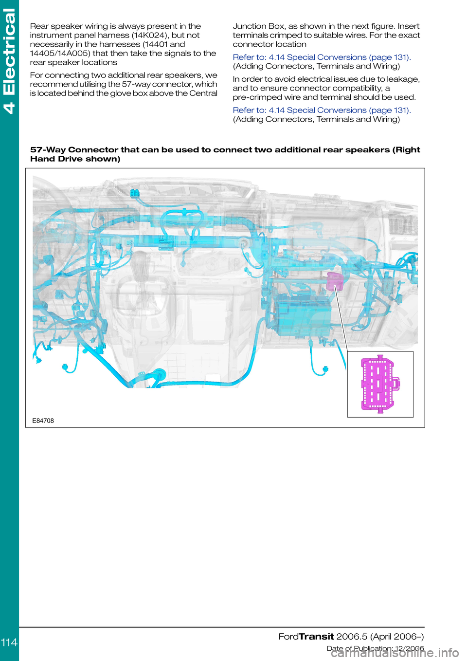
For connecting two additional rear speakers, we
recommend utilising the 57-way connector, which
is located behind the glove box above the Central
Junction Box, as shown in the next figure. Insert
terminals crimped to suitable wires. For the exact
connector location
Refer to: 4.14 Special Conversions (page 131).
(Adding Connectors, Terminals and Wiring)
In order to avoid electrical issues due to leakage,
and to ensure connector compatibility, a
pre-crimped wire and terminal should be used.
Refer to: 4.14 Special Conversions (page 131).
(Adding Connectors, Terminals and Wiring)
57-Way Connector that can be used to connect two additional rear speakers (Right
Hand Drive shown)
FordTransit 2006.5 (April 2006–)
Date of Publication: 12/2006
4 Electrical
114E84708
Page 125 of 234
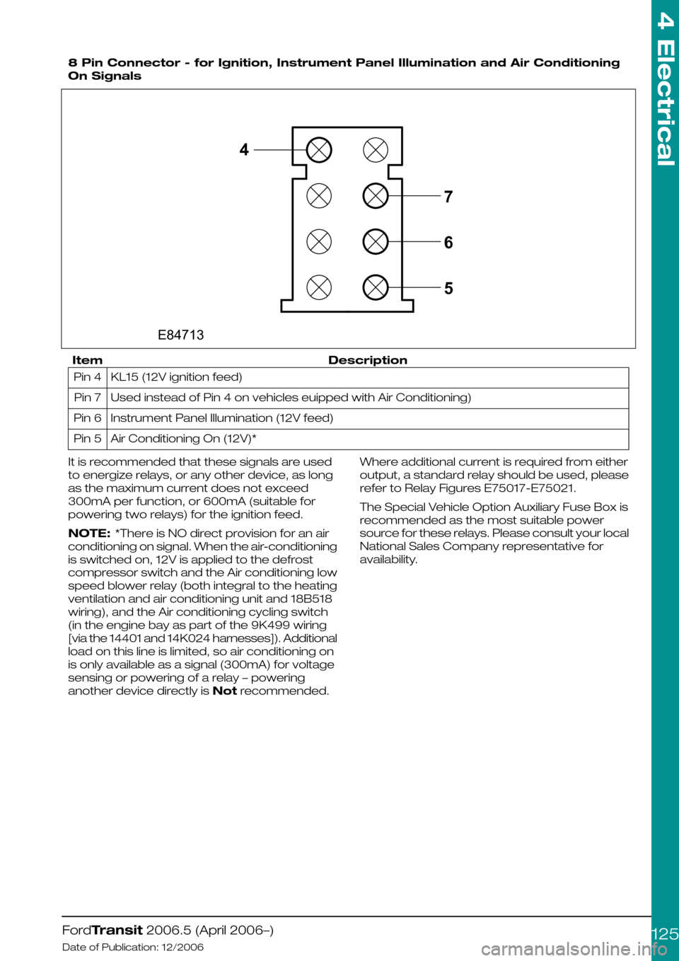
8 Pin Connector - for Ignition, Instrument Panel Illumination and Air Conditioning
On Signals
DescriptionItem
KL15 (12V ignition feed)Pin 4
Used instead of Pin 4 on vehicles euipped with Air Conditioning)Pin 7
Instrument Panel Illumination (12V feed)Pin 6
Air Conditioning On (12V)*Pin 5
It is recommended that these signals are used
to energize relays, or any other device, as long
as the maximum current does not exceed
300mA per function, or 600mA (suitable for
powering two relays) for the ignition feed.
NOTE: *There is NO direct provision for an air
conditioning on signal. When the air-conditioning
is switched on, 12V is applied to the defrost
compressor switch and the Air conditioning low
speed blower relay (both integral to the heating
ventilation and air conditioning unit and 18B518
wiring), and the Air conditioning cycling switch
(in the engine bay as part of the 9K499 wiring
[via the 14401 and 14K024 harnesses]). Additional
load on this line is limited, so air conditioning on
is only available as a signal (300mA) for voltage
sensing or powering of a relay – powering
another device directly is Not recommended.
Where additional current is required from either
output, a standard relay should be used, please
refer to Relay Figures E75017-E75021.
The Special Vehicle Option Auxiliary Fuse Box is
recommended as the most suitable power
source for these relays. Please consult your local
National Sales Company representative for
availability.
FordTransit 2006.5 (April 2006–)
Date of Publication: 12/2006
4 Electrical
1254E84713765
Page 133 of 234
The fitment of the Special Vehicle Option auxiliary
box will provide a power source for the relay
(although connection to the engine run pin is still
required).
Where connections are already made to the
engine run signal, it is vital that these connections
remain connected. In this instance, a suitable 'Y'
Jumper link should be used to tap out of the
connection.
Refer to: 4.13 Fuses and Relays (page 119).
If a positive (+12V) engine run signal is required,
this is possible by using the relay contacts to ‘pull
in’ 12V (preferably an ignition feed, KL15)
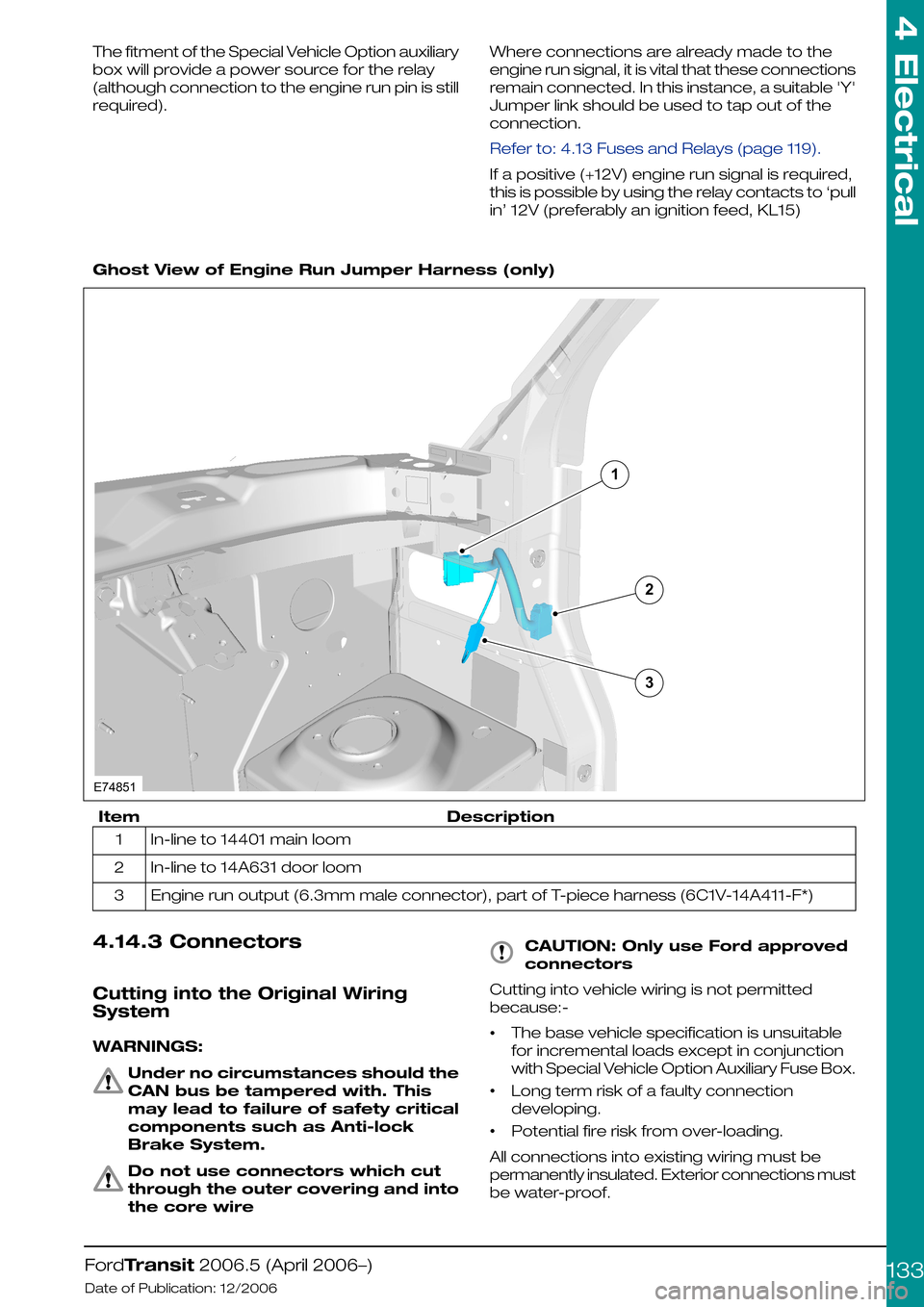
Ghost View of Engine Run Jumper Harness (only)
DescriptionItem
In-line to 14401 main loom1
In-line to 14A631 door loom2
Engine run output (6.3mm male connector), part of T-piece harness (6C1V-14A411-F*)3
4.14.3 Connectors
Cutting into the Original Wiring
System
WARNINGS:
Under no circumstances should the
CAN bus be tampered with. This
may lead to failure of safety critical
components such as Anti-lock
Brake System.
Do not use connectors which cut
through the outer covering and into
the core wire
CAUTION: Only use Ford approved
connectors
Cutting into vehicle wiring is not permitted
because:-
•The base vehicle specification is unsuitable
for incremental loads except in conjunction
with Special Vehicle Option Auxiliary Fuse Box.
•Long term risk of a faulty connection
developing.
•Potential fire risk from over-loading.
All connections into existing wiring must be
permanently insulated. Exterior connections must
be water-proof.
FordTransit 2006.5 (April 2006–)
Date of Publication: 12/2006
4 Electrical
133132E74851
Page 134 of 234
Where wires are required to be extended, break
in points should only be at existing connector
points and only Ford approved connectors should
be used.
Ford approved link harnesses should be used.
Unused Connectors
The harnesses may have a number of unused
connectors – these are dedicated to other
features and options, e.g. heated seats, but are
not always present depending on level of
harness fitted. Ford do not recommend the use
of these connectors for any other purpose than
that intended by design.
Power Outlet / Cigar Lighter
Both features adopt a 20A fusing strategy. With
a single battery system, continued loading of
these features will lead to battery drain, and risk
vehicle starting. If continuous power is required,
a second battery option should be installed and
the customer connection points, where fitted,
utilized.
4.14.4 Installation and Routing Guides
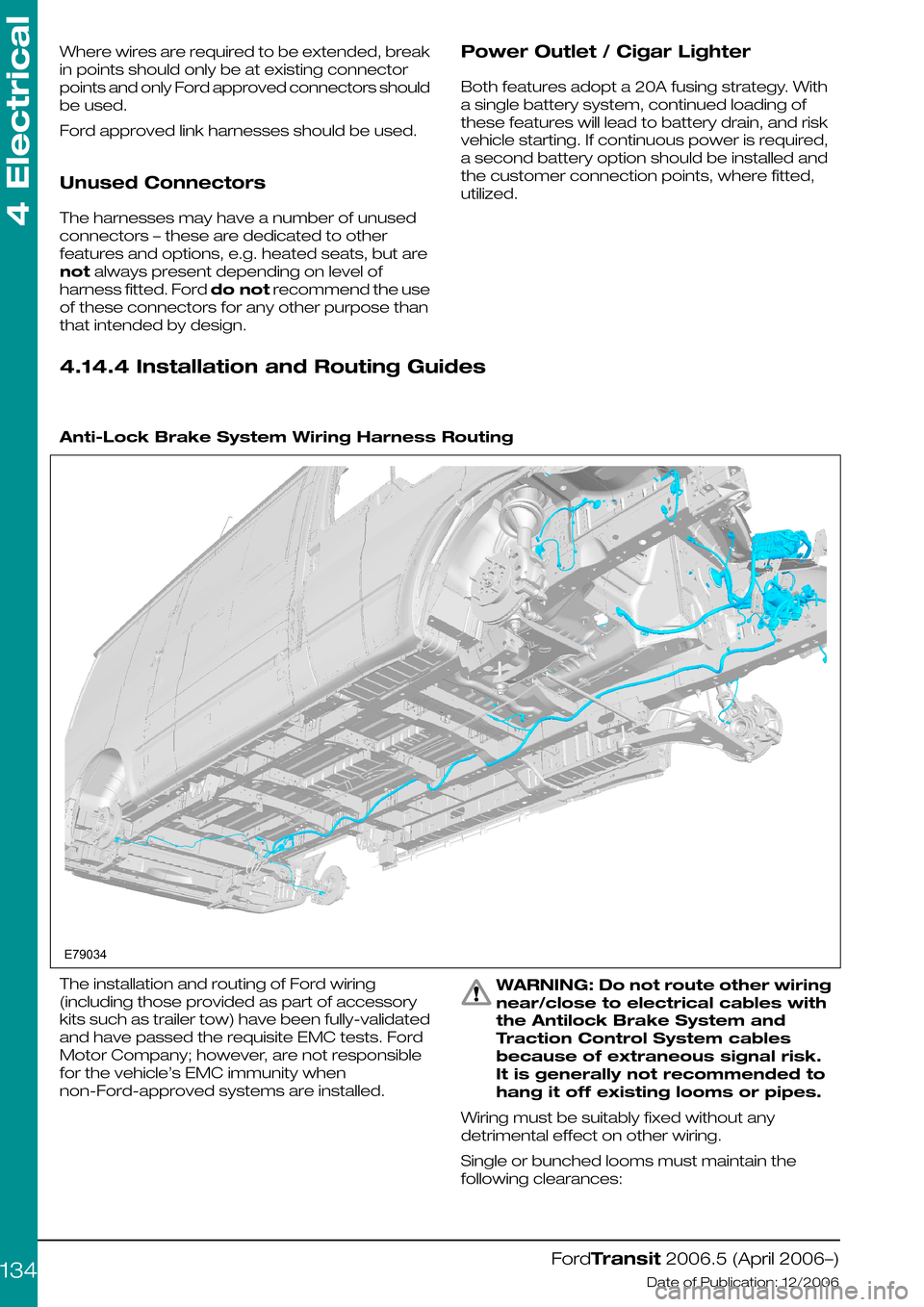
Anti-Lock Brake System Wiring Harness Routing
The installation and routing of Ford wiring
(including those provided as part of accessory
kits such as trailer tow) have been fully-validated
and have passed the requisite EMC tests. Ford
Motor Company; however, are not responsible
for the vehicle’s EMC immunity when
non-Ford-approved systems are installed.
WARNING: Do not route other wiring
near/close to electrical cables with
the Antilock Brake System and
Traction Control System cables
because of extraneous signal risk.
It is generally not recommended to
hang it off existing looms or pipes.
Wiring must be suitably fixed without any
detrimental effect on other wiring.
Single or bunched looms must maintain the
following clearances:
FordTransit 2006.5 (April 2006–)
Date of Publication: 12/2006
4 Electrical
134E79034
Page 136 of 234
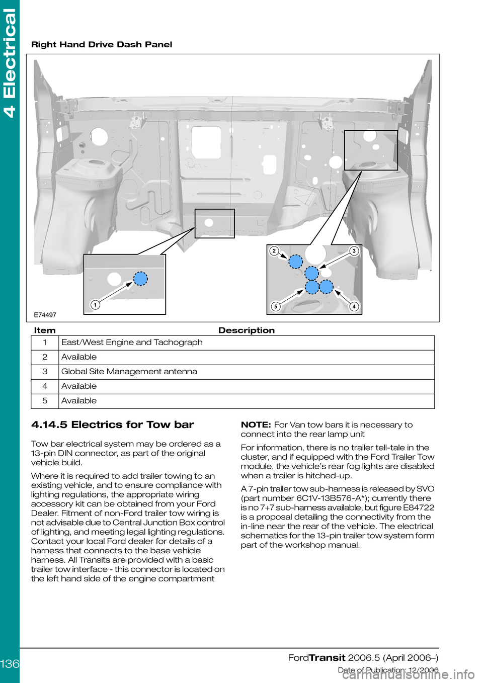
Right Hand Drive Dash Panel
DescriptionItem
East/West Engine and Tachograph1
Available2
Global Site Management antenna3
Available4
Available5
4.14.5 Electrics for Tow bar
Tow bar electrical system may be ordered as a
13-pin DIN connector, as part of the original
vehicle build.
Where it is required to add trailer towing to an
existing vehicle, and to ensure compliance with
lighting regulations, the appropriate wiring
accessory kit can be obtained from your Ford
Dealer. Fitment of non-Ford trailer tow wiring is
not advisable due to Central Junction Box control
of lighting, and meeting legal lighting regulations.
Contact your local Ford dealer for details of a
harness that connects to the base vehicle
harness. All Transits are provided with a basic
trailer tow interface - this connector is located on
the left hand side of the engine compartment
NOTE: For Van tow bars it is necessary to
connect into the rear lamp unit
For information, there is no trailer tell-tale in the
cluster, and if equipped with the Ford Trailer Tow
module, the vehicle’s rear fog lights are disabled
when a trailer is hitched-up.
A 7-pin trailer tow sub-harness is released by SVO
(part number 6C1V-13B576-A*); currently there
is no 7+7 sub-harness available, but figure E84722
is a proposal detailing the connectivity from the
in-line near the rear of the vehicle. The electrical
schematics for the 13-pin trailer tow system form
part of the workshop manual.
FordTransit 2006.5 (April 2006–)
Date of Publication: 12/2006
4 Electrical
136E7449724513