diagram FORD TRANSIT 2006 7.G Body And Equipment Mounting Section Manual
[x] Cancel search | Manufacturer: FORD, Model Year: 2006, Model line: TRANSIT, Model: FORD TRANSIT 2006 7.GPages: 234, PDF Size: 33.19 MB
Page 4 of 234
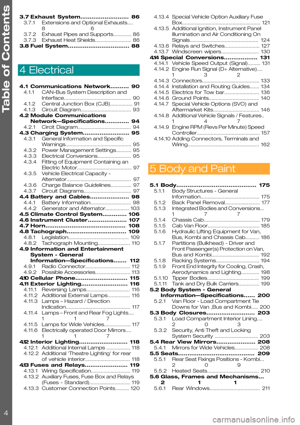
3.7Exhaust System..........................86
3.7.1Extensions and Optional Exhausts....
86
3.7.2Exhaust Pipes and Supports.............86
3.7.3Exhaust Heat Shields..........................86
3.8Fuel System.................................88
4 Electrical
4.1Communications Network..........90
4.1.1CAN-Bus System Description and
Interface................................................90
4.1.2Central Junction Box (CJB)................91
4.1.3Circuit Diagram....................................93
4.2Module Communications
Network—Specifications.............94
4.2.1Circit Diagram......................................94
4.3Charging System.........................95
4.3.1General Information and Specific
Warnings...............................................95
4.3.2Power Management Settings...........95
4.3.3Electrical Conversions........................95
4.3.4Fitting of Equipment Containing an
Electric Motor.......................................97
4.3.5Vehicle Electrical Capacity -
Alternator..............................................97
4.3.6Charge Balance Guidelines...............97
4.3.7Circuit Diagrams..................................97
4.4Battery and Cables.....................98
4.4.1Battery Information.............................98
4.4.2Generator and Alternator.................103
4.5Climate Control System.............106
4.6Instrument Cluster.....................107
4.7Horn...........................................108
4.8Tachograph................................109
4.8.1Legislation...........................................109
4.8.2Tachograph Mounting.......................110
4.9Information and Entertainment
System - General
Information—Specifications.......112
4.9.1Radio Connector................................112
4.9.2Possible Accessories.........................113
4.10Cellular Phone............................115
4.11Exterior Lighting.........................116
4.11.1Reversing Lamps...............................116
4.11.2Additional External Lamps................116
4.11.3Lamps – Hazard / Direction
Indication..............................................117
4.11.4Lamps – Front and Rear Fog Lights....
117
4.11.5Lamps for Wide Vehicles...................117
4.11.6Electrically operated Door Mirrors....
117
4.12Interior Lighting..........................118
4.12.1Additional Internal Lamps .................118
4.12.2Additional 'Theatre Lighting' for rear
of vehicle interior................................118
4.13Fuses and Relays.......................119
4.13.1Wiring Specification............................119
4.13.2Auxiliary Fuses, Fuse Box and Relays
(Fuses - Standard).............................119
4.13.3Customer Connection Points..........120
4.13.4Special Vehicle Option Auxiliary Fuse
Box........................................................121
4.13.5Additional Ignition, Instrument Panel
Illumination and Air Conditioning On
Signals.................................................124
4.13.6Relays and Switches.........................127
4.13.7Windscreen wipers...........................130
4.14Special Conversions..................131
4.14.1Vehicle Speed Output (Signal).........131
4.14.2Engine Run Signal (D+ Alternative)....
132
4.14.3Connectors.........................................133
4.14.4Installation and Routing Guides.......134
4.14.5Electrics for Tow bar.........................136
4.14.6Ground Points....................................140
4.14.7Special Vehicle Options (SVO) and
Aftermarket Kits.................................146
4.14.8Additional Vehicle Signals / Features..
147
4.14.9Engine RPM (Revs Per Minute) Speed
Controller.............................................157
4.14.10Adding Connectors, Terminals and
Wiring...................................................162
5 Body and Paint
5.1Body...........................................175
5.1.1Body Structures - General
Information..........................................175
5.1.2Back Panel Removal.........................177
5.1.3Integrated Bodies and Conversions...
177
5.1.4Chassis Cab........................................179
5.1.5Cab Van Floor.....................................185
5.1.6Hydraulic Lifting Equipment for Van,
Bus, Kombi and Chassis Cab..........186
5.1.7Partitions (Bulkhead) - Driver and
Front Passenger(s) Protection on Van,
Bus and Kombi..................................192
5.1.8Racking Systems...............................194
5.1.9Front End Integrity for Cooling, Crash,
Aerodynamics and Lighting.............198
5.1.10Tipper Bodies.....................................199
5.1.11Tank and Dry Bulk Carriers...............199
5.2Body System - General
Information—Specifications......200
5.2.1Van Floor - Load Compartment Tie
Downs for Van ,Bus and Kombi.....200
5.3Body Closures..........................203
5.3.1Load Compartment Interior Lining....
203
5.3.2Security, Anti Theft and Locking
System Security ...............................203
5.4Rear View Mirrors.....................208
5.4.1Mirrors for Wide Vehicles.................208
5.5Seats.........................................209
5.5.1Rear Seat Fixings Positions - Kombi...
209
5.5.2Heated Seats.....................................210
5.6Glass, Frames and Mechanisms...
211
5.6.1Rear Windows....................................211
Table of Contents
4
Page 54 of 234

1.17 Towing
1.17.1 Towing Requirements
When a towing device is required, the Vehicle
Converter should use a Ford approved tow bar.
Refer to: 1.16 (page 44).
Refer to: 1.9 Jacking (page 27).
1.17.2 Towing
For towing devices fitted by the Vehicle Converter
the following applies:
•Towing allowances must not exceed those of
the standard vehicle.
•For attachment of the tow bar, underrun bar
and step see the following diagrams
–E74854 Tow Bar Chassis Cab
–E74855 Tow Bar Van, Bus and Kombi.
Use the upper position to fix the tow ball on front
wheel drive vehicles and the lower position to fix
on rear wheel drive vehicles.
•Any modifications to the vehicle must be noted
in the owner's handbook or new descriptive
literature included with the owner's
documentation.
•The maximum allowable tow ball static load is
120kg on a Van, Bus and Kombi and 150kg on
Chassis Cabs.
•Tow bar installations must meet the
requirements of the EEC Directive 94/20 EC
Tow Bar Chassis Cab
FordTransit 2006.5 (April 2006–)
Date of Publication: 12/2006
1 General Information
54E74854
Page 93 of 234
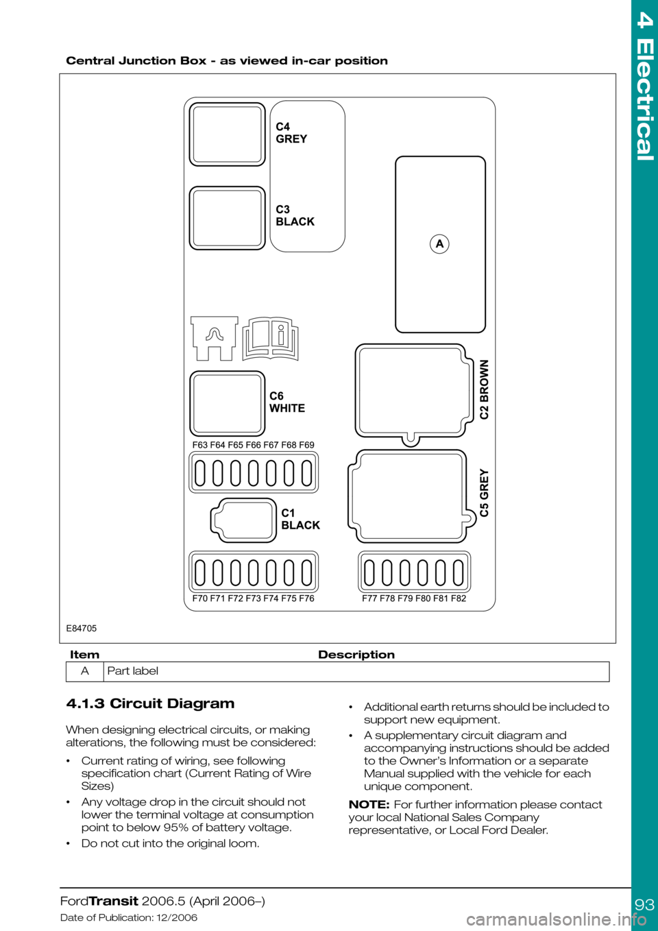
Central Junction Box - as viewed in-car position
DescriptionItem
Part labelA
4.1.3 Circuit Diagram
When designing electrical circuits, or making
alterations, the following must be considered:
•Current rating of wiring, see following
specification chart (Current Rating of Wire
Sizes)
•Any voltage drop in the circuit should not
lower the terminal voltage at consumption
point to below 95% of battery voltage.
•Do not cut into the original loom.
•Additional earth returns should be included to
support new equipment.
•A supplementary circuit diagram and
accompanying instructions should be added
to the Owner’s Information or a separate
Manual supplied with the vehicle for each
unique component.
NOTE: For further information please contact
your local National Sales Company
representative, or Local Ford Dealer.
FordTransit 2006.5 (April 2006–)
Date of Publication: 12/2006
4 Electrical
93E84705
Page 94 of 234
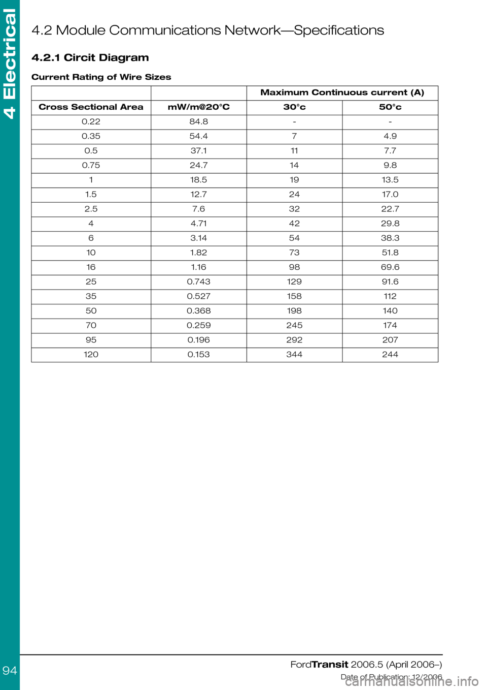
4.2 Module Communications Network—Specifications
4.2.1 Circit Diagram
Current Rating of Wire Sizes
Maximum Continuous current (A)
50°c30°cmW/m@20°CCross Sectional Area
--84.80.22
4.9754.40.35
7.71137.10.5
9.81424.70.75
13.51918.51
17.02412.71.5
22.7327.62.5
29.8424.714
38.3543.146
51.8731.8210
69.6981.1616
91.61290.74325
1121580.52735
1401980.36850
1742450.25970
2072920.19695
2443440.153120
FordTransit 2006.5 (April 2006–)
Date of Publication: 12/2006
4 Electrical
94
Page 97 of 234
•Before disconnecting the battery, check
availability of radio key code.
•Fuses – when auxiliary electrical systems are
to be added to the vehicle it is mandatory that
the additional circuit design includes the
necessary fuses.
•The Special Vehicle Option auxiliary fuse box
is recommended.
Refer to: 4.13 Fuses and Relays (page 119).
4.3.4 Fitting of Equipment
Containing an Electric Motor
WARNINGS:
When equipment containing an
electrical motor is connected, it
must be connected via a blocking
diode or relay to prevent “back
Electro Motive Force (EMF)” being
applied to the auxiliary terminal.
When electric motors are to be
fitted, account must be taken of the
potentially high currents that a
motor can draw.
CAUTION: The following must be
observed:
•All motors must be driven via relays with
contacts rated at least 3 times the maximum
rated current of the motor.
•All motor supply circuits must be individually
fused with the proper fuse rating for the
motor.
•All power wiring must be rated for at least 3
times the rating of the motor and installed as
far away as possible from any existing vehicle
wiring.
•All motors fitted should be fully suppressed to
ensure electrical interference does not affect
the vehicle systems.
•Add EMC emissions statement to CE
approval.
4.3.5 Vehicle Electrical Capacity
- Alternator
WARNING: Do not cut into the
alternator wires or use the
alternator as a source to obtain a
'D+ Signal'
An engine run signal is available from the Central
Junction Box by installing a T-piece jumper
harness (Ford Part Number 6C1V-14A411-F_).
Refer to: 4.14 Special Conversions (page 131).
4.3.6 Charge Balance Guidelines
The base vehicle is fitted with a 150A alternator.
It is recommended to conduct a charge balance
calculation in case the conversion comprises a
high number of electrical consumers or high
electrical consumption is expected.
4.3.7 Circuit Diagrams
For circuit diagrams for Auxiliary Fuse Box
Connections and Standard Ford relays.
Refer to: 4.13 Fuses and Relays (page 119).
Full vehicle wiring and circuit diagrams are in the
Ford Workshop Manual.
NOTE: For further information please contact
your local National Sales Company
representative, or Local Ford Dealer. If they are
unable to help you then please contact the
Vehicle Converter Advisory Service at
[email protected].
FordTransit 2006.5 (April 2006–)
Date of Publication: 12/2006
4 Electrical
97
Page 98 of 234
4.4 Battery and Cables
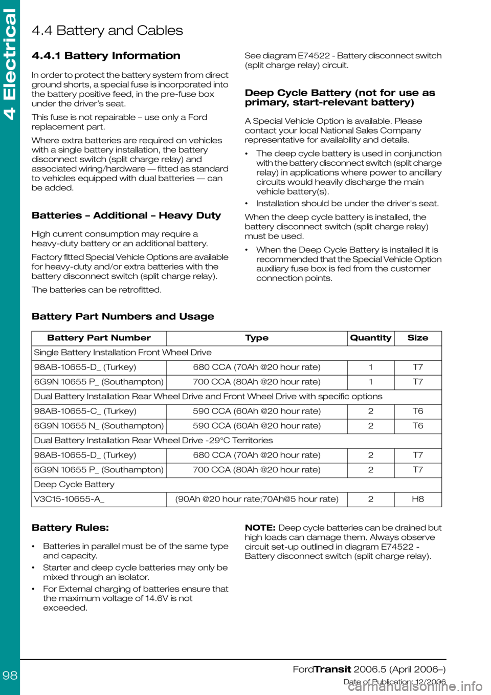
4.4.1 Battery Information
In order to protect the battery system from direct
ground shorts, a special fuse is incorporated into
the battery positive feed, in the pre-fuse box
under the driver’s seat.
This fuse is not repairable – use only a Ford
replacement part.
Where extra batteries are required on vehicles
with a single battery installation, the battery
disconnect switch (split charge relay) and
associated wiring/hardware — fitted as standard
to vehicles equipped with dual batteries — can
be added.
Batteries – Additional – Heavy Duty
High current consumption may require a
heavy-duty battery or an additional battery.
Factory fitted Special Vehicle Options are available
for heavy-duty and/or extra batteries with the
battery disconnect switch (split charge relay).
The batteries can be retrofitted.
See diagram E74522 - Battery disconnect switch
(split charge relay) circuit.
Deep Cycle Battery (not for use as
primary, start-relevant battery)
A Special Vehicle Option is available. Please
contact your local National Sales Company
representative for availability and details.
•The deep cycle battery is used in conjunction
with the battery disconnect switch (split charge
relay) in applications where power to ancillary
circuits would heavily discharge the main
vehicle battery(s).
•Installation should be under the driver's seat.
When the deep cycle battery is installed, the
battery disconnect switch (split charge relay)
must be used.
•When the Deep Cycle Battery is installed it is
recommended that the Special Vehicle Option
auxiliary fuse box is fed from the customer
connection points.
Battery Part Numbers and Usage
SizeQuantityTypeBattery Part Number
Single Battery Installation Front Wheel Drive
T71680 CCA (70Ah @20 hour rate)98AB-10655-D_ (Turkey)
T71700 CCA (80Ah @20 hour rate)6G9N 10655 P_ (Southampton)
Dual Battery Installation Rear Wheel Drive and Front Wheel Drive with specific options
T62590 CCA (60Ah @20 hour rate)98AB-10655-C_ (Turkey)
T62590 CCA (60Ah @20 hour rate)6G9N 10655 N_ (Southampton)
Dual Battery Installation Rear Wheel Drive -29°C Territories
T72680 CCA (70Ah @20 hour rate)98AB-10655-D_ (Turkey)
T72700 CCA (80Ah @20 hour rate)6G9N 10655 P_ (Southampton)
Deep Cycle Battery
H82(90Ah @20 hour rate;70Ah@5 hour rate)V3C15-10655-A_
Battery Rules:
•Batteries in parallel must be of the same type
and capacity.
•Starter and deep cycle batteries may only be
mixed through an isolator.
•For External charging of batteries ensure that
the maximum voltage of 14.6V is not
exceeded.
NOTE: Deep cycle batteries can be drained but
high loads can damage them. Always observe
circuit set-up outlined in diagram E74522 -
Battery disconnect switch (split charge relay).
FordTransit 2006.5 (April 2006–)
Date of Publication: 12/2006
4 Electrical
98
Page 103 of 234

4.4.2 Generator and Alternator
Torque Curve of Alternator
Diagram E75871 shows the torque in Nm which
is required to drive the alternator. The vertical
axis (A) shows the torque [Nm] and the horizontal
axis (B) shows the alternators revolutions per
minute [1/min].
NOTE: For equivalent engine revs per minute
(RPM), the alternators revolutions, axis (B) should
be divided by the following factors: 2.66 for diesel
(2.2L and 2.4L), 2.4 for Gasoline (2.3L).
NOTE: These alternator curves do not show
spare output capacity as this would be
dependant on original vehicle features and
options
FordTransit 2006.5 (April 2006–)
Date of Publication: 12/2006
4 Electrical
1030246810121402000400060008000100001200014000160001800020000ABE75871
Page 104 of 234

Current in relation to revolutions per minute
Diagram E75872 shows the current (A) in relation
to alternators revolutions (B) per minute [1/min].
This preliminary Bosch performance curve (1)
arose at a temperature of 25°C and a voltage of
13,5V.
FordTransit 2006.5 (April 2006–)
Date of Publication: 12/2006
4 Electrical
1040204060801001201401601800200040006000800010000120001400016000A1BE75872
Page 105 of 234
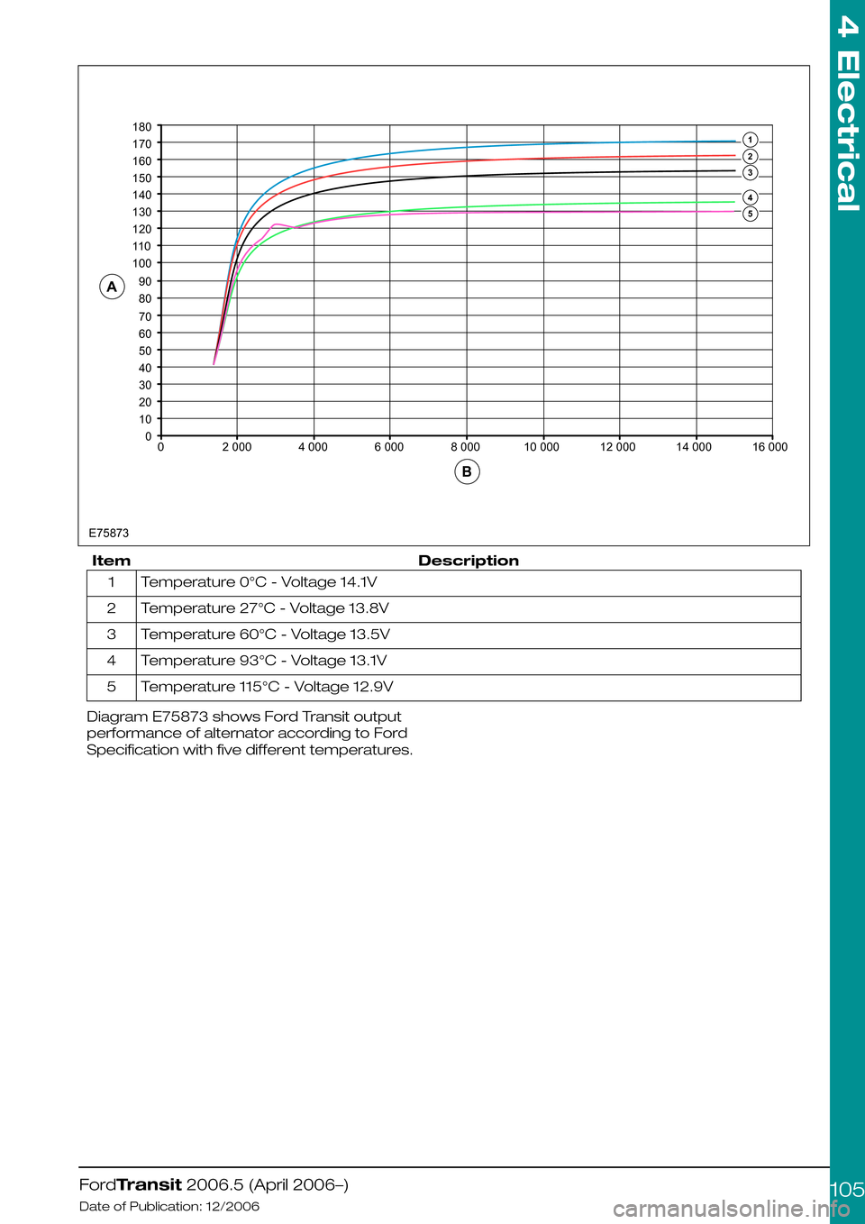
DescriptionItem
Temperature 0°C - Voltage 14.1V1
Temperature 27°C - Voltage 13.8V2
Temperature 60°C - Voltage 13.5V3
Temperature 93°C - Voltage 13.1V4
Temperature 115°C - Voltage 12.9V5
Diagram E75873 shows Ford Transit output
performance of alternator according to Ford
Specification with five different temperatures.
FordTransit 2006.5 (April 2006–)
Date of Publication: 12/2006
4 Electrical
105001020304050607080901001101201301401501601701802000E7587340006000800010000120001400016000AB54321
Page 109 of 234
4.8 Tachograph
The factory-fit Tachograph option uses a
Siemens VDO system. It is recommended,
therefore, that any vehicle that requires a
tachograph is sent to an authorised Siemens
VDO Tachograph Service Centre for system
installation and calibration.
Details of all recommended Service Centers can
be found on Siemens web site. This site also
contains details of current regulations and
tachograph operation.
4.8.1 Legislation
WARNING: All tachographs require
the same wiring connections as this
is controlled by tachograph
legislation.
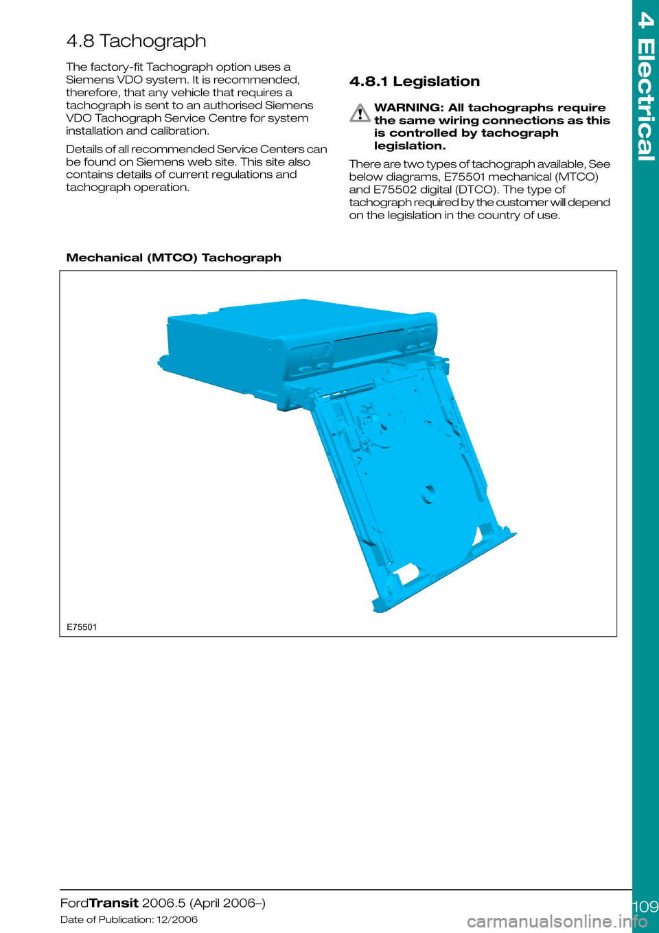
There are two types of tachograph available, See
below diagrams, E75501 mechanical (MTCO)
and E75502 digital (DTCO). The type of
tachograph required by the customer will depend
on the legislation in the country of use.
Mechanical (MTCO) Tachograph
FordTransit 2006.5 (April 2006–)
Date of Publication: 12/2006
4 Electrical
109E75501