height FORD TRANSIT 2006 7.G Body And Equipment Mounting Section Manual
[x] Cancel search | Manufacturer: FORD, Model Year: 2006, Model line: TRANSIT, Model: FORD TRANSIT 2006 7.GPages: 234, PDF Size: 33.19 MB
Page 36 of 234
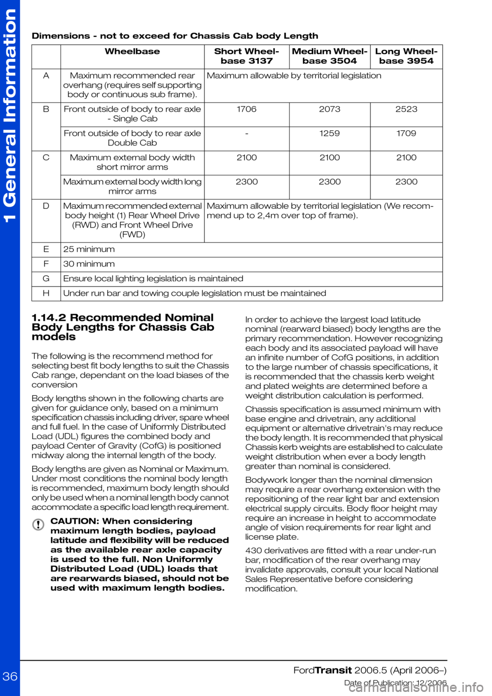
Dimensions - not to exceed for Chassis Cab body Length
Long Wheel-
base 3954
Medium Wheel-
base 3504
Short Wheel-
base 3137
Wheelbase
Maximum allowable by territorial legislationMaximum recommended rear
overhang (requires self supporting
body or continuous sub frame).
A
252320731706Front outside of body to rear axle
- Single Cab
B
17091259-Front outside of body to rear axle
Double Cab
210021002100Maximum external body width
short mirror arms
C
230023002300Maximum external body width long
mirror arms
Maximum allowable by territorial legislation (We recom-
mend up to 2,4m over top of frame).
Maximum recommended external
body height (1) Rear Wheel Drive
(RWD) and Front Wheel Drive
(FWD)
D
25 minimumE
30 minimumF
Ensure local lighting legislation is maintainedG
Under run bar and towing couple legislation must be maintainedH
1.14.2 Recommended Nominal
Body Lengths for Chassis Cab
models
The following is the recommend method for
selecting best fit body lengths to suit the Chassis
Cab range, dependant on the load biases of the
conversion
Body lengths shown in the following charts are
given for guidance only, based on a minimum
specification chassis including driver, spare wheel
and full fuel. In the case of Uniformly Distributed
Load (UDL) figures the combined body and
payload Center of Gravity (CofG) is positioned
midway along the internal length of the body.
Body lengths are given as Nominal or Maximum.
Under most conditions the nominal body length
is recommended, maximum body length should
only be used when a nominal length body cannot
accommodate a specific load length requirement.
CAUTION: When considering
maximum length bodies, payload
latitude and flexibility will be reduced
as the available rear axle capacity
is used to the full. Non Uniformly
Distributed Load (UDL) loads that
are rearwards biased, should not be
used with maximum length bodies.
In order to achieve the largest load latitude
nominal (rearward biased) body lengths are the
primary recommendation. However recognizing
each body and its associated payload will have
an infinite number of CofG positions, in addition
to the large number of chassis specifications, it
is recommended that the chassis kerb weight
and plated weights are determined before a
weight distribution calculation is performed.
Chassis specification is assumed minimum with
base engine and drivetrain, any additional
equipment or alternative drivetrain's may reduce
the body length. It is recommended that physical
Chassis kerb weights are established to calculate
weight distribution when ever a body length
greater than nominal is considered.
Bodywork longer than the nominal dimension
may require a rear overhang extension with the
repositioning of the rear light bar and extension
electrical supply circuits. Body floor height may
require an increase in height to accommodate
angle of vision requirements for rear light and
license plate.
430 derivatives are fitted with a rear under-run
bar, modification of the rear overhang may
invalidate approvals, consult your local National
Sales Representative before considering
modification.
FordTransit 2006.5 (April 2006–)
Date of Publication: 12/2006
1 General Information
36
Page 39 of 234

1.14.4 Recommended Main Load Area Dimensions for Bulkhead with
Depression Driver Side
Height 'C'
(mm) High
Floor
Height 'C'
(mm) Low
Floor
Width 'B'
(mm)
Length 'A'
(mm)
RoofWheelbase
1230133013802230LowShort Wheelbase
1550165012502280MediumShort Wheelbase
1550165012402650MediumMedium Wheelbase
1750185012302610HighMedium Wheelbase
1550165012403100MediumLong Wheelbase
1750185012303060HighLong Wheelbase
1750185012303780HighExtended Frame
FordTransit 2006.5 (April 2006–)
Date of Publication: 12/2006
1 General Information
39E74204CBA
Page 40 of 234

1.14.5 Recommended Main Load Area Dimensions for Bulkhead with
Full Depression
Height 'C'
(mm) High
Floor
Height 'C'
(mm) Low
Floor
Width 'B'
(mm)
Length 'A'
(mm)
RoofWheelbase
1230133013802280LowShort Wheelbase
1550165012502230MediumShort Wheelbase
1550165012402600MediumMedium Wheelbase
1750185012302560HighMedium Wheelbase
1550165012403050MediumLong Wheelbase
1750185012303010HighLong Wheelbase
1750185012303730HighExtended Frame
FordTransit 2006.5 (April 2006–)
Date of Publication: 12/2006
1 General Information
40E74206CBA
Page 42 of 234

Height 'C'
(mm) High
Floor
Height 'C'
(mm) Low
Floor
Width 'B'
(mm)
Length 'A'
(mm)
RoofWheelbase
-133013801480LowShort Wheelbase
-165012501430MediumShort Wheelbase
1550165012401670MediumMedium Wheelbase
1750185012301630HighMedium Wheelbase
1550165012402120MediumLong Wheelbase
1750185012302080HighLong Wheelbase
1750185012302800HighExtended Frame
Right Hand Drive (UK Market Only) includes alternative load box for 8' x 4' sheets
-30013102470Medium and
High
Long Wheelbase
FordTransit 2006.5 (April 2006–)
Date of Publication: 12/2006
1 General Information
42
Page 48 of 234

Van Center of Gravity Critical Zone to EEC Category N1. Non-ABS
Minimum Kerb + Driver
Running Order (Dimensions
mm)
Laden Gross Vehicle Mass (GVM)
with all passengers (Dimensions
mm)
Roof
Height
Model
'G' High
Center
of
Gravity
Max
'F'
Standard
Vehicle
Max
'E'
Design
'D' High
Center
of
Gravity
Max
'C'
Standard
Vehicle
Max
'B' Max'A' Min
Short Wheel Base (SWB)
8257701100128090021268799Low260S
Diesel
8257701119128090021268799Medium260S
Diesel
8257701100128090019361232Low280S
Diesel
8257701119128090019361232Medium280S
Diesel
8257701225128086218091369Low300S
Diesel
8257701224128086218091369Medium300S
Diesel
8257701242128091619111422Low330S
Diesel
8257701240128091619111422Medium330S
Diesel
Medium Wheelbase (MWB)
8257701245128090019671460Low280M
Diesel
8387851265136595419671460Medium280M
Diesel
8257701245128090021781320Low300M
Diesel
8387851265136595421781320Medium300M
Diesel
8387851281136595421781320High300M
Diesel
8257701245128090019361540Low330M
Diesel
8387851406136595419361540Medium330M
Diesel
8387851420136595419361540High330M
Diesel
8387851232136595421281551Low350M
Diesel
8387851400136595421281551Medium350M
Diesel
8387851412136595421281551High350M
Diesel
Long Wheel Base (LWB)
8508001550136595723131750Medium300L
Diesel
FordTransit 2006.5 (April 2006–)
Date of Publication: 12/2006
1 General Information
48
Page 49 of 234
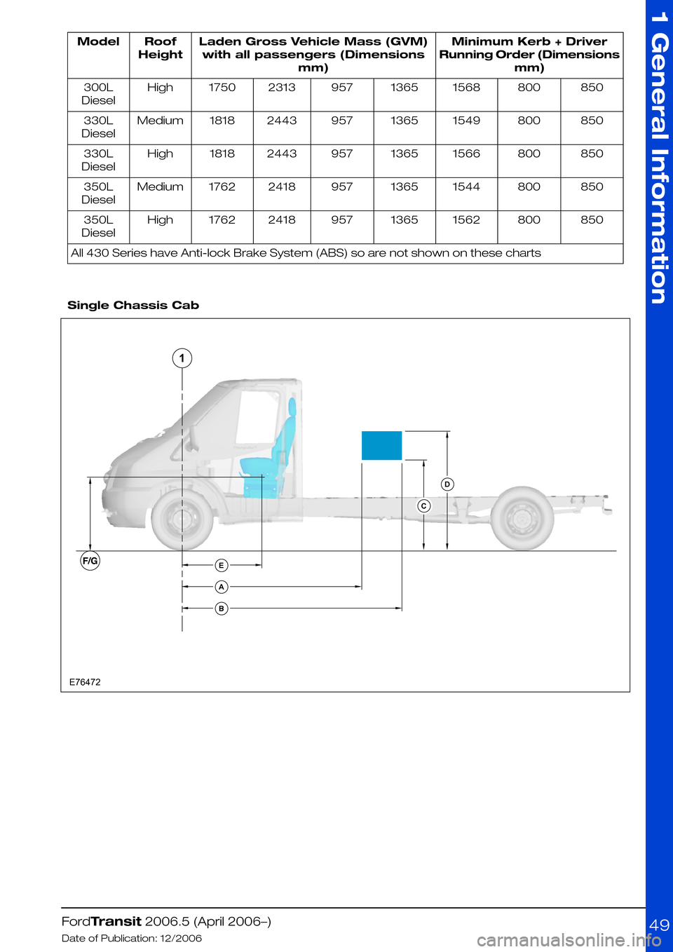
Minimum Kerb + Driver
Running Order (Dimensions
mm)
Laden Gross Vehicle Mass (GVM)
with all passengers (Dimensions
mm)
Roof
Height
Model
8508001568136595723131750High300L
Diesel
8508001549136595724431818Medium330L
Diesel
8508001566136595724431818High330L
Diesel
8508001544136595724181762Medium350L
Diesel
8508001562136595724181762High350L
Diesel
All 430 Series have Anti-lock Brake System (ABS) so are not shown on these charts
Single Chassis Cab
FordTransit 2006.5 (April 2006–)
Date of Publication: 12/2006
1 General Information
49EABCD1E76472
Page 53 of 234
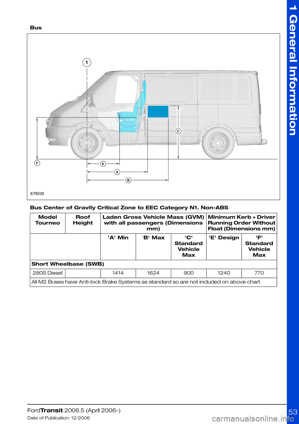
Bus
Bus Center of Gravity Critical Zone to EEC Category N1. Non-ABS
Minimum Kerb + Driver
Running Order Without
Float (Dimensions mm)
Laden Gross Vehicle Mass (GVM)
with all passengers (Dimensions
mm)
Roof
Height
Model
Tourneo
'F'
Standard
Vehicle
Max
'E' Design'C'
Standard
Vehicle
Max
'B' Max'A' Min
Short Wheelbase (SWB)
770124090016241414280S Diesel
All M2 Buses have Anti-lock Brake Systems as standard so are not included on above chart
FordTransit 2006.5 (April 2006–)
Date of Publication: 12/2006
1 General Information
53EABFCE765301
Page 59 of 234
2.3 Rear Suspension
2.3.1 Springs and Spring
Mounting
WARNING: Do not modify, drill, cut
or weld any suspension
components, specifically the
steering gear system, sub-frame or
anti-roll bars, springs or shock
absorbers including mounting
brackets.
CAUTIONS:
When carrying out welding work the
springs must be covered to protect
them against weld splatter.
Do not touch springs with welding
electrodes or welding tongs.
Make sure that components
loosened or removed and reinstalled
are properly reassembled and the
torque set in accordance with
manufactures requirements.
NOTE: Do not modify the wheelbase or add any
type of frame extension to vehicles fitted with
Interactive Vehicle Dynamics (IVD)
NOTE: Do not damage the surface or corrosion
protection of the spring during disassembly and
installation.
NOTE: For detailed information please contact
the Vehicle Converter Advisory Service at
[email protected].
2.3.2 Rear Anti-Roll Bar
Remove the rear anti-roll bar on Chassis Cabs,
except on:
•330 and 350 Front Wheel Drive Chassis Cabs
with Box Body or with another conversion that
gives a similar or higher Centre of Gravity
(CoG) height.
•Dual Rear Wheel Chassis Cabs with Box Body
or with another conversion that gives a similar
or higher Centre of Gravity (CoG) height
FordTransit 2006.5 (April 2006–)
Date of Publication: 12/2006
2 Chassis
59
Page 196 of 234
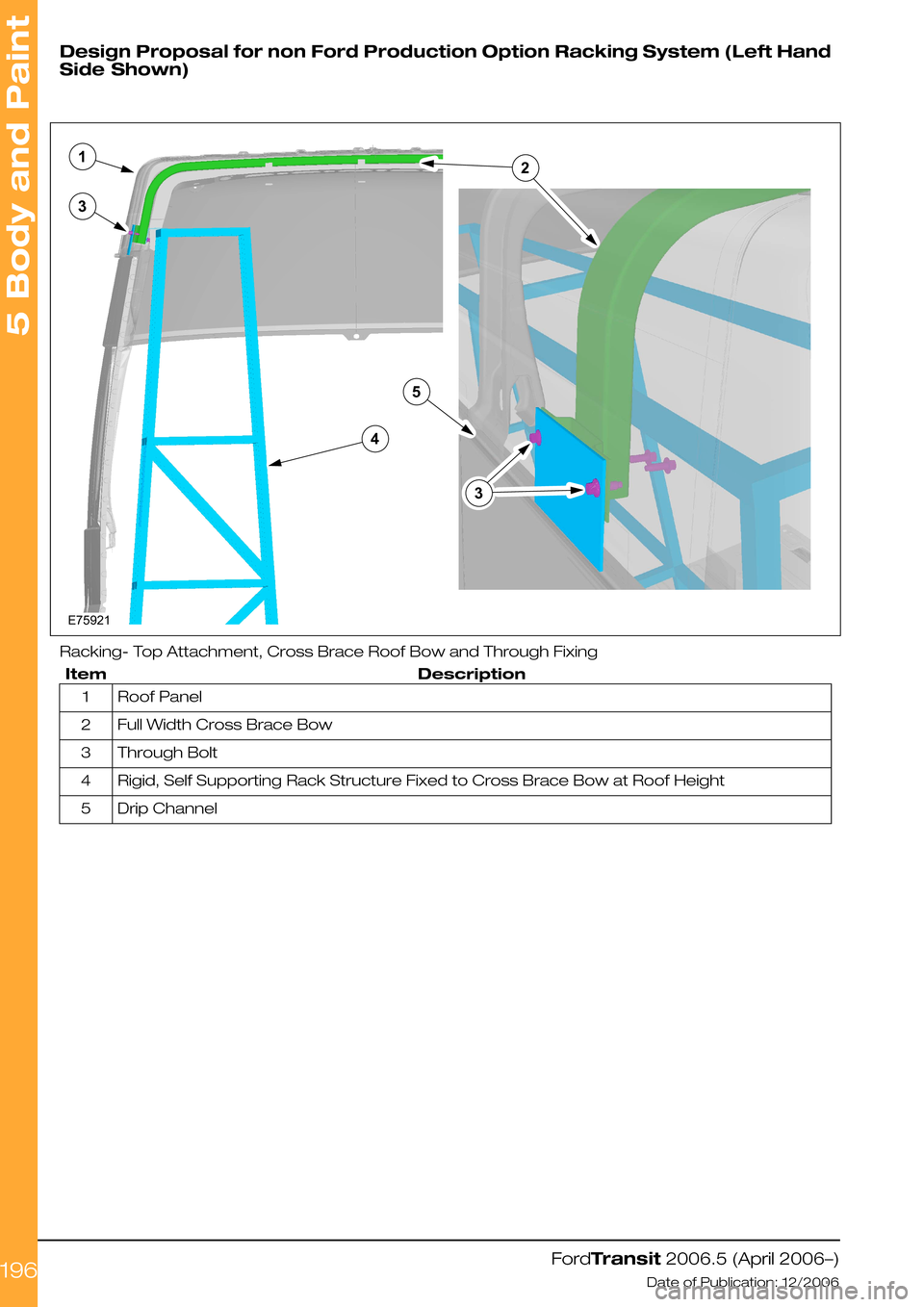
Design Proposal for non Ford Production Option Racking System (Left Hand
Side Shown)
Racking- Top Attachment, Cross Brace Roof Bow and Through Fixing
DescriptionItem
Roof Panel1
Full Width Cross Brace Bow2
Through Bolt3
Rigid, Self Supporting Rack Structure Fixed to Cross Brace Bow at Roof Height4
Drip Channel5
FordTransit 2006.5 (April 2006–)
Date of Publication: 12/2006
5 Body and Paint
196E75921213435
Page 209 of 234

5.5 Seats
5.5.1 Rear Seat Fixings Positions
- Kombi
CAUTION: Do not install seats in the
rear cargo area of a Van.
the following figure shows the second and third
row seat fixing in the floor. These holes and
positions are independent of the wheelbase.
Refer to: 5.6 Glass, Frames and Mechanisms
(page 211).
Rear Floor Seat Fixing Positions
DescriptionItem
Front Axle Center Line1
Floor Height Step on Front wheel Drive Vehicles2
Second Row Seat3
Third Row Seat4
Rear Floor Seat Fixing Position Dimensions (mm)
GFEDCBA
7521048434131284913721787
Cab Van Floor
NOTE: Cab Van Floor Models are currently only
available for use in Motor Caravan applications
Rear seats, if assembled at a Vehicle Converter
/ Modifier, need to be tested according to ECE
R14, 77/541/EEC and ECE R17 by them. It is
recommended to fix the seat frame at three
locations as shown in the following Figure
E74532 which shows the typical design principle
for Cab Van Floor seat frame fixings on top and
underneath the floor. Fixings should be carried
out as U-type bracket clinching the cross beam.
FordTransit 2006.5 (April 2006–)
Date of Publication: 12/2006
5 Body and Paint
2091E74531234ABCDFGE