fuses FORD TRANSIT 2006 7.G Body And Equipment Mounting Section Manual
[x] Cancel search | Manufacturer: FORD, Model Year: 2006, Model line: TRANSIT, Model: FORD TRANSIT 2006 7.GPages: 234, PDF Size: 33.19 MB
Page 4 of 234
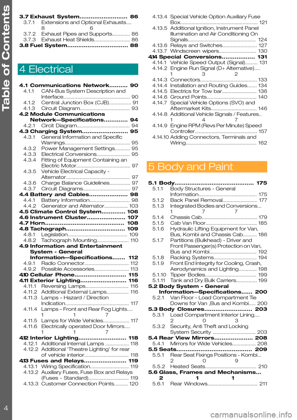
3.7Exhaust System..........................86
3.7.1Extensions and Optional Exhausts....
86
3.7.2Exhaust Pipes and Supports.............86
3.7.3Exhaust Heat Shields..........................86
3.8Fuel System.................................88
4 Electrical
4.1Communications Network..........90
4.1.1CAN-Bus System Description and
Interface................................................90
4.1.2Central Junction Box (CJB)................91
4.1.3Circuit Diagram....................................93
4.2Module Communications
Network—Specifications.............94
4.2.1Circit Diagram......................................94
4.3Charging System.........................95
4.3.1General Information and Specific
Warnings...............................................95
4.3.2Power Management Settings...........95
4.3.3Electrical Conversions........................95
4.3.4Fitting of Equipment Containing an
Electric Motor.......................................97
4.3.5Vehicle Electrical Capacity -
Alternator..............................................97
4.3.6Charge Balance Guidelines...............97
4.3.7Circuit Diagrams..................................97
4.4Battery and Cables.....................98
4.4.1Battery Information.............................98
4.4.2Generator and Alternator.................103
4.5Climate Control System.............106
4.6Instrument Cluster.....................107
4.7Horn...........................................108
4.8Tachograph................................109
4.8.1Legislation...........................................109
4.8.2Tachograph Mounting.......................110
4.9Information and Entertainment
System - General
Information—Specifications.......112
4.9.1Radio Connector................................112
4.9.2Possible Accessories.........................113
4.10Cellular Phone............................115
4.11Exterior Lighting.........................116
4.11.1Reversing Lamps...............................116
4.11.2Additional External Lamps................116
4.11.3Lamps – Hazard / Direction
Indication..............................................117
4.11.4Lamps – Front and Rear Fog Lights....
117
4.11.5Lamps for Wide Vehicles...................117
4.11.6Electrically operated Door Mirrors....
117
4.12Interior Lighting..........................118
4.12.1Additional Internal Lamps .................118
4.12.2Additional 'Theatre Lighting' for rear
of vehicle interior................................118
4.13Fuses and Relays.......................119
4.13.1Wiring Specification............................119
4.13.2Auxiliary Fuses, Fuse Box and Relays
(Fuses - Standard).............................119
4.13.3Customer Connection Points..........120
4.13.4Special Vehicle Option Auxiliary Fuse
Box........................................................121
4.13.5Additional Ignition, Instrument Panel
Illumination and Air Conditioning On
Signals.................................................124
4.13.6Relays and Switches.........................127
4.13.7Windscreen wipers...........................130
4.14Special Conversions..................131
4.14.1Vehicle Speed Output (Signal).........131
4.14.2Engine Run Signal (D+ Alternative)....
132
4.14.3Connectors.........................................133
4.14.4Installation and Routing Guides.......134
4.14.5Electrics for Tow bar.........................136
4.14.6Ground Points....................................140
4.14.7Special Vehicle Options (SVO) and
Aftermarket Kits.................................146
4.14.8Additional Vehicle Signals / Features..
147
4.14.9Engine RPM (Revs Per Minute) Speed
Controller.............................................157
4.14.10Adding Connectors, Terminals and
Wiring...................................................162
5 Body and Paint
5.1Body...........................................175
5.1.1Body Structures - General
Information..........................................175
5.1.2Back Panel Removal.........................177
5.1.3Integrated Bodies and Conversions...
177
5.1.4Chassis Cab........................................179
5.1.5Cab Van Floor.....................................185
5.1.6Hydraulic Lifting Equipment for Van,
Bus, Kombi and Chassis Cab..........186
5.1.7Partitions (Bulkhead) - Driver and
Front Passenger(s) Protection on Van,
Bus and Kombi..................................192
5.1.8Racking Systems...............................194
5.1.9Front End Integrity for Cooling, Crash,
Aerodynamics and Lighting.............198
5.1.10Tipper Bodies.....................................199
5.1.11Tank and Dry Bulk Carriers...............199
5.2Body System - General
Information—Specifications......200
5.2.1Van Floor - Load Compartment Tie
Downs for Van ,Bus and Kombi.....200
5.3Body Closures..........................203
5.3.1Load Compartment Interior Lining....
203
5.3.2Security, Anti Theft and Locking
System Security ...............................203
5.4Rear View Mirrors.....................208
5.4.1Mirrors for Wide Vehicles.................208
5.5Seats.........................................209
5.5.1Rear Seat Fixings Positions - Kombi...
209
5.5.2Heated Seats.....................................210
5.6Glass, Frames and Mechanisms...
211
5.6.1Rear Windows....................................211
Table of Contents
4
Page 14 of 234

1.4 Conversion Type
NOTE: The following tables are for
guidance only. Full reference to the Body
and Equipment Mounting Manual should
be made prior to starting any
conversion.
NOTE: For any conversions requiring
electrical power
Refer to: 4.1 Communications Network (page 90).
Refer to: 4.13 Fuses and Relays (page 119).
The BEMM contains general and specific
recommendations covering conversions to the
new Transit range of vehicles. To assist users
locate information by conversion type the
following tables contain the relevant links within
this Manual.
FordTransit 2006.5 (April 2006–)
Date of Publication: 12/2006
1 General Information
14
Page 20 of 234

Refrigerated Vehicles
Refer to: 1.8 End of Life Vehicle (ELV) Directive (page 26).
Van Conver-
sion
Refer to: 1.14 (page 34).
Refer to: 4.4 Battery and Cables (page 98).
(Also Generator and Alternator).
Refer to: 4.5 Climate Control System (page 106).
Refer to: 4.13 Fuses and Relays (page 119).
Refer to: 5.1 Body (page 175).
(Integrated Bodies and Conversions).
Refer to: 5.7 Roof Opening Panel (page 214).
(Roof Racks).
Refer to: 1.8 End of Life Vehicle (ELV) Directive (page 26).
Box Body
Conversion
Refer to: 1.14 (page 34).
Refer to: 4.4 Battery and Cables (page 98).
(Also generator and Alternator).
Refer to: 4.5 Climate Control System (page 106).
Refer to: 4.13 Fuses and Relays (page 119).
Refer to: 5.1 Body (page 175).
(Integrated Bodies and Conversions).
Refer to: 5.7 Roof Opening Panel (page 214).
(Roof Racks).
Refer to: 3.3 Accessory Drive (page 77).Compressor
Installation
FordTransit 2006.5 (April 2006–)
Date of Publication: 12/2006
1 General Information
20
Page 21 of 234
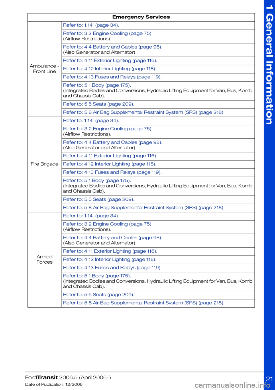
Emergency Services
Refer to: 1.14 (page 34).
Ambulance -
Front Line
Refer to: 3.2 Engine Cooling (page 75).
(Airflow Restrictions).
Refer to: 4.4 Battery and Cables (page 98).
(Also Generator and Alternator).
Refer to: 4.11 Exterior Lighting (page 116).
Refer to: 4.12 Interior Lighting (page 118).
Refer to: 4.13 Fuses and Relays (page 119).
Refer to: 5.1 Body (page 175).
(Integrated Bodies and Conversions, Hydraulic Lifting Equipment for Van, Bus, Kombi
and Chassis Cab).
Refer to: 5.5 Seats (page 209).
Refer to: 5.8 Air Bag Supplemental Restraint System (SRS) (page 218).
Refer to: 1.14 (page 34).
Fire Brigade
Refer to: 3.2 Engine Cooling (page 75).
(Airflow Restrictions).
Refer to: 4.4 Battery and Cables (page 98).
(Also Generator and Alternator).
Refer to: 4.11 Exterior Lighting (page 116).
Refer to: 4.12 Interior Lighting (page 118).
Refer to: 4.13 Fuses and Relays (page 119).
Refer to: 5.1 Body (page 175).
(Integrated Bodies and Conversions, Hydraulic Lifting Equipment for Van, Bus, Kombi
and Chassis Cab).
Refer to: 5.5 Seats (page 209).
Refer to: 5.8 Air Bag Supplemental Restraint System (SRS) (page 218).
Refer to: 1.14 (page 34).
Armed
Forces
Refer to: 3.2 Engine Cooling (page 75).
(Airflow Restrictions).
Refer to: 4.4 Battery and Cables (page 98).
(Also Generator and Alternator).
Refer to: 4.11 Exterior Lighting (page 116).
Refer to: 4.12 Interior Lighting (page 118).
Refer to: 4.13 Fuses and Relays (page 119).
Refer to: 5.1 Body (page 175).
(Integrated Bodies and Conversions, Hydraulic Lifting Equipment for Van, Bus, Kombi
and Chassis Cab).
Refer to: 5.5 Seats (page 209).
Refer to: 5.8 Air Bag Supplemental Restraint System (SRS) (page 218).
FordTransit 2006.5 (April 2006–)
Date of Publication: 12/2006
1 General Information
21
Page 22 of 234
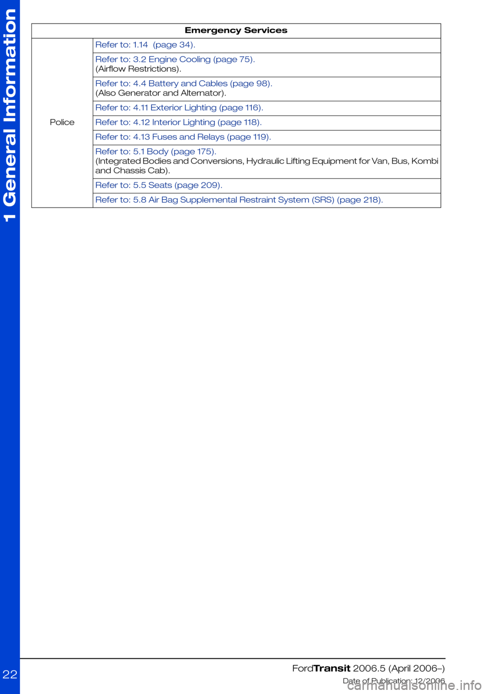
Emergency Services
Refer to: 1.14 (page 34).
Police
Refer to: 3.2 Engine Cooling (page 75).
(Airflow Restrictions).
Refer to: 4.4 Battery and Cables (page 98).
(Also Generator and Alternator).
Refer to: 4.11 Exterior Lighting (page 116).
Refer to: 4.12 Interior Lighting (page 118).
Refer to: 4.13 Fuses and Relays (page 119).
Refer to: 5.1 Body (page 175).
(Integrated Bodies and Conversions, Hydraulic Lifting Equipment for Van, Bus, Kombi
and Chassis Cab).
Refer to: 5.5 Seats (page 209).
Refer to: 5.8 Air Bag Supplemental Restraint System (SRS) (page 218).
FordTransit 2006.5 (April 2006–)
Date of Publication: 12/2006
1 General Information
22
Page 96 of 234
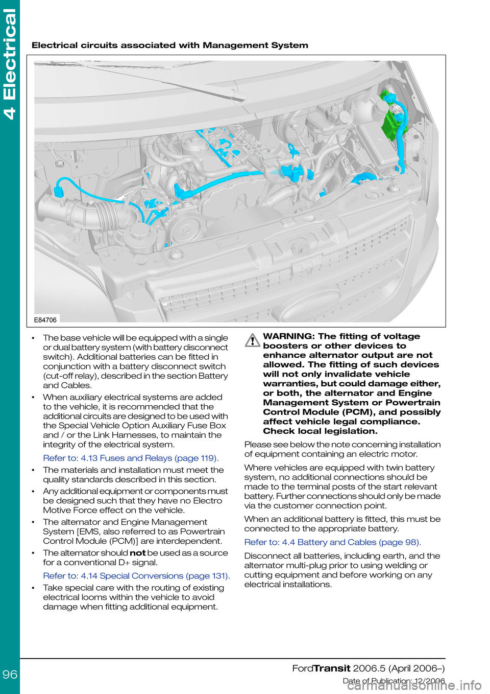
Electrical circuits associated with Management System
•The base vehicle will be equipped with a single
or dual battery system (with battery disconnect
switch). Additional batteries can be fitted in
conjunction with a battery disconnect switch
(cut-off relay), described in the section Battery
and Cables.
•When auxiliary electrical systems are added
to the vehicle, it is recommended that the
additional circuits are designed to be used with
the Special Vehicle Option Auxiliary Fuse Box
and / or the Link Harnesses, to maintain the
integrity of the electrical system.
Refer to: 4.13 Fuses and Relays (page 119).
•The materials and installation must meet the
quality standards described in this section.
•Any additional equipment or components must
be designed such that they have no Electro
Motive Force effect on the vehicle.
•The alternator and Engine Management
System [EMS, also referred to as Powertrain
Control Module (PCM)] are interdependent.
•The alternator should not be used as a source
for a conventional D+ signal.
Refer to: 4.14 Special Conversions (page 131).
•Take special care with the routing of existing
electrical looms within the vehicle to avoid
damage when fitting additional equipment.
WARNING: The fitting of voltage
boosters or other devices to
enhance alternator output are not
allowed. The fitting of such devices
will not only invalidate vehicle
warranties, but could damage either,
or both, the alternator and Engine
Management System or Powertrain
Control Module (PCM), and possibly
affect vehicle legal compliance.
Check local legislation.
Please see below the note concerning installation
of equipment containing an electric motor.
Where vehicles are equipped with twin battery
system, no additional connections should be
made to the terminal posts of the start relevant
battery. Further connections should only be made
via the customer connection point.
When an additional battery is fitted, this must be
connected to the appropriate battery.
Refer to: 4.4 Battery and Cables (page 98).
Disconnect all batteries, including earth, and the
alternator multi-plug prior to using welding or
cutting equipment and before working on any
electrical installations.
FordTransit 2006.5 (April 2006–)
Date of Publication: 12/2006
4 Electrical
96E84706
Page 97 of 234
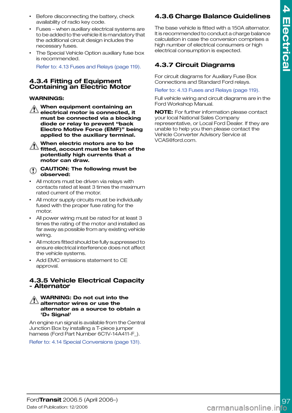
•Before disconnecting the battery, check
availability of radio key code.
•Fuses – when auxiliary electrical systems are
to be added to the vehicle it is mandatory that
the additional circuit design includes the
necessary fuses.
•The Special Vehicle Option auxiliary fuse box
is recommended.
Refer to: 4.13 Fuses and Relays (page 119).
4.3.4 Fitting of Equipment
Containing an Electric Motor
WARNINGS:
When equipment containing an
electrical motor is connected, it
must be connected via a blocking
diode or relay to prevent “back
Electro Motive Force (EMF)” being
applied to the auxiliary terminal.
When electric motors are to be
fitted, account must be taken of the
potentially high currents that a
motor can draw.
CAUTION: The following must be
observed:
•All motors must be driven via relays with
contacts rated at least 3 times the maximum
rated current of the motor.
•All motor supply circuits must be individually
fused with the proper fuse rating for the
motor.
•All power wiring must be rated for at least 3
times the rating of the motor and installed as
far away as possible from any existing vehicle
wiring.
•All motors fitted should be fully suppressed to
ensure electrical interference does not affect
the vehicle systems.
•Add EMC emissions statement to CE
approval.
4.3.5 Vehicle Electrical Capacity
- Alternator
WARNING: Do not cut into the
alternator wires or use the
alternator as a source to obtain a
'D+ Signal'
An engine run signal is available from the Central
Junction Box by installing a T-piece jumper
harness (Ford Part Number 6C1V-14A411-F_).
Refer to: 4.14 Special Conversions (page 131).
4.3.6 Charge Balance Guidelines
The base vehicle is fitted with a 150A alternator.
It is recommended to conduct a charge balance
calculation in case the conversion comprises a
high number of electrical consumers or high
electrical consumption is expected.
4.3.7 Circuit Diagrams
For circuit diagrams for Auxiliary Fuse Box
Connections and Standard Ford relays.
Refer to: 4.13 Fuses and Relays (page 119).
Full vehicle wiring and circuit diagrams are in the
Ford Workshop Manual.
NOTE: For further information please contact
your local National Sales Company
representative, or Local Ford Dealer. If they are
unable to help you then please contact the
Vehicle Converter Advisory Service at
[email protected].
FordTransit 2006.5 (April 2006–)
Date of Publication: 12/2006
4 Electrical
97
Page 116 of 234
4.11 Exterior Lighting
Where the following text makes reference to the
addition of wires
Refer to: 4.14 Special Conversions (page 131).
(Adding Connectors, Terminals and Wiring)
WARNING: Make sure that the
modified vehicle complies with all
relevant legal requirements.
4.11.1 Reversing Lamps
These are hard-wired, activated by the reversing
switch on the transmission and passing through
the Central Junction Box where the signal is
sensed. A marginal increase in current (via a relay
or buffered electrical input) is permissible to
trigger a rear-view camera system, or audible
device.
4.11.2 Additional External Lamps
All power for additional exterior lamps must be
taken through the Auxiliary Fuse Box with a
suitable switch and / or relay as required.
Refer to: 4.13 Fuses and Relays (page 119).
• If CAT 6 directional indicators are to be fitted,
the Central Junction Box will need to be
configured for this.
• The load on the reversing lamps should not
exceed a total of 3A (42W).
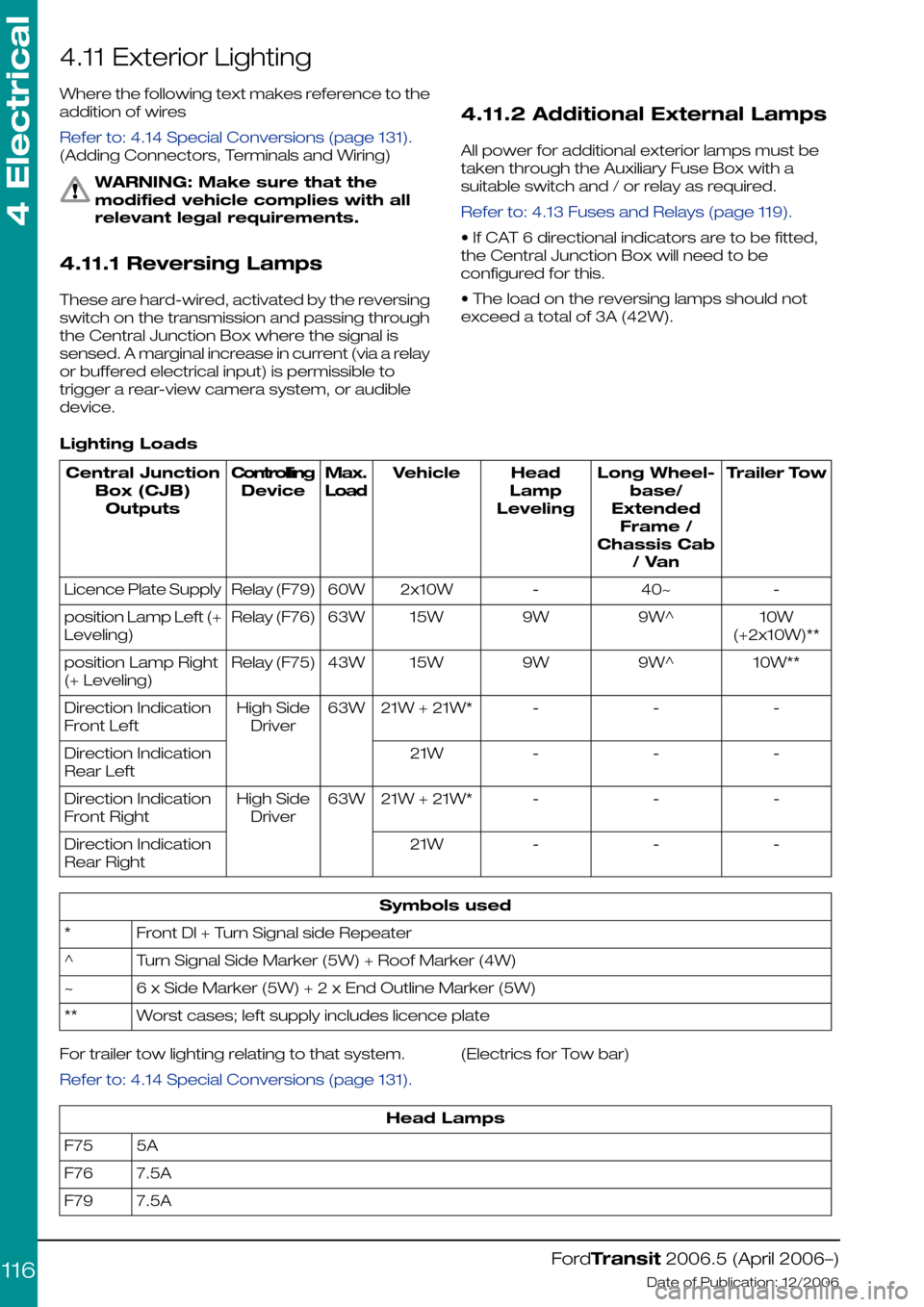
Lighting Loads
Trailer TowLong Wheel-
base/
Extended
Frame /
Chassis Cab
/ Van
Head
Lamp
Leveling
VehicleMax.
Load
Controlling
Device
Central Junction
Box (CJB)
Outputs
-40~-2x10W60WRelay (F79)Licence Plate Supply
10W
(+2x10W)**
9W^9W15W63WRelay (F76)position Lamp Left (+
Leveling)
10W**9W^9W15W43WRelay (F75)position Lamp Right
(+ Leveling)
---21W + 21W*63WHigh Side
Driver
Direction Indication
Front Left
---21WDirection Indication
Rear Left
---21W + 21W*63WHigh Side
Driver
Direction Indication
Front Right
---21WDirection Indication
Rear Right
Symbols used
Front Dl + Turn Signal side Repeater*
Turn Signal Side Marker (5W) + Roof Marker (4W)^
6 x Side Marker (5W) + 2 x End Outline Marker (5W)~
Worst cases; left supply includes licence plate**
For trailer tow lighting relating to that system.
Refer to: 4.14 Special Conversions (page 131).
(Electrics for Tow bar)
Head Lamps
5AF75
7.5AF76
7.5AF79
FordTransit 2006.5 (April 2006–)
Date of Publication: 12/2006
4 Electrical
116
Page 118 of 234
4.12 Interior Lighting
4.12.1 Additional Internal Lamps
Additional cabin interior lighting may be obtained
by directly accessing the connector inside the
dome lamp in the cab.
Additional load space interior lighting may be
obtained by directly accessing the connector
inside the load space lamps in the load space
area.
CAUTION: The maximum total
internal lamp load must not exceed
5A (75W)
Power for the Interior Lights - cabin and
cargo areas – comes from the battery save
system (Central Junction Box pin C2-31), and for
vehicles with power locking,* the circuit for each
area is controlled by a separate pin on the Central
Junction Box:
•Front (cabin) lights, pin C2-22
•Rear (cargo) lights, pin C2-27 wire not present
on chassis cab and cab-van-floor vehicles
* with manual locking vehicles, control of interior
lighting is done directly through the door contact
switches. All vehicles, however, utilise the battery
saver relay to provide power for internal lighting
for a limited time.
Each of these pins on the Central Junction Box
can take a load of 75W. Lights that are controlled
by the battery save circuit will extinguish 30 to
180 minutes after ignition off (dependent on
vehicle configuration).
4.12.2 Additional 'Theatre
Lighting' for rear of vehicle
interior
For chassis cab or cab-van floor (and camper)
vehicles, rear lighting is not utilised and so there
is no wire to pin C2-27. However, converters can
add their own lights (up to the max. load) via the
battery save or a separate switchable feed, by
adding a pre-crimped wire and terminal to
connector C2. This is located on the Central
Junction Box behind the glove box on the
passenger side (please refer to Figures E84705
and E84712).
Refer to: 4.14 Special Conversions (page 131).
(Adding connectors, Terminals and Wiring)
Where higher wattage installations are required,
these should be taken through the Auxiliary Fuse
Box with a suitable switch and / or relay as
required.
Refer to: 4.13 Fuses and Relays (page 119).
FordTransit 2006.5 (April 2006–)
Date of Publication: 12/2006
4 Electrical
118
Page 119 of 234
4.13 Fuses and Relays
4.13.1 Wiring Specification
When designing wire installations for additional
equipment use the cable size recommended by
the equipment manufacturer or select a suitable
size from the Current Rating Wire Sizes
specifications chart.
Refer to: 4.2 (page 94).
Wiring consists a soft annealed copper core in
accordance with DIN 57201 (VDDE 0201)
sheathed in Hypalon or irradiated PVC.
For 0,5mm cable an alternative material with
conductor E-CU F20 or F21 in accordance with
DIN 40500 sheathed in cross linked PVC is
available.
4.13.2 Auxiliary Fuses, Fuse Box
and Relays (Fuses - Standard)
WARNING: No increase in existing
vehicle standard fuse capacity is
allowed under any circumstances.
There are no spare fuses in the
Engine Junction Box, Standard Relay
Box or Central Junction Box. The
vehicle converter/modifier must
provide additional fuses as required.
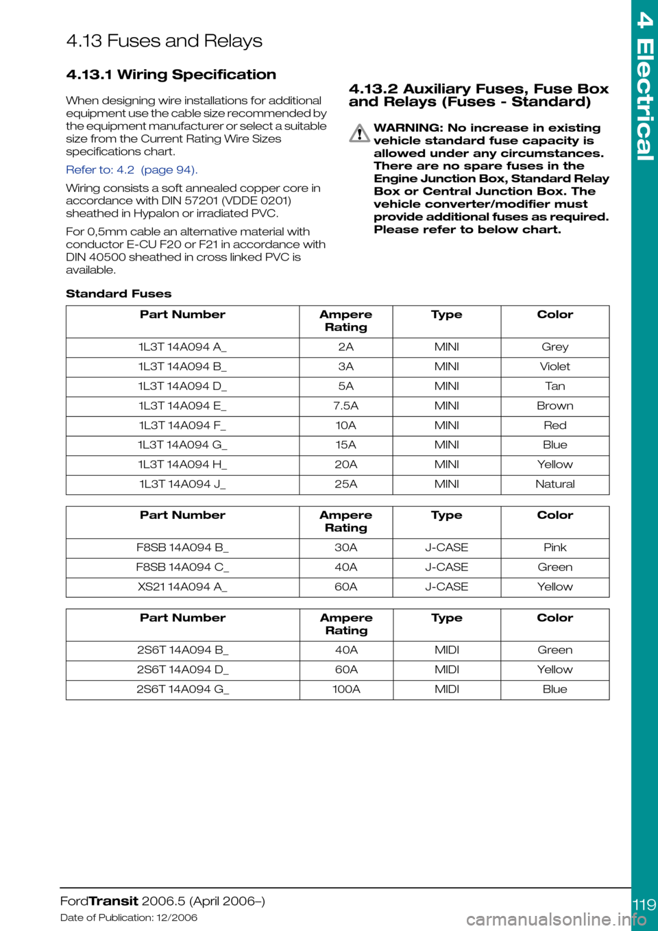
Please refer to below chart.
Standard Fuses
ColorTypeAmpere
Rating
Part Number
GreyMINI2A1L3T 14A094 A_
VioletMINI3A1L3T 14A094 B_
TanMINI5A1L3T 14A094 D_
BrownMINI7.5A1L3T 14A094 E_
RedMINI10A1L3T 14A094 F_
BlueMINI15A1L3T 14A094 G_
YellowMINI20A1L3T 14A094 H_
NaturalMINI25A1L3T 14A094 J_
ColorTypeAmpere
Rating
Part Number
PinkJ-CASE30AF8SB 14A094 B_
GreenJ-CASE40AF8SB 14A094 C_
YellowJ-CASE60AXS21 14A094 A_
ColorTypeAmpere
Rating
Part Number
GreenMIDI40A2S6T 14A094 B_
YellowMIDI60A2S6T 14A094 D_
BlueMIDI100A2S6T 14A094 G_
FordTransit 2006.5 (April 2006–)
Date of Publication: 12/2006
4 Electrical
119