wheel FORD TRANSIT 2006 7.G Body And Equipment Mounting Section Manual
[x] Cancel search | Manufacturer: FORD, Model Year: 2006, Model line: TRANSIT, Model: FORD TRANSIT 2006 7.GPages: 234, PDF Size: 33.19 MB
Page 3 of 234
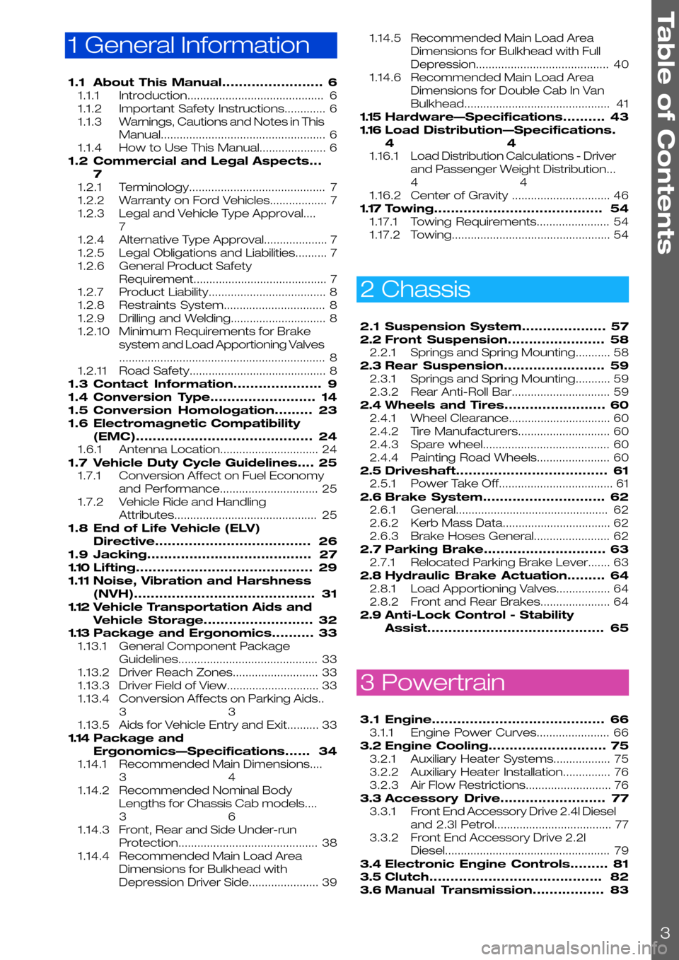
1 General Information
1.1About This Manual........................6
1.1.1Introduction...........................................6
1.1.2Important Safety Instructions.............6
1.1.3Warnings, Cautions and Notes in This
Manual....................................................6
1.1.4How to Use This Manual.....................6
1.2Commercial and Legal Aspects...
7
1.2.1Terminology...........................................7
1.2.2Warranty on Ford Vehicles..................7
1.2.3Legal and Vehicle Type Approval....
7
1.2.4Alternative Type Approval....................7
1.2.5Legal Obligations and Liabilities..........7
1.2.6General Product Safety
Requirement..........................................7
1.2.7Product Liability.....................................8
1.2.8Restraints System................................8
1.2.9Drilling and Welding..............................8
1.2.10Minimum Requirements for Brake
system and Load Apportioning Valves
.................................................................8
1.2.11Road Safety...........................................8
1.3Contact Information.....................9
1.4Conversion Type.........................14
1.5Conversion Homologation.........23
1.6Electromagnetic Compatibility
(EMC)..........................................24
1.6.1Antenna Location...............................24
1.7Vehicle Duty Cycle Guidelines....25
1.7.1Conversion Affect on Fuel Economy
and Performance...............................25
1.7.2Vehicle Ride and Handling
Attributes.............................................25
1.8End of Life Vehicle (ELV)
Directive.....................................26
1.9Jacking.......................................27
1.10Lifting..........................................29
1.11Noise, Vibration and Harshness
(NVH)...........................................31
1.12Vehicle Transportation Aids and
Vehicle Storage..........................32
1.13Package and Ergonomics..........33
1.13.1General Component Package
Guidelines............................................33
1.13.2Driver Reach Zones...........................33
1.13.3Driver Field of View.............................33
1.13.4Conversion Affects on Parking Aids..
33
1.13.5Aids for Vehicle Entry and Exit..........33
1.14Package and
Ergonomics—Specifications......34
1.14.1Recommended Main Dimensions....
34
1.14.2Recommended Nominal Body
Lengths for Chassis Cab models....
36
1.14.3Front, Rear and Side Under-run
Protection............................................38
1.14.4Recommended Main Load Area
Dimensions for Bulkhead with
Depression Driver Side......................39
1.14.5Recommended Main Load Area
Dimensions for Bulkhead with Full
Depression..........................................40
1.14.6Recommended Main Load Area
Dimensions for Double Cab In Van
Bulkhead..............................................41
1.15Hardware—Specifications..........43
1.16Load Distribution—Specifications.
44
1.16.1Load Distribution Calculations - Driver
and Passenger Weight Distribution...
44
1.16.2Center of Gravity ...............................46
1.17Towing........................................54
1.17.1Towing Requirements.......................54
1.17.2Towing..................................................54
2 Chassis
2.1Suspension System....................57
2.2Front Suspension.......................58
2.2.1Springs and Spring Mounting...........58
2.3Rear Suspension........................59
2.3.1Springs and Spring Mounting...........59
2.3.2Rear Anti-Roll Bar...............................59
2.4Wheels and Tires........................60
2.4.1Wheel Clearance................................60
2.4.2Tire Manufacturers.............................60
2.4.3Spare wheel........................................60
2.4.4Painting Road Wheels.......................60
2.5Driveshaft....................................61
2.5.1Power Take Off....................................61
2.6Brake System.............................62
2.6.1General................................................62
2.6.2Kerb Mass Data..................................62
2.6.3Brake Hoses General........................62
2.7Parking Brake.............................63
2.7.1Relocated Parking Brake Lever.......63
2.8Hydraulic Brake Actuation.........64
2.8.1Load Apportioning Valves.................64
2.8.2Front and Rear Brakes......................64
2.9Anti-Lock Control - Stability
Assist..........................................65
3 Powertrain
3.1Engine.........................................66
3.1.1Engine Power Curves.......................66
3.2Engine Cooling............................75
3.2.1Auxiliary Heater Systems..................75
3.2.2Auxiliary Heater Installation...............76
3.2.3Air Flow Restrictions...........................76
3.3Accessory Drive.........................77
3.3.1Front End Accessory Drive 2.4l Diesel
and 2.3l Petrol.....................................77
3.3.2Front End Accessory Drive 2.2l
Diesel....................................................79
3.4Electronic Engine Controls.........81
3.5Clutch.........................................82
3.6Manual Transmission.................83
Table of Contents
3
Page 5 of 234
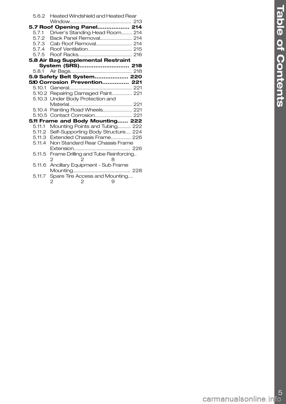
5.6.2Heated Windshield and Heated Rear
Window..............................................213
5.7Roof Opening Panel..................214
5.7.1Driver's Standing Head Room........214
5.7.2Back Panel Removal........................214
5.7.3Cab Roof Removal...........................214
5.7.4Roof Ventilation.................................215
5.7.5Roof Racks........................................216
5.8Air Bag Supplemental Restraint
System (SRS)............................218
5.8.1Air Bags..............................................218
5.9Safety Belt System...................220
5.10Corrosion Prevention...............221
5.10.1General...............................................221
5.10.2Repairing Damaged Paint...............221
5.10.3Under Body Protection and
Material...............................................221
5.10.4Painting Road Wheels......................221
5.10.5Contact Corrosion............................221
5.11Frame and Body Mounting......222
5.11.1Mounting Points and Tubing..........222
5.11.2Self-Supporting Body Structure....224
5.11.3Extended Chassis Frame...............226
5.11.4Non Standard Rear Chassis Frame
Extension..........................................226
5.11.5Frame Drilling and Tube Reinforcing..
228
5.11.6Ancillary Equipment - Sub Frame
Mounting...........................................228
5.11.7Spare Tire Access and Mounting....
229
Table of Contents
5
Page 17 of 234
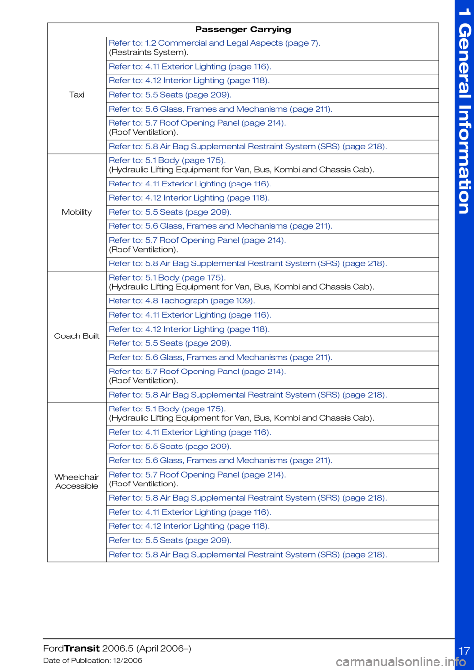
Passenger Carrying
Refer to: 1.2 Commercial and Legal Aspects (page 7).
Taxi
(Restraints System).
Refer to: 4.11 Exterior Lighting (page 116).
Refer to: 4.12 Interior Lighting (page 118).
Refer to: 5.5 Seats (page 209).
Refer to: 5.6 Glass, Frames and Mechanisms (page 211).
Refer to: 5.7 Roof Opening Panel (page 214).
(Roof Ventilation).
Refer to: 5.8 Air Bag Supplemental Restraint System (SRS) (page 218).
Refer to: 5.1 Body (page 175).
Mobility
(Hydraulic Lifting Equipment for Van, Bus, Kombi and Chassis Cab).
Refer to: 4.11 Exterior Lighting (page 116).
Refer to: 4.12 Interior Lighting (page 118).
Refer to: 5.5 Seats (page 209).
Refer to: 5.6 Glass, Frames and Mechanisms (page 211).
Refer to: 5.7 Roof Opening Panel (page 214).
(Roof Ventilation).
Refer to: 5.8 Air Bag Supplemental Restraint System (SRS) (page 218).
Refer to: 5.1 Body (page 175).
Coach Built
(Hydraulic Lifting Equipment for Van, Bus, Kombi and Chassis Cab).
Refer to: 4.8 Tachograph (page 109).
Refer to: 4.11 Exterior Lighting (page 116).
Refer to: 4.12 Interior Lighting (page 118).
Refer to: 5.5 Seats (page 209).
Refer to: 5.6 Glass, Frames and Mechanisms (page 211).
Refer to: 5.7 Roof Opening Panel (page 214).
(Roof Ventilation).
Refer to: 5.8 Air Bag Supplemental Restraint System (SRS) (page 218).
Refer to: 5.1 Body (page 175).
Wheelchair
Accessible
(Hydraulic Lifting Equipment for Van, Bus, Kombi and Chassis Cab).
Refer to: 4.11 Exterior Lighting (page 116).
Refer to: 5.5 Seats (page 209).
Refer to: 5.6 Glass, Frames and Mechanisms (page 211).
Refer to: 5.7 Roof Opening Panel (page 214).
(Roof Ventilation).
Refer to: 5.8 Air Bag Supplemental Restraint System (SRS) (page 218).
Refer to: 4.11 Exterior Lighting (page 116).
Refer to: 4.12 Interior Lighting (page 118).
Refer to: 5.5 Seats (page 209).
Refer to: 5.8 Air Bag Supplemental Restraint System (SRS) (page 218).
FordTransit 2006.5 (April 2006–)
Date of Publication: 12/2006
1 General Information
17
Page 25 of 234
1.7 Vehicle Duty Cycle Guidelines
It is necessary to take into account the customer
usage profile and the anticipated vehicle duty
cycles of the modified vehicle in order to choose
the appropriate specification of the base vehicle.
It is necessary to select the appropriate drive,
engine, gear ratio, gross vehicle mass, gross train
mass, axle plates and payloads of the base
vehicle to match the customer requirements.
Where possible make sure that the base vehicle
is ordered with any necessary plant fit options.
NOTE: For further information please contact
your local National Sales Company
representative, or Local Ford Dealer. If they are
unable to help you then please contact the
Vehicle Converter Advisory Service at
[email protected].
A high numeric gear ratio is recommended for
vehicles with customer requirements for:
•high payload
•trailer tow
•frequent stop-and-go cycles
•high altitude and gradients
•terrain conditions such as found on building
and construction sites
Rear wheel drive is recommended for high
traction in combination with a high trailer weight
Front wheel drive is recommended for low
conversion weight
1.7.1 Conversion Affect on Fuel
Economy and Performance
Any conversion may effect the fuel consumption
and performance depending on the
aerodynamics and the weight added by the
conversion. The published information for fuel
consumption and performance of the base
vehicle therefore may not be valid. It is advisable
to control the weight, but without deteriorating
other vehicle attributes and functions (especially
those related to safety and durability).
1.7.2 Vehicle Ride and Handling
Attributes
CAUTION: Do not exceed the axle
plate, gross vehicle mass, trailer
plate and gross trailer mass limits.
Due to the displacement of the center of gravity
occurred by the conversion the ride and handling
attributes may be different to the base vehicle.
NOTE: This vehicle should be evaluated for safe
operation prior to sale
FordTransit 2006.5 (April 2006–)
Date of Publication: 12/2006
1 General Information
25
Page 27 of 234
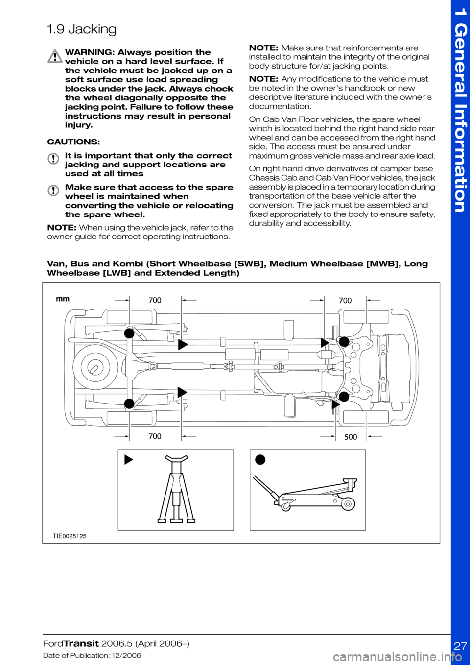
1.9 Jacking
WARNING: Always position the
vehicle on a hard level surface. If
the vehicle must be jacked up on a
soft surface use load spreading
blocks under the jack. Always chock
the wheel diagonally opposite the
jacking point. Failure to follow these
instructions may result in personal
injury.
CAUTIONS:
It is important that only the correct
jacking and support locations are
used at all times
Make sure that access to the spare
wheel is maintained when
converting the vehicle or relocating
the spare wheel.
NOTE: When using the vehicle jack, refer to the
owner guide for correct operating instructions.
NOTE: Make sure that reinforcements are
installed to maintain the integrity of the original
body structure for/at jacking points.
NOTE: Any modifications to the vehicle must
be noted in the owner's handbook or new
descriptive literature included with the owner's
documentation.
On Cab Van Floor vehicles, the spare wheel
winch is located behind the right hand side rear
wheel and can be accessed from the right hand
side. The access must be ensured under
maximum gross vehicle mass and rear axle load.
On right hand drive derivatives of camper base
Chassis Cab and Cab Van Floor vehicles, the jack
assembly is placed in a temporary location during
transportation of the base vehicle after the
conversion. The jack must be assembled and
fixed appropriately to the body to ensure safety,
durability and accessibility.
Van, Bus and Kombi (Short Wheelbase [SWB], Medium Wheelbase [MWB], Long
Wheelbase [LWB] and Extended Length)
FordTransit 2006.5 (April 2006–)
Date of Publication: 12/2006
1 General Information
27TIE0025125
Page 29 of 234
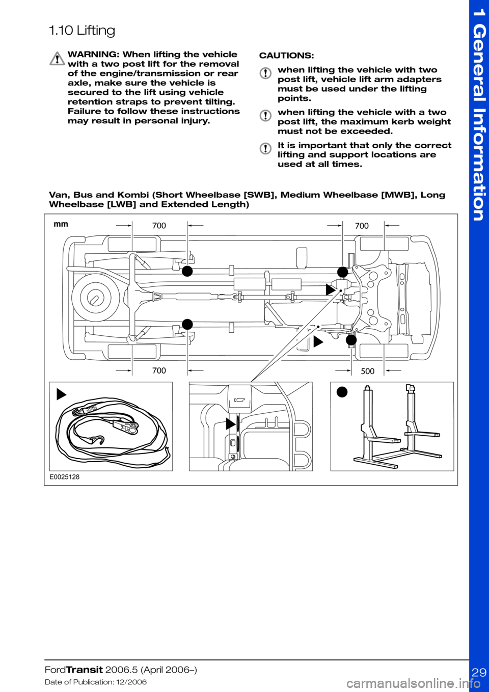
1.10 Lifting
WARNING: When lifting the vehicle
with a two post lift for the removal
of the engine/transmission or rear
axle, make sure the vehicle is
secured to the lift using vehicle
retention straps to prevent tilting.
Failure to follow these instructions
may result in personal injury.
CAUTIONS:
when lifting the vehicle with two
post lift, vehicle lift arm adapters
must be used under the lifting
points.
when lifting the vehicle with a two
post lift, the maximum kerb weight
must not be exceeded.
It is important that only the correct
lifting and support locations are
used at all times.
Van, Bus and Kombi (Short Wheelbase [SWB], Medium Wheelbase [MWB], Long
Wheelbase [LWB] and Extended Length)
FordTransit 2006.5 (April 2006–)
Date of Publication: 12/2006
1 General Information
29E0025128
Page 32 of 234
1.12 Vehicle Transportation Aids and Vehicle Storage
CAUTIONS:
Disconnect the battery if the vehicle
is to be stored for more than 30
days.
Make sure that the protective covers
are not removed from an incomplete
vehicle until the conversion is
started.
Make sure that components
removed during conversion are kept
clean and dry.
Make sure that components
removed during conversion are
refitted to the same vehicle.
In addition:
•The windscreen wipers should be lifted off the
glass and set right up.
•All air intakes should be closed.
•Increase normal tyre pressure by 0.5 bar.
•The hand brake system should not be used.
•Apply suitable wheel chock to prevent roll
away.
FordTransit 2006.5 (April 2006–)
Date of Publication: 12/2006
1 General Information
32
Page 34 of 234
1.14 Package and Ergonomics—Specifications
1.14.1 Recommended Main Dimensions
WARNING: Do not modify the
wheelbase or add any type of frame
extension to vehicles fitted with
Interactive Vehicle Dynamics
(IVD)/Electronic Stability Program
ESP
NOTE: Extreme rear overhang may encourage
unacceptable loading conditions, which could
unload the front axle producing unacceptable
handling and braking characteristics
NOTE: When extending the length of the
wheelbase during conversion, do not increase
the overall length more than 50% of the
wheelbase of the donor vehicle. The maximum
legal overhang of the donor vehicle is 60%.
If a conversion requires more than 50% overhang,
please contact one of the below.
NOTE: For further information please contact
your local National Sales Company representative,
or Local Ford Dealer. If they are unable to help
you then please contact the Vehicle Converter
Advisory Service at [email protected].
The Special Vehicle Option 2.3m body Width pack
includes long arm mirrors and side repeater
lamps. Please check for availability.
FordTransit 2006.5 (April 2006–)
Date of Publication: 12/2006
1 General Information
34
Page 36 of 234
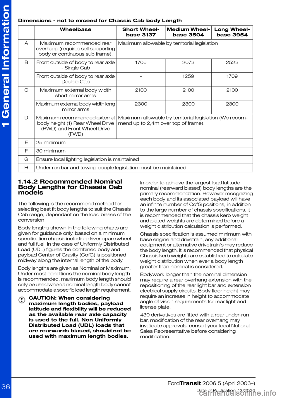
Dimensions - not to exceed for Chassis Cab body Length
Long Wheel-
base 3954
Medium Wheel-
base 3504
Short Wheel-
base 3137
Wheelbase
Maximum allowable by territorial legislationMaximum recommended rear
overhang (requires self supporting
body or continuous sub frame).
A
252320731706Front outside of body to rear axle
- Single Cab
B
17091259-Front outside of body to rear axle
Double Cab
210021002100Maximum external body width
short mirror arms
C
230023002300Maximum external body width long
mirror arms
Maximum allowable by territorial legislation (We recom-
mend up to 2,4m over top of frame).
Maximum recommended external
body height (1) Rear Wheel Drive
(RWD) and Front Wheel Drive
(FWD)
D
25 minimumE
30 minimumF
Ensure local lighting legislation is maintainedG
Under run bar and towing couple legislation must be maintainedH
1.14.2 Recommended Nominal
Body Lengths for Chassis Cab
models
The following is the recommend method for
selecting best fit body lengths to suit the Chassis
Cab range, dependant on the load biases of the
conversion
Body lengths shown in the following charts are
given for guidance only, based on a minimum
specification chassis including driver, spare wheel
and full fuel. In the case of Uniformly Distributed
Load (UDL) figures the combined body and
payload Center of Gravity (CofG) is positioned
midway along the internal length of the body.
Body lengths are given as Nominal or Maximum.
Under most conditions the nominal body length
is recommended, maximum body length should
only be used when a nominal length body cannot
accommodate a specific load length requirement.
CAUTION: When considering
maximum length bodies, payload
latitude and flexibility will be reduced
as the available rear axle capacity
is used to the full. Non Uniformly
Distributed Load (UDL) loads that
are rearwards biased, should not be
used with maximum length bodies.
In order to achieve the largest load latitude
nominal (rearward biased) body lengths are the
primary recommendation. However recognizing
each body and its associated payload will have
an infinite number of CofG positions, in addition
to the large number of chassis specifications, it
is recommended that the chassis kerb weight
and plated weights are determined before a
weight distribution calculation is performed.
Chassis specification is assumed minimum with
base engine and drivetrain, any additional
equipment or alternative drivetrain's may reduce
the body length. It is recommended that physical
Chassis kerb weights are established to calculate
weight distribution when ever a body length
greater than nominal is considered.
Bodywork longer than the nominal dimension
may require a rear overhang extension with the
repositioning of the rear light bar and extension
electrical supply circuits. Body floor height may
require an increase in height to accommodate
angle of vision requirements for rear light and
license plate.
430 derivatives are fitted with a rear under-run
bar, modification of the rear overhang may
invalidate approvals, consult your local National
Sales Representative before considering
modification.
FordTransit 2006.5 (April 2006–)
Date of Publication: 12/2006
1 General Information
36
Page 37 of 234
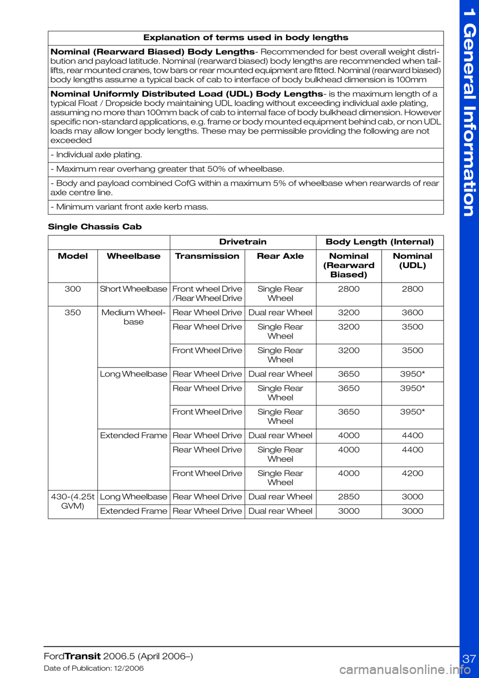
Explanation of terms used in body lengths
Nominal (Rearward Biased) Body Lengths- Recommended for best overall weight distri-
bution and payload latitude. Nominal (rearward biased) body lengths are recommended when tail-
lifts, rear mounted cranes, tow bars or rear mounted equipment are fitted. Nominal (rearward biased)
body lengths assume a typical back of cab to interface of body bulkhead dimension is 100mm
Nominal Uniformly Distributed Load (UDL) Body Lengths- is the maximum length of a
typical Float / Dropside body maintaining UDL loading without exceeding individual axle plating,
assuming no more than 100mm back of cab to internal face of body bulkhead dimension. However
specific non-standard applications, e.g. frame or body mounted equipment behind cab, or non UDL
loads may allow longer body lengths. These may be permissible providing the following are not
exceeded
- Individual axle plating.
- Maximum rear overhang greater that 50% of wheelbase.
- Body and payload combined CofG within a maximum 5% of wheelbase when rearwards of rear
axle centre line.
- Minimum variant front axle kerb mass.
Single Chassis Cab
Body Length (Internal)Drivetrain
Nominal
(UDL)
Nominal
(Rearward
Biased)
Rear AxleTransmissionWheelbaseModel
28002800Single Rear
Wheel
Front wheel Drive
/Rear Wheel Drive
Short Wheelbase300
36003200Dual rear WheelRear Wheel DriveMedium Wheel-
base
350
35003200Single Rear
Wheel
Rear Wheel Drive
35003200Single Rear
Wheel
Front Wheel Drive
3950*3650Dual rear WheelRear Wheel DriveLong Wheelbase
3950*3650Single Rear
Wheel
Rear Wheel Drive
3950*3650Single Rear
Wheel
Front Wheel Drive
44004000Dual rear WheelRear Wheel DriveExtended Frame
44004000Single Rear
Wheel
Rear Wheel Drive
42004000Single Rear
Wheel
Front Wheel Drive
30002850Dual rear WheelRear Wheel DriveLong Wheelbase430-(4.25t
GVM)30003000Dual rear WheelRear Wheel DriveExtended Frame
FordTransit 2006.5 (April 2006–)
Date of Publication: 12/2006
1 General Information
37