wiring FORD TRANSIT 2006 7.G Body And Equipment Mounting Section Manual
[x] Cancel search | Manufacturer: FORD, Model Year: 2006, Model line: TRANSIT, Model: FORD TRANSIT 2006 7.GPages: 234, PDF Size: 33.19 MB
Page 4 of 234
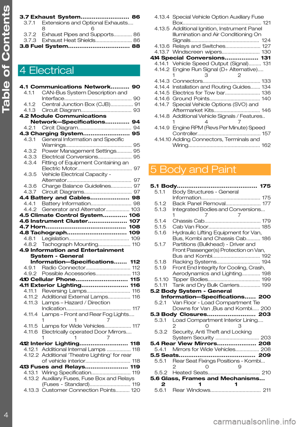
3.7Exhaust System..........................86
3.7.1Extensions and Optional Exhausts....
86
3.7.2Exhaust Pipes and Supports.............86
3.7.3Exhaust Heat Shields..........................86
3.8Fuel System.................................88
4 Electrical
4.1Communications Network..........90
4.1.1CAN-Bus System Description and
Interface................................................90
4.1.2Central Junction Box (CJB)................91
4.1.3Circuit Diagram....................................93
4.2Module Communications
Network—Specifications.............94
4.2.1Circit Diagram......................................94
4.3Charging System.........................95
4.3.1General Information and Specific
Warnings...............................................95
4.3.2Power Management Settings...........95
4.3.3Electrical Conversions........................95
4.3.4Fitting of Equipment Containing an
Electric Motor.......................................97
4.3.5Vehicle Electrical Capacity -
Alternator..............................................97
4.3.6Charge Balance Guidelines...............97
4.3.7Circuit Diagrams..................................97
4.4Battery and Cables.....................98
4.4.1Battery Information.............................98
4.4.2Generator and Alternator.................103
4.5Climate Control System.............106
4.6Instrument Cluster.....................107
4.7Horn...........................................108
4.8Tachograph................................109
4.8.1Legislation...........................................109
4.8.2Tachograph Mounting.......................110
4.9Information and Entertainment
System - General
Information—Specifications.......112
4.9.1Radio Connector................................112
4.9.2Possible Accessories.........................113
4.10Cellular Phone............................115
4.11Exterior Lighting.........................116
4.11.1Reversing Lamps...............................116
4.11.2Additional External Lamps................116
4.11.3Lamps – Hazard / Direction
Indication..............................................117
4.11.4Lamps – Front and Rear Fog Lights....
117
4.11.5Lamps for Wide Vehicles...................117
4.11.6Electrically operated Door Mirrors....
117
4.12Interior Lighting..........................118
4.12.1Additional Internal Lamps .................118
4.12.2Additional 'Theatre Lighting' for rear
of vehicle interior................................118
4.13Fuses and Relays.......................119
4.13.1Wiring Specification............................119
4.13.2Auxiliary Fuses, Fuse Box and Relays
(Fuses - Standard).............................119
4.13.3Customer Connection Points..........120
4.13.4Special Vehicle Option Auxiliary Fuse
Box........................................................121
4.13.5Additional Ignition, Instrument Panel
Illumination and Air Conditioning On
Signals.................................................124
4.13.6Relays and Switches.........................127
4.13.7Windscreen wipers...........................130
4.14Special Conversions..................131
4.14.1Vehicle Speed Output (Signal).........131
4.14.2Engine Run Signal (D+ Alternative)....
132
4.14.3Connectors.........................................133
4.14.4Installation and Routing Guides.......134
4.14.5Electrics for Tow bar.........................136
4.14.6Ground Points....................................140
4.14.7Special Vehicle Options (SVO) and
Aftermarket Kits.................................146
4.14.8Additional Vehicle Signals / Features..
147
4.14.9Engine RPM (Revs Per Minute) Speed
Controller.............................................157
4.14.10Adding Connectors, Terminals and
Wiring...................................................162
5 Body and Paint
5.1Body...........................................175
5.1.1Body Structures - General
Information..........................................175
5.1.2Back Panel Removal.........................177
5.1.3Integrated Bodies and Conversions...
177
5.1.4Chassis Cab........................................179
5.1.5Cab Van Floor.....................................185
5.1.6Hydraulic Lifting Equipment for Van,
Bus, Kombi and Chassis Cab..........186
5.1.7Partitions (Bulkhead) - Driver and
Front Passenger(s) Protection on Van,
Bus and Kombi..................................192
5.1.8Racking Systems...............................194
5.1.9Front End Integrity for Cooling, Crash,
Aerodynamics and Lighting.............198
5.1.10Tipper Bodies.....................................199
5.1.11Tank and Dry Bulk Carriers...............199
5.2Body System - General
Information—Specifications......200
5.2.1Van Floor - Load Compartment Tie
Downs for Van ,Bus and Kombi.....200
5.3Body Closures..........................203
5.3.1Load Compartment Interior Lining....
203
5.3.2Security, Anti Theft and Locking
System Security ...............................203
5.4Rear View Mirrors.....................208
5.4.1Mirrors for Wide Vehicles.................208
5.5Seats.........................................209
5.5.1Rear Seat Fixings Positions - Kombi...
209
5.5.2Heated Seats.....................................210
5.6Glass, Frames and Mechanisms...
211
5.6.1Rear Windows....................................211
Table of Contents
4
Page 24 of 234
1.6 Electromagnetic Compatibility (EMC)
The base vehicle has been tested and certified
to all relevant legislation relating to
Electromagnetic Compatibility. All retrofitted
equipment must also comply with the relevant
legislation.
In addition, 2-way radio communication and other
equipment with built in radio transmitters (for
example anti-theft alarms, tracking devices)
should only be fitted to the vehicle if they operate
within the listed frequency bands and do not
exceed the maximum transmission output power
specified below
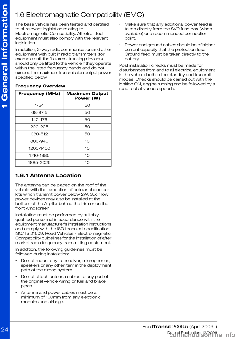
Frequency Overview
Maximum Output
Power (W)
Frequency (MHz)
501-54
5068-87.5
50142-176
50220-225
50380-512
10806-940
101200-1400
101710-1885
101885-2025
1.6.1 Antenna Location
The antenna can be placed on the roof of the
vehicle with the exception of cellular phone car
kits which transmit power below 2W. Such low
power devices may also be installed at the
bottom of the A-pillar behind the trim or on the
front windscreen.
Installation must be performed by suitably
qualified personnel in accordance with the
equipment manufacturer's installation instructions
and comply with the ISO technical specification
ISO/TS 21609: Road Vehicles - Electromagnetic
Compatibility guidelines for the installation of after
market radio frequency transmitting equipment.
In addition, the following guidelines must be
followed during installation:
•Do not mount any transceiver, microphones,
speakers or any other item in the deployment
path of the airbag system.
•Do not attach antenna cables to any part of
the original vehicle wiring or fuel and brake
pipes.
•Antenna and power cables must be a
minimum of 100mm from any electronic
modules and airbags.
•Make sure that any additional power feed is
taken directly from the SVO fuse box (when
available) or a recommended connection
point.
•Power and ground cables should be of higher
current capacity that the protection fuse.
Ground feed must be taken directly to the
battery.
Post installation checks must be made for
disturbances from and to all electrical equipment
in the vehicle both in the standby and transmit
modes. Checks should be carried out with the
ignition ON, engine running and be followed by a
road test at various speeds.
FordTransit 2006.5 (April 2006–)
Date of Publication: 12/2006
1 General Information
24
Page 63 of 234
2.7 Parking Brake
WARNINGS:
Do not modify the brakes
Do not splice into the parking brake
cable
CAUTION: Make sure that a new
parking brake cable is fitted if
modification to the wheelbase
impacts the existing parking brake
cable.
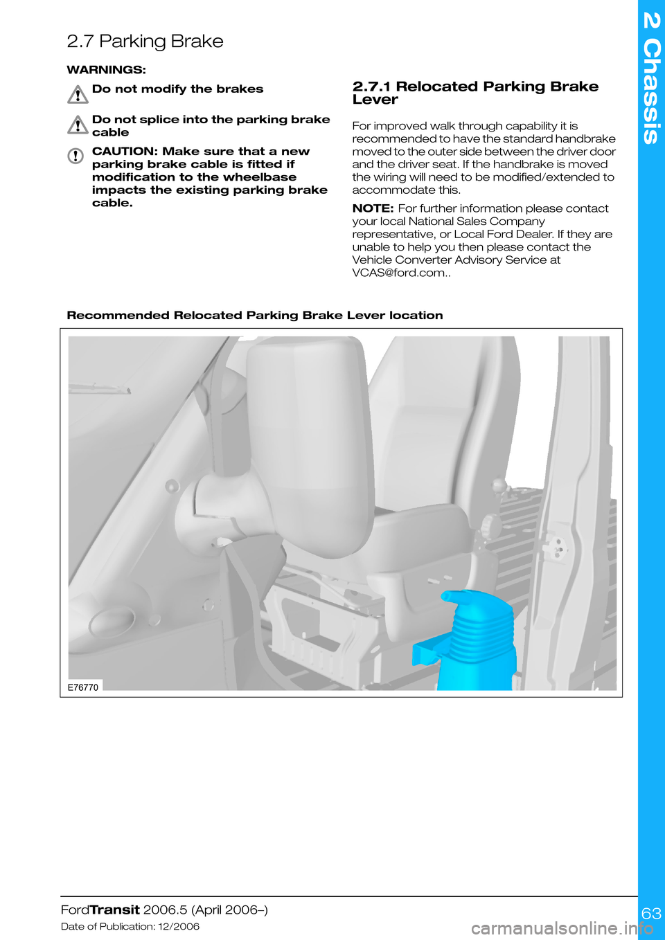
2.7.1 Relocated Parking Brake
Lever
For improved walk through capability it is
recommended to have the standard handbrake
moved to the outer side between the driver door
and the driver seat. If the handbrake is moved
the wiring will need to be modified/extended to
accommodate this.
NOTE: For further information please contact
your local National Sales Company
representative, or Local Ford Dealer. If they are
unable to help you then please contact the
Vehicle Converter Advisory Service at
[email protected]..
Recommended Relocated Parking Brake Lever location
FordTransit 2006.5 (April 2006–)
Date of Publication: 12/2006
2 Chassis
63E76770
Page 75 of 234
3.2 Engine Cooling
3.2.1 Auxiliary Heater Systems
WARNINGS:
Ford coolant additives are
necessary for the complete function
of the system. Only use ford
approved or equivalent specification
component, to withstand any
detrimental effects on the materials.
Do not mount components in front
of the grille or in an area of air flow
around the engine, which could
affect the engine cooling.
CAUTIONS:
Only make connections into the
heater hose between the front cab
heater and water pump return inlet.
Do not exceed the vehicle's original
coolant volume by more than 10%
Only use the manufactures
recommended (or equivalent
specification) coolant
additives/anti-freeze. Do not mix
coolant types.
•Coolant flow to cab heater must have priority
over flow to auxiliary heater or hand wash
facility.
•Coolant tube routing must be below the base
of the degas bottle.
•Use aluminum or plastic tee junction with
swaged or beaded ends to prevent hose blow
off. Reconnect original coolant tube as shown
in view E74570 (in this section) with standard
Ford water hose clip or suitable equivalent
specification clip. Ensure interference fit
between hose and 'T' joint.
•Tube routing must be secured to the body
structure or suitable brackets avoiding
electrical components or wires, hot or moving
parts and brake or fuel system components
•Hose must be heat sleeved with appropriate
material if within 100mm of exhaust
components (for example, manifold or
exhaust gas recirculating).
•The vertical clearance between the critical
cooling components (radiator, fan shroud and
radiator brackets) and both the hood inner
and outer (assembly) panels at design position
shall not be less than 15mm.
•There shall be a minimum clearance of 7mm
between the engine assembly and flexible
components (for example, hoses or wiring
harnesses) affixed to front end sheet metal
hardware, under a maximum engine torque
roll condition.
NOTE: For further information please contact
your local National Sales Company
representative, or Local Ford Dealer. If they are
unable to help you then please contact the
Vehicle Converter Advisory service at
[email protected].
FordTransit 2006.5 (April 2006–)
Date of Publication: 12/2006
3 Powertrain
75
Page 90 of 234
4.1 Communications Network
4.1.1 CAN-Bus System Description
and Interface
WARNING: Do not tamper with, cut
into or connect to any of the
CAN-Bus interface wiring or
connectors. The addition of
unapproved CAN-Based modules
could impact the safe operation of
the vehicle.
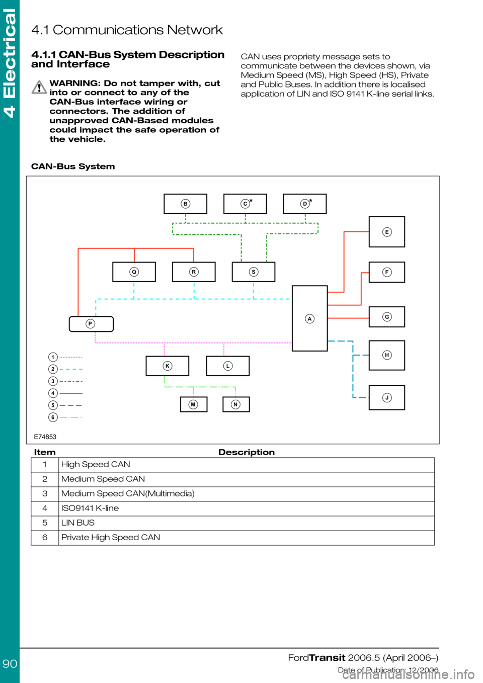
CAN uses propriety message sets to
communicate between the devices shown, via
Medium Speed (MS), High Speed (HS), Private
and Public Buses. In addition there is localised
application of LIN and ISO 9141 K-line serial links.
CAN-Bus System
DescriptionItem
High Speed CAN1
Medium Speed CAN2
Medium Speed CAN(Multimedia)3
ISO9141 K-line4
LIN BUS5
Private High Speed CAN6
FordTransit 2006.5 (April 2006–)
Date of Publication: 12/2006
4 Electrical
90BQP1RSLKMNEFGHJA23456E74853
Page 91 of 234
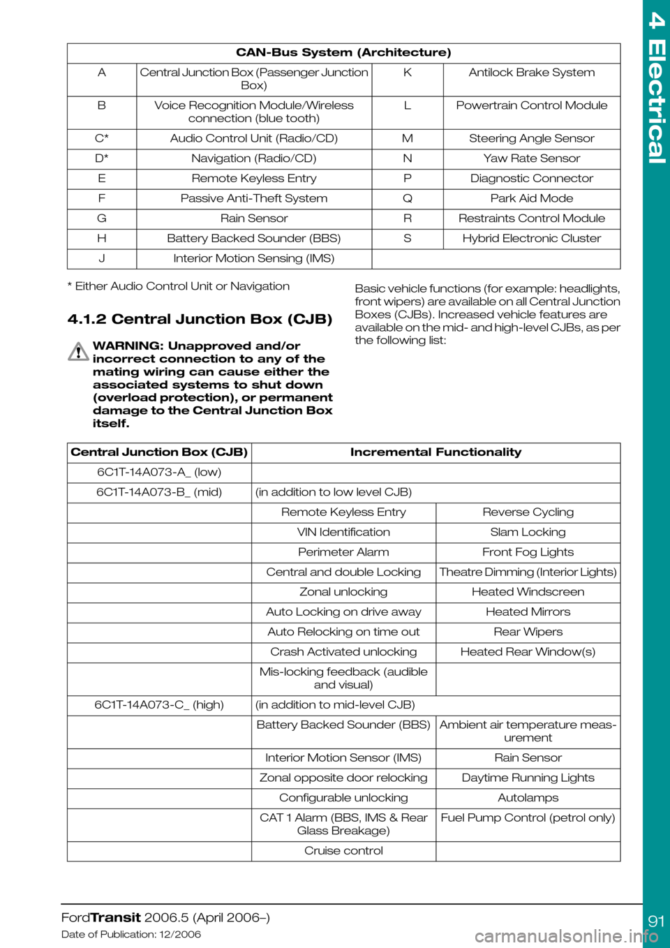
CAN-Bus System (Architecture)
Antilock Brake SystemKCentral Junction Box (Passenger Junction
Box)
A
Powertrain Control ModuleLVoice Recognition Module/Wireless
connection (blue tooth)
B
Steering Angle SensorMAudio Control Unit (Radio/CD)C*
Yaw Rate SensorNNavigation (Radio/CD)D*
Diagnostic ConnectorPRemote Keyless EntryE
Park Aid ModeQPassive Anti-Theft SystemF
Restraints Control ModuleRRain SensorG
Hybrid Electronic ClusterSBattery Backed Sounder (BBS)H
Interior Motion Sensing (IMS)J
* Either Audio Control Unit or Navigation
4.1.2 Central Junction Box (CJB)
WARNING: Unapproved and/or
incorrect connection to any of the
mating wiring can cause either the
associated systems to shut down
(overload protection), or permanent
damage to the Central Junction Box
itself.
Basic vehicle functions (for example: headlights,
front wipers) are available on all Central Junction
Boxes (CJBs). Increased vehicle features are
available on the mid- and high-level CJBs, as per
the following list:
Incremental FunctionalityCentral Junction Box (CJB)
6C1T-14A073-A_ (low)
(in addition to low level CJB)6C1T-14A073-B_ (mid)
Reverse CyclingRemote Keyless Entry
Slam LockingVIN Identification
Front Fog LightsPerimeter Alarm
Theatre Dimming (Interior Lights)Central and double Locking
Heated WindscreenZonal unlocking
Heated MirrorsAuto Locking on drive away
Rear WipersAuto Relocking on time out
Heated Rear Window(s)Crash Activated unlocking
Mis-locking feedback (audible
and visual)
(in addition to mid-level CJB)6C1T-14A073-C_ (high)
Ambient air temperature meas-
urement
Battery Backed Sounder (BBS)
Rain SensorInterior Motion Sensor (IMS)
Daytime Running LightsZonal opposite door relocking
AutolampsConfigurable unlocking
Fuel Pump Control (petrol only)CAT 1 Alarm (BBS, IMS & Rear
Glass Breakage)
Cruise control
FordTransit 2006.5 (April 2006–)
Date of Publication: 12/2006
4 Electrical
91
Page 93 of 234
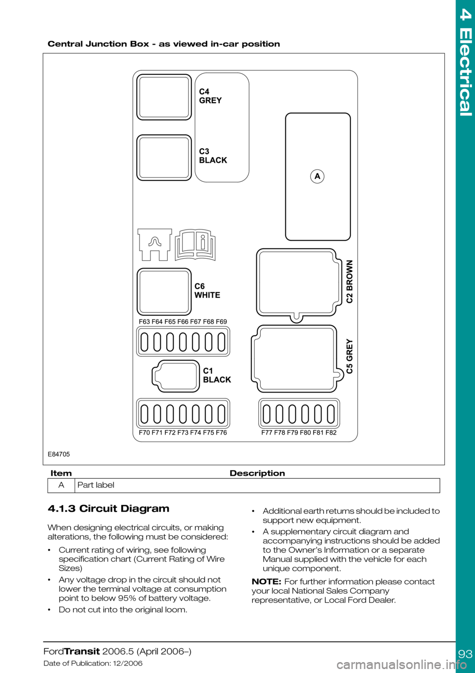
Central Junction Box - as viewed in-car position
DescriptionItem
Part labelA
4.1.3 Circuit Diagram
When designing electrical circuits, or making
alterations, the following must be considered:
•Current rating of wiring, see following
specification chart (Current Rating of Wire
Sizes)
•Any voltage drop in the circuit should not
lower the terminal voltage at consumption
point to below 95% of battery voltage.
•Do not cut into the original loom.
•Additional earth returns should be included to
support new equipment.
•A supplementary circuit diagram and
accompanying instructions should be added
to the Owner’s Information or a separate
Manual supplied with the vehicle for each
unique component.
NOTE: For further information please contact
your local National Sales Company
representative, or Local Ford Dealer.
FordTransit 2006.5 (April 2006–)
Date of Publication: 12/2006
4 Electrical
93E84705
Page 97 of 234
•Before disconnecting the battery, check
availability of radio key code.
•Fuses – when auxiliary electrical systems are
to be added to the vehicle it is mandatory that
the additional circuit design includes the
necessary fuses.
•The Special Vehicle Option auxiliary fuse box
is recommended.
Refer to: 4.13 Fuses and Relays (page 119).
4.3.4 Fitting of Equipment
Containing an Electric Motor
WARNINGS:
When equipment containing an
electrical motor is connected, it
must be connected via a blocking
diode or relay to prevent “back
Electro Motive Force (EMF)” being
applied to the auxiliary terminal.
When electric motors are to be
fitted, account must be taken of the
potentially high currents that a
motor can draw.
CAUTION: The following must be
observed:
•All motors must be driven via relays with
contacts rated at least 3 times the maximum
rated current of the motor.
•All motor supply circuits must be individually
fused with the proper fuse rating for the
motor.
•All power wiring must be rated for at least 3
times the rating of the motor and installed as
far away as possible from any existing vehicle
wiring.
•All motors fitted should be fully suppressed to
ensure electrical interference does not affect
the vehicle systems.
•Add EMC emissions statement to CE
approval.
4.3.5 Vehicle Electrical Capacity
- Alternator
WARNING: Do not cut into the
alternator wires or use the
alternator as a source to obtain a
'D+ Signal'
An engine run signal is available from the Central
Junction Box by installing a T-piece jumper
harness (Ford Part Number 6C1V-14A411-F_).
Refer to: 4.14 Special Conversions (page 131).
4.3.6 Charge Balance Guidelines
The base vehicle is fitted with a 150A alternator.
It is recommended to conduct a charge balance
calculation in case the conversion comprises a
high number of electrical consumers or high
electrical consumption is expected.
4.3.7 Circuit Diagrams
For circuit diagrams for Auxiliary Fuse Box
Connections and Standard Ford relays.
Refer to: 4.13 Fuses and Relays (page 119).
Full vehicle wiring and circuit diagrams are in the
Ford Workshop Manual.
NOTE: For further information please contact
your local National Sales Company
representative, or Local Ford Dealer. If they are
unable to help you then please contact the
Vehicle Converter Advisory Service at
[email protected].
FordTransit 2006.5 (April 2006–)
Date of Publication: 12/2006
4 Electrical
97
Page 98 of 234
4.4 Battery and Cables
4.4.1 Battery Information
In order to protect the battery system from direct
ground shorts, a special fuse is incorporated into
the battery positive feed, in the pre-fuse box
under the driver’s seat.
This fuse is not repairable – use only a Ford
replacement part.
Where extra batteries are required on vehicles
with a single battery installation, the battery
disconnect switch (split charge relay) and
associated wiring/hardware — fitted as standard
to vehicles equipped with dual batteries — can
be added.
Batteries – Additional – Heavy Duty
High current consumption may require a
heavy-duty battery or an additional battery.
Factory fitted Special Vehicle Options are available
for heavy-duty and/or extra batteries with the
battery disconnect switch (split charge relay).
The batteries can be retrofitted.
See diagram E74522 - Battery disconnect switch
(split charge relay) circuit.
Deep Cycle Battery (not for use as
primary, start-relevant battery)
A Special Vehicle Option is available. Please
contact your local National Sales Company
representative for availability and details.
•The deep cycle battery is used in conjunction
with the battery disconnect switch (split charge
relay) in applications where power to ancillary
circuits would heavily discharge the main
vehicle battery(s).
•Installation should be under the driver's seat.
When the deep cycle battery is installed, the
battery disconnect switch (split charge relay)
must be used.
•When the Deep Cycle Battery is installed it is
recommended that the Special Vehicle Option
auxiliary fuse box is fed from the customer
connection points.
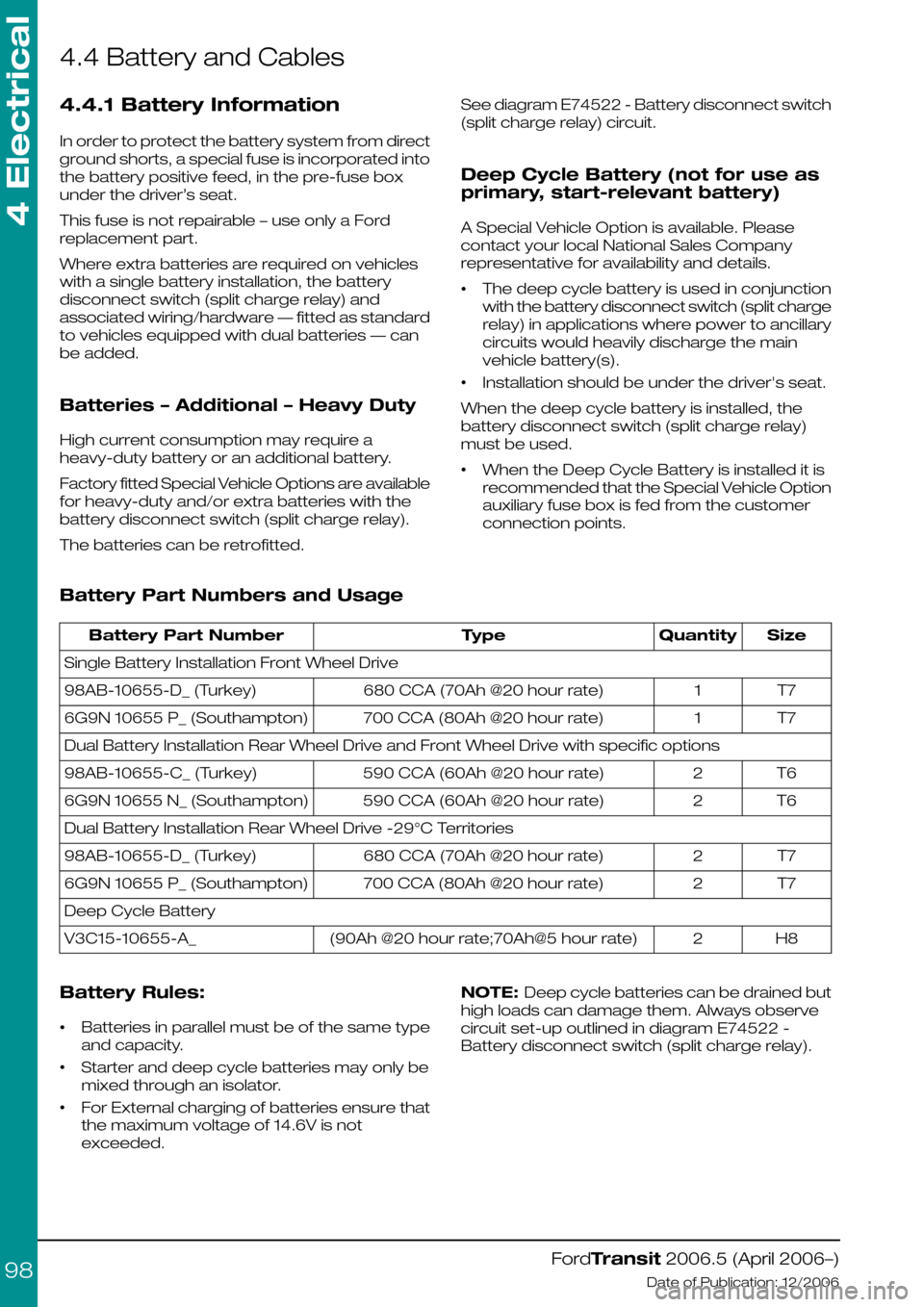
Battery Part Numbers and Usage
SizeQuantityTypeBattery Part Number
Single Battery Installation Front Wheel Drive
T71680 CCA (70Ah @20 hour rate)98AB-10655-D_ (Turkey)
T71700 CCA (80Ah @20 hour rate)6G9N 10655 P_ (Southampton)
Dual Battery Installation Rear Wheel Drive and Front Wheel Drive with specific options
T62590 CCA (60Ah @20 hour rate)98AB-10655-C_ (Turkey)
T62590 CCA (60Ah @20 hour rate)6G9N 10655 N_ (Southampton)
Dual Battery Installation Rear Wheel Drive -29°C Territories
T72680 CCA (70Ah @20 hour rate)98AB-10655-D_ (Turkey)
T72700 CCA (80Ah @20 hour rate)6G9N 10655 P_ (Southampton)
Deep Cycle Battery
H82(90Ah @20 hour rate;70Ah@5 hour rate)V3C15-10655-A_
Battery Rules:
•Batteries in parallel must be of the same type
and capacity.
•Starter and deep cycle batteries may only be
mixed through an isolator.
•For External charging of batteries ensure that
the maximum voltage of 14.6V is not
exceeded.
NOTE: Deep cycle batteries can be drained but
high loads can damage them. Always observe
circuit set-up outlined in diagram E74522 -
Battery disconnect switch (split charge relay).
FordTransit 2006.5 (April 2006–)
Date of Publication: 12/2006
4 Electrical
98
Page 100 of 234
Pull-in us actuvated within 70 ms of switching to
key position II
Pull-out is activated when switching to key
position I, or 0, and in key position II when no
engine run signal is sensed within 120 secs.
It is not possible to change state within 500 ms.
Removal of the Battery Disconnect
Switch (on twin battery models) and
wiring of batteries in parallel for high
current applications.
For vehicles equipped with a twin battery system,
wiring of the two batteries in parallel is not
recommended. If higher current is required,
680Ah batteries can be fitted (or a deep cycle
battery in lieu of the non-start relevant battery
only). Where a single passenger seat is fitted,
further batteries (1 or 2) can be installed in the
pedestal and added in parallel to the
non-start-relevant battery, although due
consideration then needs to be given to
increased current availability in the event of a
short circuit. Additional batteries should not be
installed under a passenger bench seat.
if this requirement is imperative, it would be
possible to disconnect the battery disconnect
switch and put the start-relevant and
non-start-relevant batteries in parallel using a
shorting bar (available from the Ford Delerships,
part number 6C1T-14A439-A*). There is one
important consideration when replacing the
battery disconnect switch with a shorting bar:
•Where the vehicle is configured for
twin-battery operation, the Central Junction
Box will detect if the battery disconnect switch
is missing (or has been removed), or the
mating connector short-circuited, and although
the vehicle will be functional, Diagnostic
Trouble Codes will be generated that will
flag-up during service. Hence if a shorting bar
is fitted, the vehicle needs to be reconfigured
(via the Dealership and Dealership Hotline).
Single to Dual Battery Conversion
For vehicles equipped with a single battery, it is
possible to upgrade to a twin battery system -
the connector for the battery disconnect switch
is present on all vehicles. In addition to
reconfiguring the vehicle for twin battery
operation (at a Dealership), the following battery
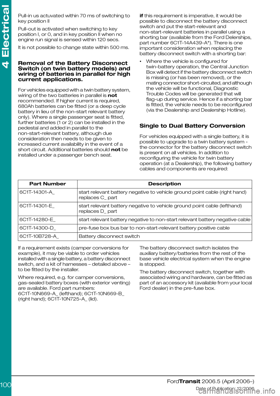
cables and components are required:
DescriptionPart Number
start relevant battery negative to vehicle ground point cable (right hand)
replaces C_ part
6C1T-14301-A_
start relevant battery negative to vehicle ground point cable (lefthand)
replaces D_ part
6C1T-14301-E_
start relevant battery negative to non-start relevant battery negative cable6C1T-14280-E_
pre-fuse box bus bar to non-start-relevant battery positive cable6C1T-14300-D_
Battery disconnect switch6C1T-10B728-A_
If a requirement exists (camper conversions for
example), it may be viable to order vehicles
installed with a single battery, a battery disconnect
switch, and a kit of harnesses – detailed above –
to be fitted by the installer.
Where required, e.g. for camper conversions,
gas-sealed battery boxes (with exterior venting)
are available. Ford part numbers:
6C1T-10N669-A_ (lefthand); 6C1T-10N669-B_
(right hand); 6C1T-10N725-A_ (lid).
The battery disconnect switch isolates the
auxiliary battery/batteries from the rest of the
base vehicle electrical system when the engine
is stopped.
The battery disconnect switch, together with
associated wiring and hardware, can be fitted as
part of an accessory kit (available from your local
Ford dealer) in the pre-fuse box.
FordTransit 2006.5 (April 2006–)
Date of Publication: 12/2006
4 Electrical
100