sensor FORD TRANSIT 2015 5.G Owner's Manual
[x] Cancel search | Manufacturer: FORD, Model Year: 2015, Model line: TRANSIT, Model: FORD TRANSIT 2015 5.GPages: 461, PDF Size: 5.82 MB
Page 155 of 461
Setting the System Sensitivity
You can adjust how quickly the system
warns you of a dangerous situation. The
system has two sensitivity levels which you
can set using the information display. See
(page 79).
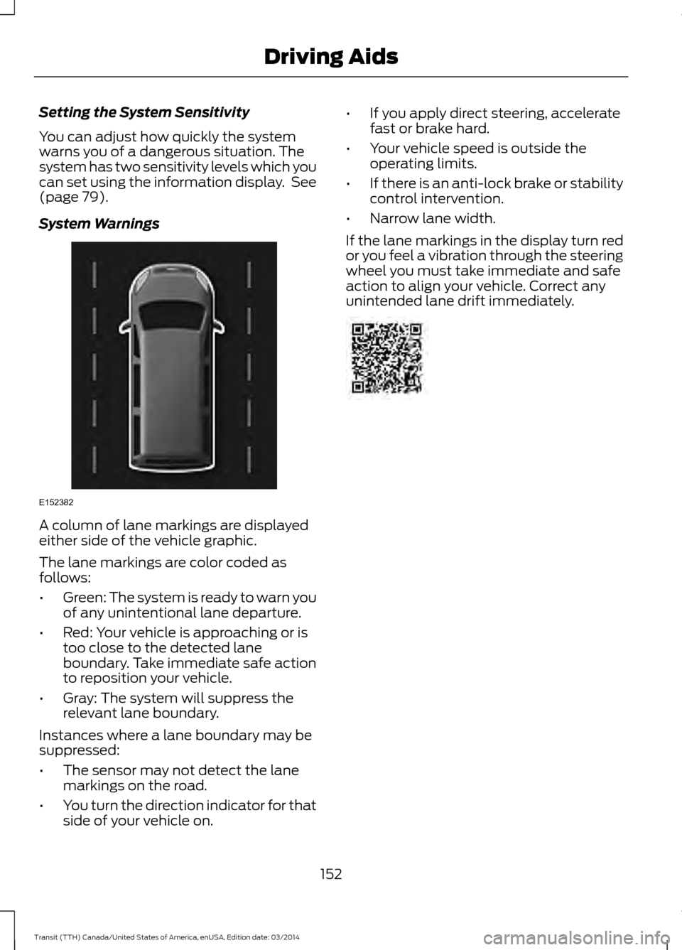
System Warnings A column of lane markings are displayed
either side of the vehicle graphic.
The lane markings are color coded as
follows:
•
Green: The system is ready to warn you
of any unintentional lane departure.
• Red: Your vehicle is approaching or is
too close to the detected lane
boundary. Take immediate safe action
to reposition your vehicle.
• Gray: The system will suppress the
relevant lane boundary.
Instances where a lane boundary may be
suppressed:
• The sensor may not detect the lane
markings on the road.
• You turn the direction indicator for that
side of your vehicle on. •
If you apply direct steering, accelerate
fast or brake hard.
• Your vehicle speed is outside the
operating limits.
• If there is an anti-lock brake or stability
control intervention.
• Narrow lane width.
If the lane markings in the display turn red
or you feel a vibration through the steering
wheel you must take immediate and safe
action to align your vehicle. Correct any
unintended lane drift immediately. 152
Transit (TTH) Canada/United States of America, enUSA, Edition date: 03/2014 Driving AidsE152382
Page 193 of 461
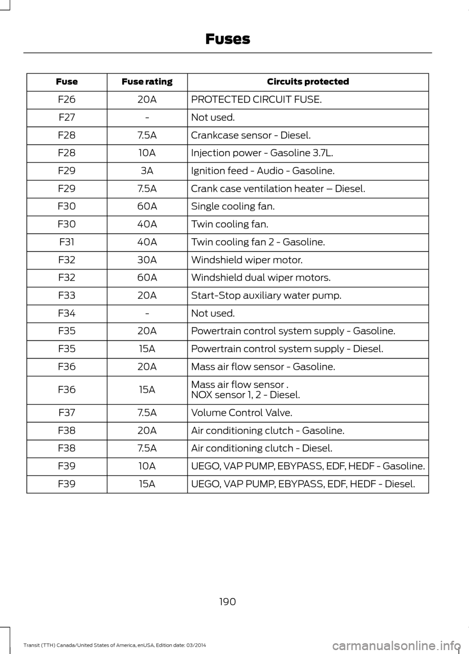
Circuits protected
Fuse rating
Fuse
PROTECTED CIRCUIT FUSE.
20A
F26
Not used.
-
F27
Crankcase sensor - Diesel.
7.5A
F28
Injection power - Gasoline 3.7L.
10A
F28
Ignition feed - Audio - Gasoline.
3A
F29
Crank case ventilation heater – Diesel.
7.5A
F29
Single cooling fan.
60A
F30
Twin cooling fan.
40A
F30
Twin cooling fan 2 - Gasoline.
40A
F31
Windshield wiper motor.
30A
F32
Windshield dual wiper motors.
60A
F32
Start-Stop auxiliary water pump.
20A
F33
Not used.
-
F34
Powertrain control system supply - Gasoline.
20A
F35
Powertrain control system supply - Diesel.
15A
F35
Mass air flow sensor - Gasoline.
20A
F36
Mass air flow sensor .
15A
F36
NOX sensor 1, 2 - Diesel.
Volume Control Valve.
7.5A
F37
Air conditioning clutch - Gasoline.
20A
F38
Air conditioning clutch - Diesel.
7.5A
F38
UEGO, VAP PUMP, EBYPASS, EDF, HEDF - Gasoline.
10A
F39
UEGO, VAP PUMP, EBYPASS, EDF, HEDF - Diesel.
15A
F39
190Transit (TTH) Canada/United States of America, enUSA, Edition date: 03/2014 Fuses
Page 200 of 461
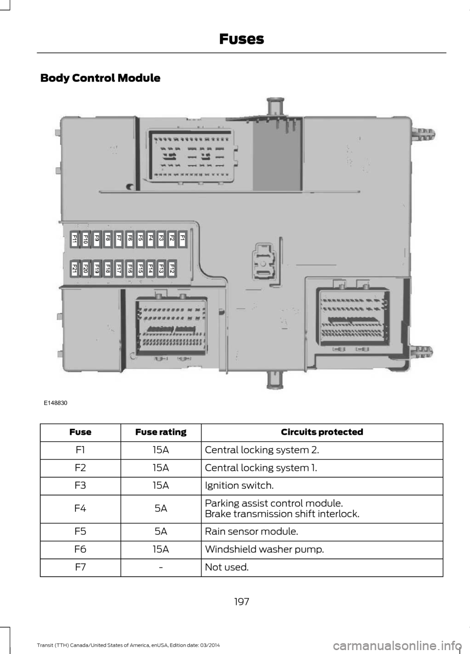
Body Control Module
Circuits protected
Fuse rating
Fuse
Central locking system 2.
15A
F1
Central locking system 1.
15A
F2
Ignition switch.
15A
F3
Parking assist control module.
5A
F4
Brake transmission shift interlock.
Rain sensor module.
5A
F5
Windshield washer pump.
15A
F6
Not used.
-
F7
197Transit (TTH) Canada/United States of America, enUSA, Edition date: 03/2014 FusesE148830
Page 201 of 461
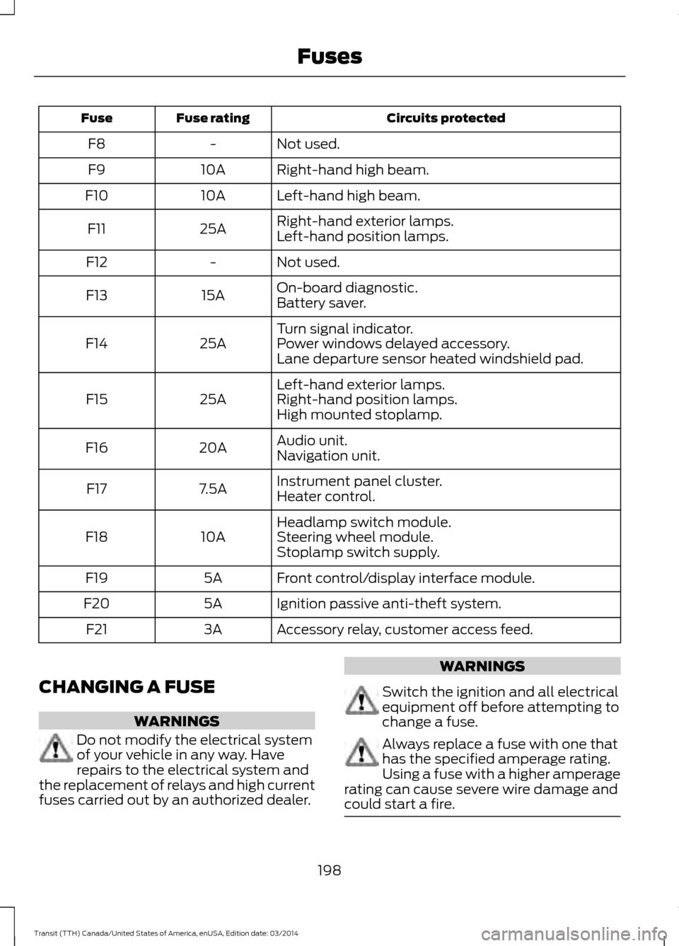
Circuits protected
Fuse rating
Fuse
Not used.
-
F8
Right-hand high beam.
10A
F9
Left-hand high beam.
10A
F10
Right-hand exterior lamps.
25A
F11
Left-hand position lamps.
Not used.
-
F12
On-board diagnostic.
15A
F13
Battery saver.
Turn signal indicator.
25A
F14 Power windows delayed accessory.
Lane departure sensor heated windshield pad.
Left-hand exterior lamps.
25A
F15 Right-hand position lamps.
High mounted stoplamp.
Audio unit.
20A
F16
Navigation unit.
Instrument panel cluster.
7.5A
F17
Heater control.
Headlamp switch module.
10A
F18 Steering wheel module.
Stoplamp switch supply.
Front control/display interface module.
5A
F19
Ignition passive anti-theft system.
5A
F20
Accessory relay, customer access feed.
3A
F21
CHANGING A FUSE WARNINGS
Do not modify the electrical system
of your vehicle in any way. Have
repairs to the electrical system and
the replacement of relays and high current
fuses carried out by an authorized dealer. WARNINGS
Switch the ignition and all electrical
equipment off before attempting to
change a fuse.
Always replace a fuse with one that
has the specified amperage rating.
Using a fuse with a higher amperage
rating can cause severe wire damage and
could start a fire. 198
Transit (TTH) Canada/United States of America, enUSA, Edition date: 03/2014 Fuses
Page 218 of 461
Install in the reverse order.
CHECKING THE WIPER
BLADES
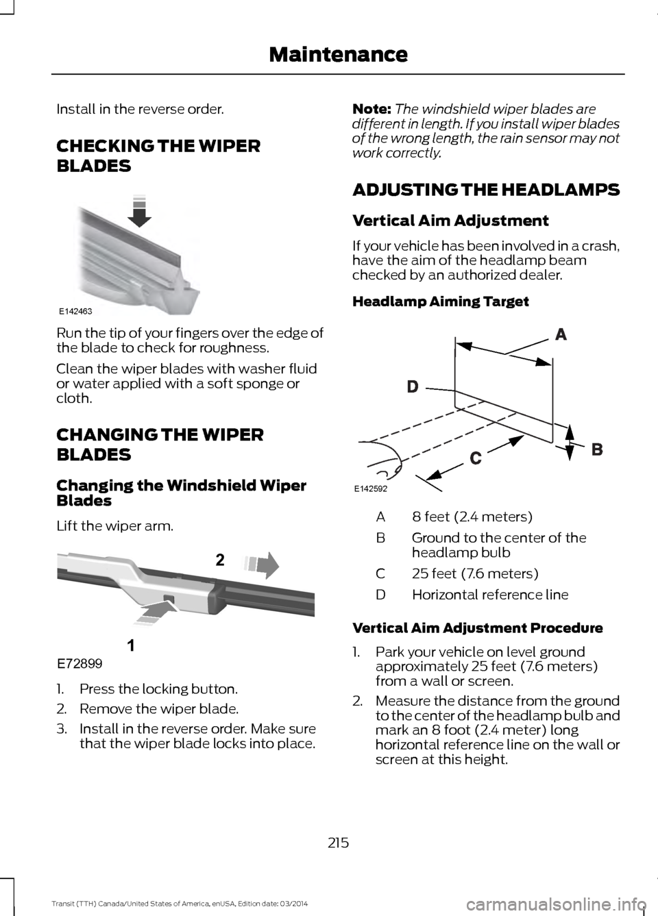
Run the tip of your fingers over the edge of
the blade to check for roughness.
Clean the wiper blades with washer fluid
or water applied with a soft sponge or
cloth.
CHANGING THE WIPER
BLADES
Changing the Windshield Wiper
Blades
Lift the wiper arm.
1. Press the locking button.
2. Remove the wiper blade.
3. Install in the reverse order. Make sure
that the wiper blade locks into place. Note:
The windshield wiper blades are
different in length. If you install wiper blades
of the wrong length, the rain sensor may not
work correctly.
ADJUSTING THE HEADLAMPS
Vertical Aim Adjustment
If your vehicle has been involved in a crash,
have the aim of the headlamp beam
checked by an authorized dealer.
Headlamp Aiming Target 8 feet (2.4 meters)
A
Ground to the center of the
headlamp bulb
B
25 feet (7.6 meters)
C
Horizontal reference line
D
Vertical Aim Adjustment Procedure
1. Park your vehicle on level ground approximately 25 feet (7.6 meters)
from a wall or screen.
2. Measure the distance from the ground
to the center of the headlamp bulb and
mark an 8 foot (2.4 meter) long
horizontal reference line on the wall or
screen at this height.
215 Transit (TTH) Canada/United States of America, enUSA, Edition date: 03/2014 MaintenanceE142463 E72899
1
2 E142592
Page 223 of 461
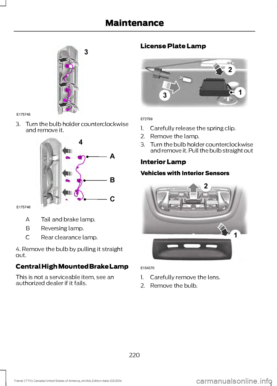
3.
Turn the bulb holder counterclockwise
and remove it. Tail and brake lamp.
A
Reversing lamp.
B
Rear clearance lamp.
C
4. Remove the bulb by pulling it straight
out.
Central High Mounted Brake Lamp
This is not a serviceable item, see an
authorized dealer if it fails. License Plate Lamp 1. Carefully release the spring clip.
2. Remove the lamp.
3.
Turn the bulb holder counterclockwise
and remove it. Pull the bulb straight out
Interior Lamp
Vehicles with Interior Sensors 1. Carefully remove the lens.
2. Remove the bulb.
220 Transit (TTH) Canada/United States of America, enUSA, Edition date: 03/2014 Maintenance3
E175745 A
B
C
4
E175746 3
2
1
E72789 1
2
E154370
Page 224 of 461
Reading Lamps
Vehicles with Interior Sensors
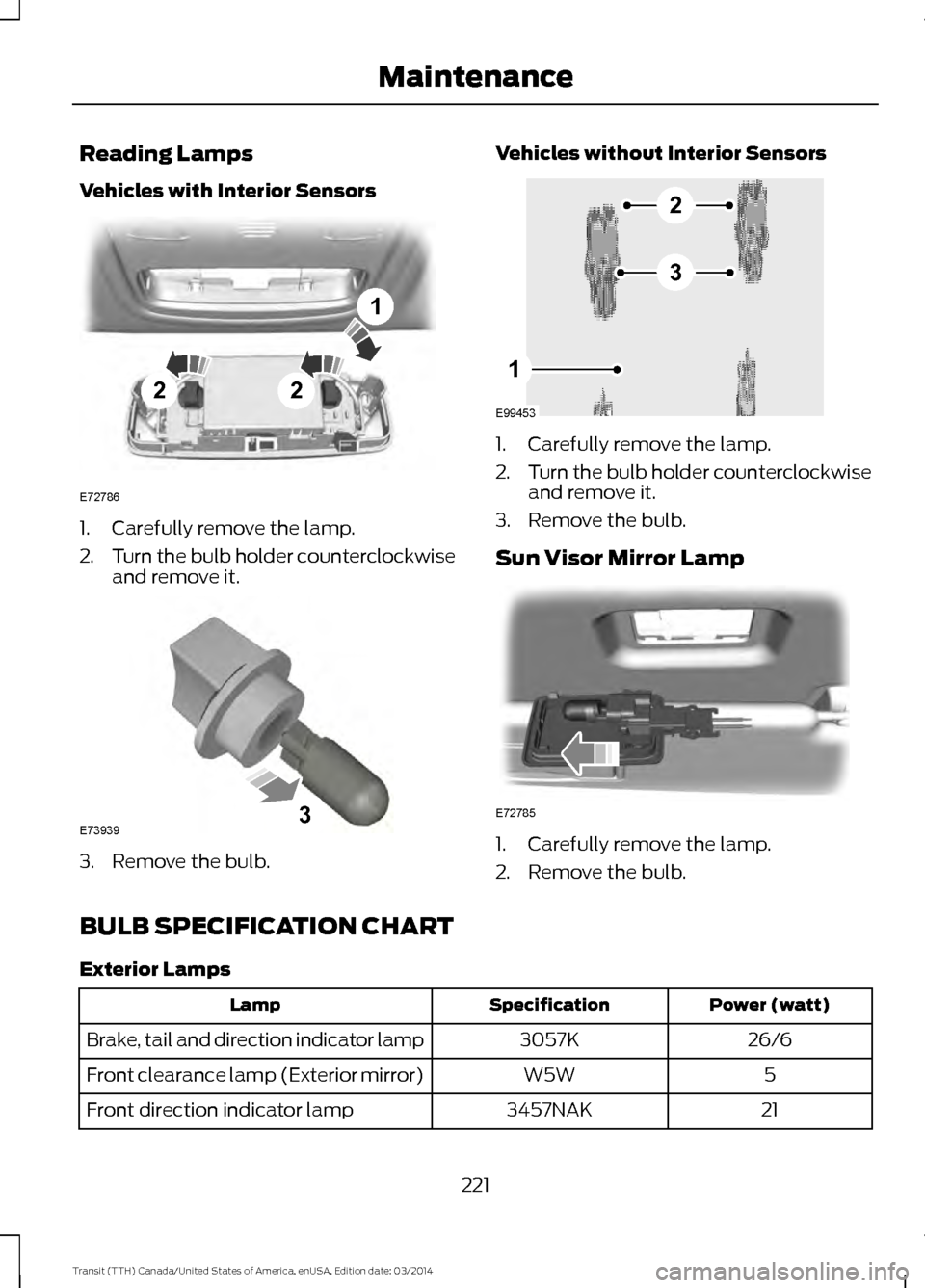
1. Carefully remove the lamp.
2.
Turn the bulb holder counterclockwise
and remove it. 3. Remove the bulb. Vehicles without Interior Sensors 1. Carefully remove the lamp.
2.
Turn the bulb holder counterclockwise
and remove it.
3. Remove the bulb.
Sun Visor Mirror Lamp 1. Carefully remove the lamp.
2. Remove the bulb.
BULB SPECIFICATION CHART
Exterior Lamps Power (watt)
Specification
Lamp
26/6
3057K
Brake, tail and direction indicator lamp
5
W5W
Front clearance lamp (Exterior mirror)
21
3457NAK
Front direction indicator lamp
221Transit (TTH) Canada/United States of America, enUSA, Edition date: 03/2014 Maintenance22
1
E72786 E739393 E99453
2
3
1 E72785
Page 226 of 461
CHANGING THE ENGINE AIR
FILTER - 3.5L
WARNING
To reduce the risk of vehicle damage
and personal burn injuries, do not
start your engine with the air cleaner
removed and do not remove it while the
engine is running. Note:
Failure to use the correct air filter
element may result in severe engine
damage. The vehicle warranty may be void
for any damage to the engine if the correct
air filter element is not used.
Only use the specified air filter. See
Capacities and Specifications (page
265).
Change the air filter element at the proper
interval.
See Scheduled Maintenance
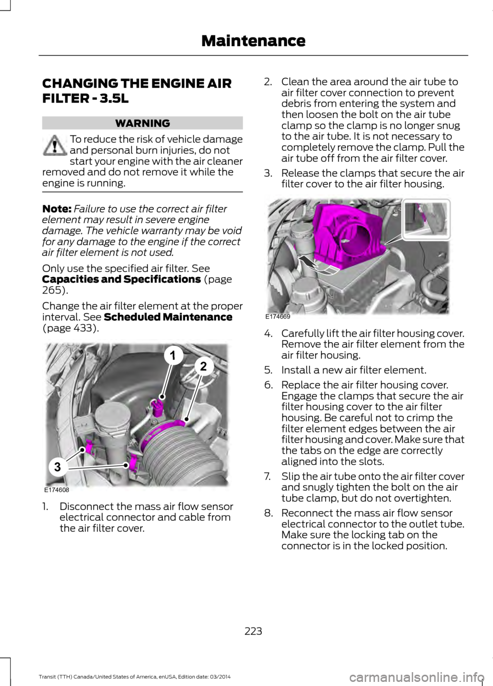
(page 433). 1. Disconnect the mass air flow sensor
electrical connector and cable from
the air filter cover. 2. Clean the area around the air tube to
air filter cover connection to prevent
debris from entering the system and
then loosen the bolt on the air tube
clamp so the clamp is no longer snug
to the air tube. It is not necessary to
completely remove the clamp. Pull the
air tube off from the air filter cover.
3. Release the clamps that secure the air
filter cover to the air filter housing. 4.
Carefully lift the air filter housing cover.
Remove the air filter element from the
air filter housing.
5. Install a new air filter element.
6. Replace the air filter housing cover. Engage the clamps that secure the air
filter housing cover to the air filter
housing. Be careful not to crimp the
filter element edges between the air
filter housing and cover. Make sure that
the tabs on the edge are correctly
aligned into the slots.
7. Slip the air tube onto the air filter cover
and snugly tighten the bolt on the air
tube clamp, but do not overtighten.
8. Reconnect the mass air flow sensor electrical connector to the outlet tube.
Make sure the locking tab on the
connector is in the locked position.
223 Transit (TTH) Canada/United States of America, enUSA, Edition date: 03/2014 MaintenanceE174608
12
3 E174669
Page 227 of 461
CHANGING THE ENGINE AIR
FILTER - 3.7L
WARNING
To reduce the risk of vehicle damage
and personal burn injuries, do not
start your engine with the air cleaner
removed and do not remove it while the
engine is running. Note:
Failure to use the correct air filter
element may result in severe engine
damage. The vehicle warranty may be void
for any damage to the engine if the correct
air filter element is not used.
Only use the specified air filter. See
Capacities and Specifications (page
265).
Change the air filter element at the proper
interval.
See Scheduled Maintenance
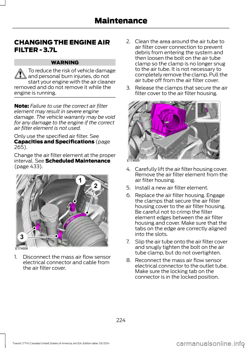
(page 433). 1. Disconnect the mass air flow sensor
electrical connector and cable from
the air filter cover. 2. Clean the area around the air tube to
air filter cover connection to prevent
debris from entering the system and
then loosen the bolt on the air tube
clamp so the clamp is no longer snug
to the air tube. It is not necessary to
completely remove the clamp. Pull the
air tube off from the air filter cover.
3. Release the clamps that secure the air
filter cover to the air filter housing. 4.
Carefully lift the air filter housing cover.
Remove the air filter element from the
air filter housing.
5. Install a new air filter element.
6. Replace the air filter housing. Engage the clamps that secure the air filter
housing cover to the air filter housing.
Be careful not to crimp the filter
element edges between the air filter
housing and cover. Make sure that the
tabs on the edge are correctly aligned
into the slots.
7. Slip the air tube onto the air filter cover
and snugly tighten the bolt on the air
tube clamp, but do not overtighten.
8. Reconnect the mass air flow sensor electrical connector to the outlet tube.
Make sure the locking tab on the
connector is in the locked position.
224 Transit (TTH) Canada/United States of America, enUSA, Edition date: 03/2014 MaintenanceE174608
12
3 E174669
Page 228 of 461
CHANGING THE ENGINE AIR
FILTER - 3.2L POWER STROKE
DIESEL
WARNING
To reduce the risk of vehicle damage
and personal burn injuries, do not
start your engine with the air cleaner
removed and do not remove it while the
engine is running. Note:
Failure to use the correct air filter
element may result in severe engine
damage. The vehicle warranty may be void
for any damage to the engine if the correct
air filter element is not used.
Note: After operating the vehicle up to
200 mi (320 km) in heavy snowfall, we
recommend that you open the hood at the
earliest opportunity and clear the snow and
ice from air filter housing. Do not remove the
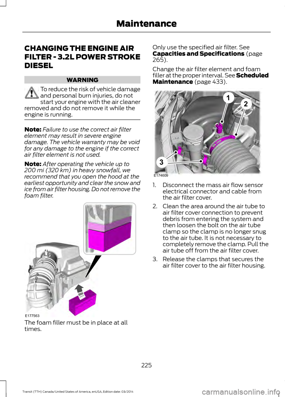
foam filter. The foam filler must be in place at all
times. Only use the specified air filter.
See
Capacities and Specifications (page
265).
Change the air filter element and foam
filler at the proper interval. See Scheduled
Maintenance
(page 433). 1. Disconnect the mass air flow sensor
electrical connector and cable from
the air filter cover.
2. Clean the area around the air tube to air filter cover connection to prevent
debris from entering the system and
then loosen the bolt on the air tube
clamp so the clamp is no longer snug
to the air tube. It is not necessary to
completely remove the clamp. Pull the
air tube off from the air filter cover.
3. Release the clamps that secures the air filter cover to the air filter housing.
225 Transit (TTH) Canada/United States of America, enUSA, Edition date: 03/2014 MaintenanceE177563 E174609
12
3