change wheel FORD TRANSIT 2016 5.G Owners Manual
[x] Cancel search | Manufacturer: FORD, Model Year: 2016, Model line: TRANSIT, Model: FORD TRANSIT 2016 5.GPages: 411, PDF Size: 5.65 MB
Page 7 of 411
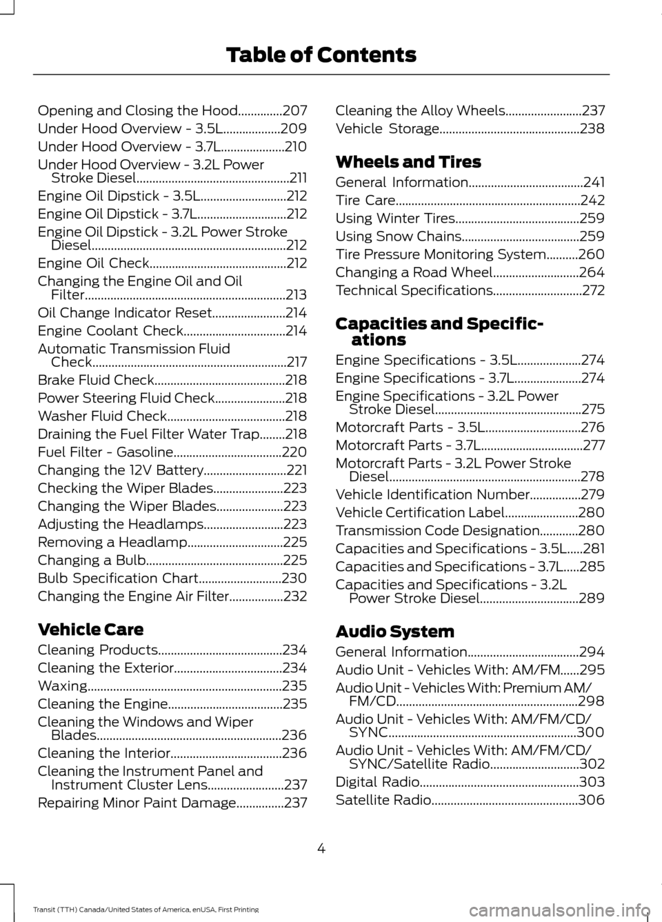
Opening and Closing the Hood..............207
Under Hood Overview - 3.5L..................209
Under Hood Overview - 3.7L....................210
Under Hood Overview - 3.2L Power
Stroke Diesel................................................211
Engine Oil Dipstick - 3.5L...........................212
Engine Oil Dipstick - 3.7L............................212
Engine Oil Dipstick - 3.2L Power Stroke Diesel.............................................................212
Engine Oil Check...........................................212
Changing the Engine Oil and Oil Filter...............................................................213
Oil Change Indicator Reset.......................214
Engine Coolant Check
................................214
Automatic Transmission Fluid Check.............................................................217
Brake Fluid Check.........................................218
Power Steering Fluid Check......................218
Washer Fluid Check
.....................................218
Draining the Fuel Filter Water Trap........218
Fuel Filter - Gasoline
..................................220
Changing the 12V Battery
..........................221
Checking the Wiper Blades......................223
Changing the Wiper Blades.....................223
Adjusting the Headlamps
.........................223
Removing a Headlamp
..............................225
Changing a Bulb...........................................225
Bulb Specification Chart
..........................230
Changing the Engine Air Filter.................232
Vehicle Care
Cleaning Products
.......................................234
Cleaning the Exterior..................................234
Waxing.............................................................235
Cleaning the Engine....................................235
Cleaning the Windows and Wiper Blades..........................................................236
Cleaning the Interior...................................236
Cleaning the Instrument Panel and Instrument Cluster Lens........................237
Repairing Minor Paint Damage...............237 Cleaning the Alloy Wheels
........................237
Vehicle Storage
............................................238
Wheels and Tires
General Information
....................................241
Tire Care
..........................................................242
Using Winter Tires.......................................259
Using Snow Chains.....................................259
Tire Pressure Monitoring System..........260
Changing a Road Wheel...........................264
Technical Specifications............................272
Capacities and Specific- ations
Engine Specifications - 3.5L....................274
Engine Specifications - 3.7L
.....................274
Engine Specifications - 3.2L Power Stroke Diesel..............................................275
Motorcraft Parts - 3.5L..............................276
Motorcraft Parts - 3.7L
................................277
Motorcraft Parts - 3.2L Power Stroke Diesel............................................................278
Vehicle Identification Number................279
Vehicle Certification Label.......................280
Transmission Code Designation............280
Capacities and Specifications - 3.5L.....281
Capacities and Specifications - 3.7L.....285
Capacities and Specifications - 3.2L Power Stroke Diesel...............................289
Audio System
General Information
...................................294
Audio Unit - Vehicles With: AM/FM......295
Audio Unit - Vehicles With: Premium AM/ FM/CD.........................................................298
Audio Unit - Vehicles With: AM/FM/CD/ SYNC...........................................................300
Audio Unit - Vehicles With: AM/FM/CD/ SYNC/Satellite Radio............................302
Digital Radio
..................................................303
Satellite Radio
..............................................306
4
Transit (TTH) Canada/United States of America, enUSA, First Printing Table of Contents
Page 54 of 411
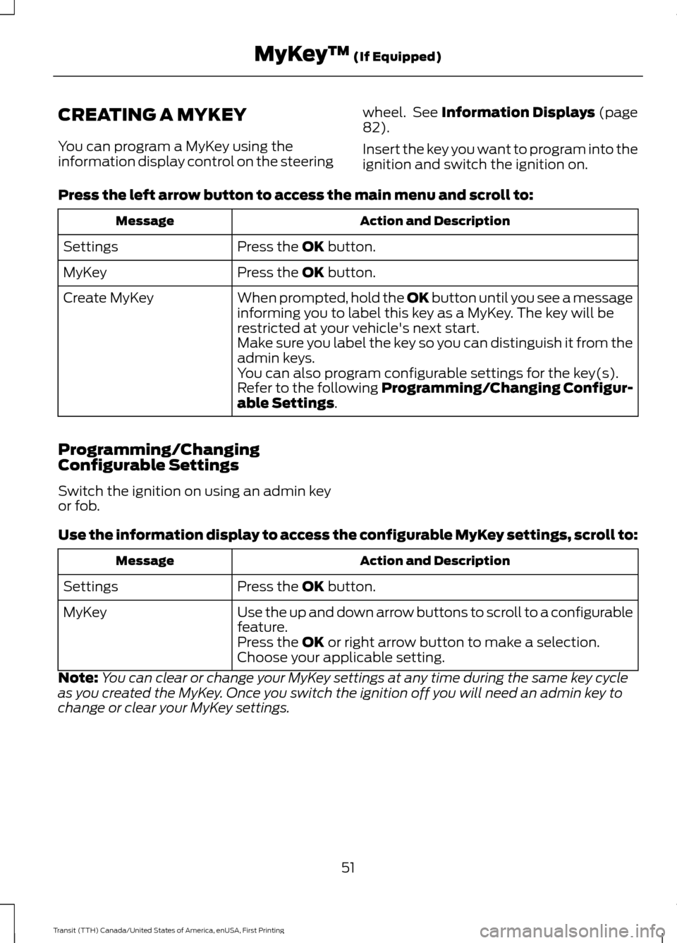
CREATING A MYKEY
You can program a MyKey using the
information display control on the steering
wheel. See Information Displays (page
82).
Insert the key you want to program into the
ignition and switch the ignition on.
Press the left arrow button to access the main menu and scroll to: Action and Description
Message
Press the
OK button.
Settings
Press the
OK button.
MyKey
When prompted, hold the OK button until you see a message
informing you to label this key as a MyKey. The key will be
restricted at your vehicle's next start.
Create MyKey
Make sure you label the key so you can distinguish it from the
admin keys.
You can also program configurable settings for the key(s).
Refer to the following Programming/Changing Configur-
able Settings
.
Programming/Changing
Configurable Settings
Switch the ignition on using an admin key
or fob.
Use the information display to access the configurable MyKey settings, scroll to: Action and Description
Message
Press the
OK button.
Settings
Use the up and down arrow buttons to scroll to a configurable
feature.
MyKey
Press the
OK or right arrow button to make a selection.
Choose your applicable setting.
Note: You can clear or change your MyKey settings at any time during the same key cycle
as you created the MyKey. Once you switch the ignition off you will need an admin key to
change or clear your MyKey settings.
51
Transit (TTH) Canada/United States of America, enUSA, First Printing MyKey
™
(If Equipped)
Page 55 of 411
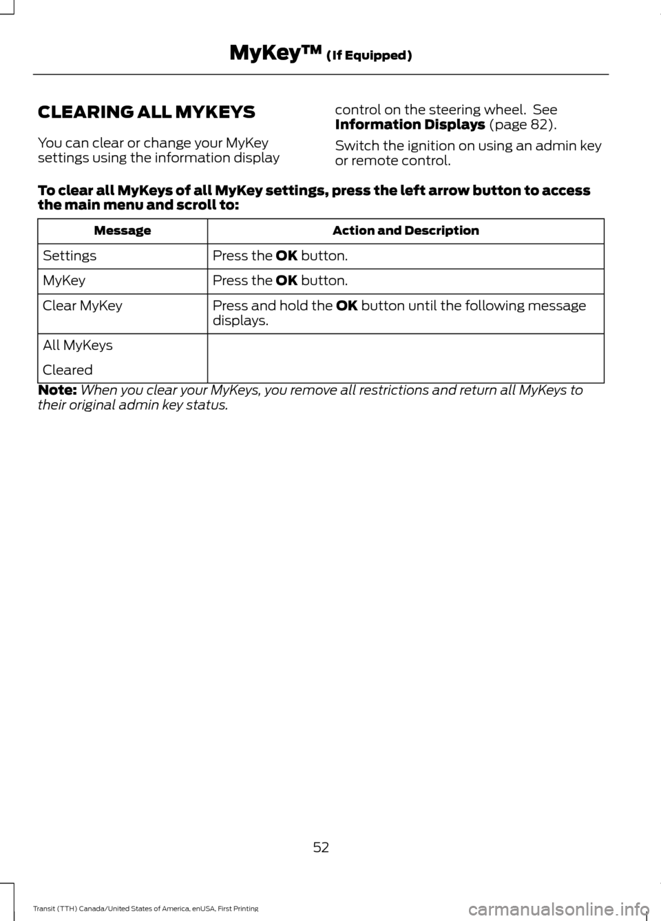
CLEARING ALL MYKEYS
You can clear or change your MyKey
settings using the information display
control on the steering wheel. See
Information Displays (page 82).
Switch the ignition on using an admin key
or remote control.
To clear all MyKeys of all MyKey settings, press the left arrow button to access
the main menu and scroll to: Action and Description
Message
Press the
OK button.
Settings
Press the
OK button.
MyKey
Press and hold the
OK button until the following message
displays.
Clear MyKey
All MyKeys
Cleared
Note: When you clear your MyKeys, you remove all restrictions and return all MyKeys to
their original admin key status.
52
Transit (TTH) Canada/United States of America, enUSA, First Printing MyKey
™
(If Equipped)
Page 89 of 411
System Check
All active warnings will display first if
applicable. The system check menu may
appear different based upon equipment
options and current vehicle status. Use the
up and down arrow buttons to scroll
through the list. See Information
Messages (page 87).
TRIP COMPUTER
Resetting the Trip Computer
Press and hold
OK on the current screen
to reset the respective trip, distance, time
and average fuel consumption information.
All Values
Indicates all the respective trip, distance,
time and average fuel consumption
information.
Average Fuel Consumption
Indicates the average fuel consumption
since the function was last reset. Distance to Empty
Indicates the approximate distance your
vehicle will travel on the fuel remaining in
the tank. Changes in driving pattern may
cause the value to vary.
Outside Air Temperature
Shows the outside air temperature.
Trip Odometer
Registers the distance traveled of
individual journeys.
Trip Timer
Registers the elapsed time of individual
journeys or the total time since the function
was last reset.
Digital Speedometer
Provides a digital display of the current
vehicle speed.
PERSONALIZED SETTINGS
Measure Units
You can choose personalized settings
using the information display control on
the steering wheel.
See Information
Displays (page 82).
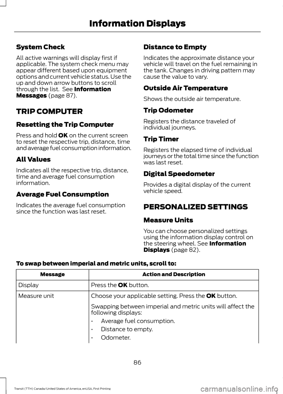
To swap between imperial and metric units, scroll to: Action and Description
Message
Press the
OK button.
Display
Choose your applicable setting. Press the
OK button.
Measure unit
Swapping between imperial and metric units will affect the
following displays:
•Average fuel consumption.
• Distance to empty.
• Odometer.
86
Transit (TTH) Canada/United States of America, enUSA, First Printing Information Displays
Page 147 of 411
PRINCIPLE OF OPERATION
WARNINGS
Vehicle modifications involving
braking system, aftermarket roof
racks, suspension, steering system,
tire construction and wheel and tire size
may change the handling characteristics
of your vehicle and may adversely affect
the performance of the electronic stability
control system. In addition, installing any
stereo loudspeakers may interfere with
and adversely affect the electronic stability
control system. Install any aftermarket
stereo loudspeaker as far as possible from
the front center console, the tunnel, and
the front seats in order to minimize the risk
of interfering with the electronic stability
control sensors. Reducing the
effectiveness of the electronic stability
control system could lead to an increased
risk of loss of vehicle control, vehicle
rollover, personal injury and death. Remember that even advanced
technology cannot defy the laws of
physics. It’
s always possible to lose
control of a vehicle due to inappropriate
driver input for the conditions. Aggressive
driving on any road condition can cause
you to lose control of your vehicle
increasing the risk of personal injury or
property damage. Activation of the
electronic stability control system is an
indication that at least some of the tires
have exceeded their ability to grip the road;
this could reduce the operator ’s ability to
control the vehicle potentially resulting in
a loss of vehicle control, vehicle rollover,
personal injury and death. If your electronic
stability control system activates, SLOW
DOWN. The system automatically turns on each
time you switch the ignition on. If a driving condition activates either the
stability control or the traction control
system you may experience the following
conditions:
•
The stability and traction control light
flashes.
• Your vehicle slows down.
• Reduced engine power.
• A vibration in the brake pedal.
• The brake pedal is stiffer than usual.
• If the driving condition is severe and
your foot is not on the brake, the brake
pedal may move as the systems
applies higher brake forces.
The stability control system has several
features built into it to help you maintain
control of your vehicle:
Electronic Stability Control
The system enhances your vehicle ’s ability
to prevent skids or lateral slides by
applying brakes to one or more of the
wheels individually and, if necessary,
reducing engine power.
Roll Stability Control
The system enhances your vehicle ’s ability
to prevent rollovers by detecting your
vehicle ’s roll motion and the rate at which
it changes by applying the brakes to one
or more wheels individually.
Traction Control
The system enhances your vehicle ’s ability
to maintain traction of the wheels by
detecting and controlling wheel spin. See
Using Traction Control (page 143).
144
Transit (TTH) Canada/United States of America, enUSA, First Printing Stability Control
Page 154 of 411
PRINCIPLE OF OPERATION
WARNING
The system does not relieve you of
your responsibility to drive with due
care and attention.
Cruise control allows you to control your
speed using the switches on the steering
wheel. You can use cruise control when
you exceed approximately 20 mph (30
km/h).
USING CRUISE CONTROL
WARNINGS
Do not use cruise control in heavy
traffic, on winding roads or when the
road surface is slippery. This could
result in loss of vehicle control, serious
injury or death. When you are going downhill, your
vehicle speed may increase above
the set speed. The system will not
apply the brakes. Change down a gear to
assist the system in maintaining the set
speed. Failure to do so could result in loss
of vehicle control, serious injury or death. Note:
Cruise control will disengage if your
vehicle speed decreases more than 10 mph
(16 km/h) below your set speed while
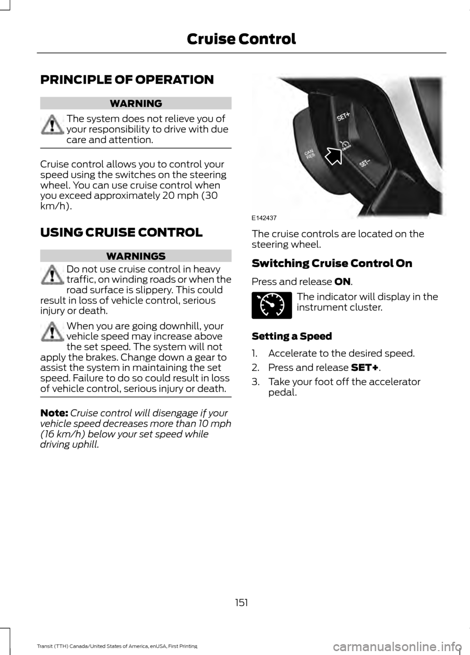
driving uphill. The cruise controls are located on the
steering wheel.
Switching Cruise Control On
Press and release ON.
The indicator will display in the
instrument cluster.
Setting a Speed
1. Accelerate to the desired speed.
2. Press and release
SET+.
3. Take your foot off the accelerator pedal.
151
Transit (TTH) Canada/United States of America, enUSA, First Printing Cruise ControlE142437 E71340
Page 175 of 411
The controller shows gain setting, output bar graph and the trailer connectivity
status in the information display as follows:
Action and Description
Message
Displays the current gain setting during a given ignition cycle
and when adjusting the gain setting. This also displays if you
use the manual control lever or make gain adjustments with
no trailer connected.
Trailer Brake
Gain:
No Trailer
Displays when you press your vehicle's brake pedal, or upon
use of the manual control lever. Bar indicators illuminate in
the information display to indicate the amount of power going
to the trailer brakes relative to the brake pedal or manual
control input. One bar indicates the least amount of output;
six bars indicate maximum output.
Trailer Brake
Gain:
Output:
Displays when the system senses a correct trailer wiring
connection during a given ignition cycle. For example a trailer
with electric trailer brakes.
Trailer Connected
Displays when the system senses a trailer connection and
then a disconnection, either intentional or unintentional,
during a given ignition cycle, this is accompanied by a single
audible tone. It also displays if a vehicle or trailer-wiring fault
occurs causing the trailer to appear disconnected. This
message can also display if you use the manual control lever
without a trailer connected.
Trailer Disconnected
Procedure for Adjusting the Gain Setting
The gain setting sets the trailer brake
controller for the specific towing condition.
You should change the setting as towing
conditions change. Changes to towing
conditions include trailer load, vehicle load,
road conditions and weather.
The gain should be set to provide the
maximum trailer braking assistance while
making sure the trailer wheels do not lock
when using the brakes. Locked trailer
wheels may lead to trailer instability.
Note: Only carry out this procedure in a
traffic-free environment at speeds of
approximately 20-25 mph (30-40 km/h). 1.
Make sure the trailer brakes are in good
working condition, functioning normally
and correctly adjusted. See a trailer
dealer if necessary.
2. Hook up the trailer and make the electrical connections according to the
trailer manufacturer's instructions.
3. Use the gain adjustment + and -
buttons to increase or decrease the
gain setting to the desired starting
point. A gain setting of six is a good
starting point for heavier loads.
4. In a traffic-free environment, tow the trailer on a dry, level surface at a speed
of 20-25 mph (30-40 km/h) and slide
the manual control lever completely.
172
Transit (TTH) Canada/United States of America, enUSA, First Printing Towing
Page 176 of 411
5. If the trailer wheels lock, indicated by
squealing tires, reduce the gain setting.
If the trailer wheels turn freely, increase
the gain setting. Repeat steps four and
five until the gain setting is at a point just below trailer wheel lock. If towing
a heavier trailer, trailer wheel lock may
not be attainable even with the
maximum gain setting of 10.
System Warning Messages Action and Description
Message
Displays in response to faults sensed by the trailer brake
controller, accompanied by a single tone. If this message
appears, contact an authorized dealer as soon as possible
for diagnosis and repair. The controller may still function, but
performance may be degraded.
Trailer Brake Module
Fault
Displays when there is a short circuit on the electric brake
output wire. If the message displays, accompanied by a single
tone, with no trailer connected, the problem is with your
vehicle wiring between the trailer brake controller and the 7-
pin connector. If the message only displays with a trailer
connected, the problem is with the trailer wiring. Consult a
trailer dealer for assistance. This can be a short to ground,
for example a chaffed wire, short to voltage, for example a
pulled pin on trailer emergency breakaway battery or the
trailer brakes may be drawing too much current.
Wiring Fault on Trailer
Note: An authorized dealer can diagnose the trailer brake controller to determine exactly
which trailer fault has occurred. However, the Ford Warranty does not cover this diagnosis
if the fault is with the trailer.
Points to Remember
• Do not attempt removal of the trailer
brake controller without consulting the
Workshop Manual. Damage to the unit
may result.
• Adjust gain setting before using the
trailer brake controller for the first time.
• Adjust gain setting, using the procedure
above, whenever road, weather and
trailer or vehicle loading conditions
change from when the gain was initially
set. •
Only use the manual control lever for
correct adjustment of the gain during
trailer setup. Misuse, such as
application during trailer sway, could
cause instability of trailer or tow
vehicle.
• Avoid towing in adverse weather
conditions. The trailer brake controller
does not provide anti-lock control of
the trailer wheels. Trailer wheels can
lock up on slippery surfaces, resulting
in instability of trailer or tow vehicle.
173
Transit (TTH) Canada/United States of America, enUSA, First Printing Towing
Page 178 of 411
•
If your vehicle is fitted with
AdvanceTrac with roll stability control
(RSC), this system may turn on during
typical cornering maneuvers with a
heavily loaded trailer. This is normal.
Turning the corner at a slower speed
while towing may reduce this tendency.
• If you are towing a trailer frequently in
hot weather, hilly conditions, at the
gross combined weight rating (or any
combination of these factors), consider
refilling your vehicle's rear axle with
synthetic gear lubricant (if the axle is
not already filled with it). See
Scheduled Maintenance (page 363).
• Allow more distance for stopping with
a trailer attached. Anticipate stops and
brake gradually.
• Avoid parking on a grade. However, if
you must park on a grade:
•Turn the steering wheel to point
your vehicle tires away from traffic
flow.
• Set your vehicle parking brake.
• Place the automatic transmission
in position park (P).
• Place wheel chocks in front of and
at the back of the trailer wheels.
(Trailer wheel chocks are not
included with your vehicle.)
Launching or Retrieving a Boat or
Personal Water Craft (PWC)
When backing down a ramp during boat
launching or retrieval:
• Do not allow the static water level to
rise above the bottom edge of the rear
bumper.
• Do not allow waves to break higher
than
6 in (15 cm) above the bottom
edge of the rear bumper.
Note: Disconnect the wiring to the trailer
before backing the trailer into the water. Note:
Reconnect the wiring to the trailer
after the trailer is removed from the water.
Exceeding these limits may allow water to
enter vehicle components:
• Causing internal damage to the
components.
• Affecting driveability, emissions, and
reliability.
Replace the rear axle lubricant anytime
the rear axle has been submerged in water.
Water may have contaminated the rear
axle lubricant, which is not normally
checked or changed unless a leak is
suspected or other axle repair is required.
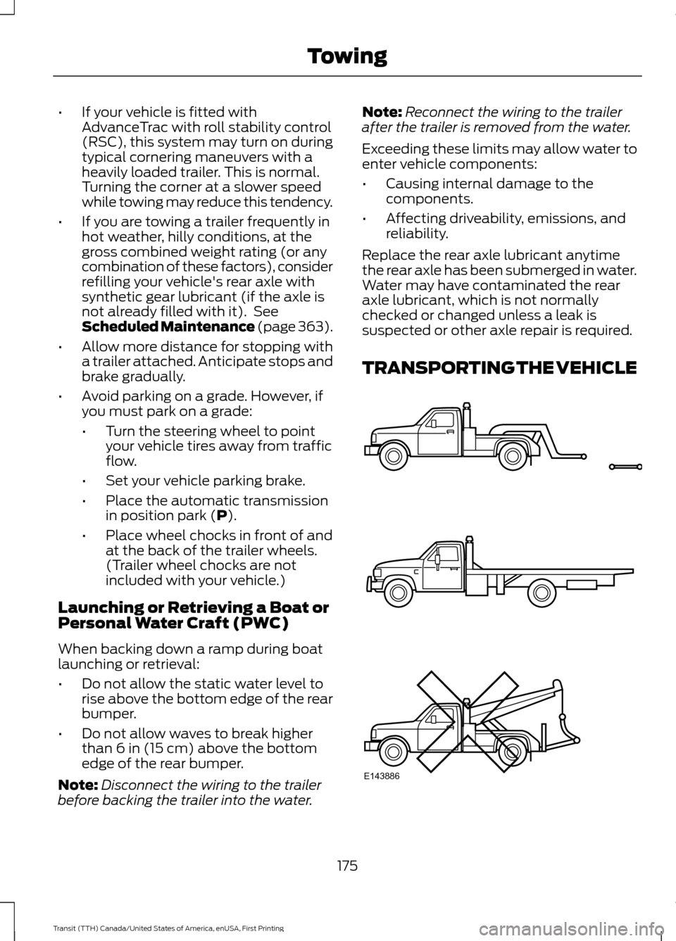
TRANSPORTING THE VEHICLE 175
Transit (TTH) Canada/United States of America, enUSA, First Printing TowingE143886
Page 249 of 411
15: Indicates the wheel or
rim diameter in inches. If
you change the wheel
size, you will have to
purchase new tires to
match the new wheel
diameter.
E
95:
Indicates the tire's
load index. It is an index
that relates to how much
weight a tire can carry.
You may find this
information in the Owner ’s
Guide. If not, contact a
local tire dealer.
F
H:
Indicates the tire's
speed rating. The speed
rating denotes the speed
at which a tire is designed
to be driven for extended
periods of time under a
G
standard condition of load
and inflation pressure.
The tires on your vehicle
may operate at different
conditions for load and
inflation pressure. These
speed ratings may need
to be adjusted for the
difference in conditions.
The ratings range from 81
mph (130 kph) to 186 mph
(299 kph). These ratings
are listed in the following
chart. United States of
America DOT Tire
Identification Number
(TIN):
This begins with
the letters DOT and
indicates that the tire
H
meets all federal
standards. The next two
numbers or letters are the
plant code designating
where it was
manufactured, the next
two are the tire size code
and the last four numbers
represent the week and
year the tire was built. For
example, the numbers 317
mean the 31st week of
1997. After 2000 the
numbers go to four digits.
For example, 2501 means
the 25th week of 2001.
The numbers in between
are identification codes
used for traceability. This
information is used to
contact customers if a tire
defect requires a recall.
M+S or M/S:
Mud and
Snow, AT: All Terrain, AS:
All Season.
I
Tire Ply Composition
and Material Used:
Indicates the number of
plies or the number of
layers of rubber-coated
fabric in the tire tread and
J
sidewall. Tire
246
Transit (TTH) Canada/United States of America, enUSA, First Printing Wheels and Tires