engine oil FORD WINDSTAR 2000 2.G Owners Manual
[x] Cancel search | Manufacturer: FORD, Model Year: 2000, Model line: WINDSTAR, Model: FORD WINDSTAR 2000 2.GPages: 280, PDF Size: 2.49 MB
Page 5 of 280
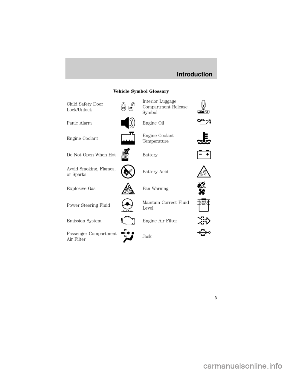
Vehicle Symbol Glossary
Child Safety Door
Lock/Unlock
Interior Luggage
Compartment Release
Symbol
Panic AlarmEngine Oil
Engine CoolantEngine Coolant
Temperature
Do Not Open When HotBattery
Avoid Smoking, Flames,
or SparksBattery Acid
Explosive GasFan Warning
Power Steering FluidMaintain Correct Fluid
LevelMAX
MIN
Emission SystemEngine Air Filter
Passenger Compartment
Air FilterJack
Introduction
5
Page 10 of 280
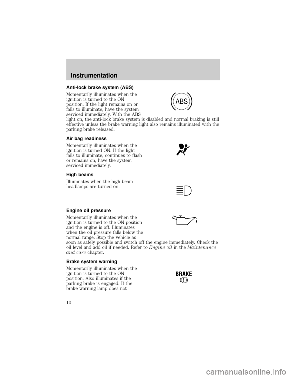
Anti-lock brake system (ABS)
Momentarily illuminates when the
ignition is turned to the ON
position. If the light remains on or
fails to illuminate, have the system
serviced immediately. With the ABS
light on, the anti-lock brake system is disabled and normal braking is still
effective unless the brake warning light also remains illuminated with the
parking brake released.
Air bag readiness
Momentarily illuminates when the
ignition is turned ON. If the light
fails to illuminate, continues to flash
or remains on, have the system
serviced immediately.
High beams
Illuminates when the high beam
headlamps are turned on.
Engine oil pressure
Momentarily illuminates when the
ignition is turned to the ON position
and the engine is off. Illuminates
when the oil pressure falls below the
normal range. Stop the vehicle as
soon as safely possible and switch off the engine immediately. Check the
oil level and add oil if needed. Refer toEngine oilin theMaintenance
and carechapter.
Brake system warning
Momentarily illuminates when the
ignition is turned to the ON
position. Also illuminates if the
parking brake is engaged. If the
brake warning lamp does not
ABS
!
BRAKE
Instrumentation
10
Page 19 of 280
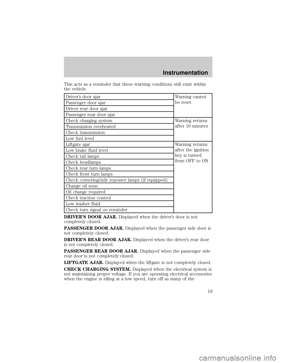
This acts as a reminder that these warning conditions still exist within
the vehicle.
Driver's door ajar Warning cannot
be reset
Passenger door ajar
Driver rear door ajar
Passenger rear door ajar
Check charging system Warning returns
after 10 minutes
Transmission overheated
Check transmission
Low fuel level
Liftgate ajar Warning returns
after the ignition
key is turned
from OFF to ON Low brake fluid level
Check tail lamps
Check headlamps
Check rear turn lamps
Check front turn lamps
Check cornering/side repeater lamps (if equipped)
Change oil soon
Oil change required
Check traction control
Low washer fluid
Check turn signal on reminder
DRIVER'S DOOR AJAR.Displayed when the driver's door is not
completely closed.
PASSENGER DOOR AJAR.Displayed when the passenger side door is
not completely closed.
DRIVER'S REAR DOOR AJAR.Displayed when the driver's rear door
is not completely closed.
PASSENGER REAR DOOR AJAR.Displayed when the passenger side
rear door is not completely closed.
LIFTGATE AJAR.Displayed when the liftgate is not completely closed.
CHECK CHARGING SYSTEM.Displayed when the electrical system is
not maintaining proper voltage. If you are operating electrical accessories
when the engine is idling at a low speed, turn off as many of the
Instrumentation
19
Page 21 of 280
LOW WASHER FLUID.Indicates the washer fluid reservoir is less than
one quarter full. Check the washer fluid level. Refer toWindshield
washer fluidin theMaintenance and carechapter.
CHECK TRACTION CONTROL (if equipped).Displayed when the
Traction Controlysystem is not operating properly. If this warning stays
on, contact your dealer for service as soon as possible. For further
information, refer toTraction controlyin theDrivingchapter.
CHANGE OIL SOON/OIL CHANGE REQUIRED.Displayed when the
engine oil life remaining is 5 percent or less. When oil life left is between
5% and 0%, the CHANGE OIL SOON message will be displayed. When oil
life left reaches 0%, the OIL CHANGE REQUIRED message will be
displayed.
An oil change is required whenever indicated by the message center.
USE ONLY RECOMMENDED ENGINE OILS.
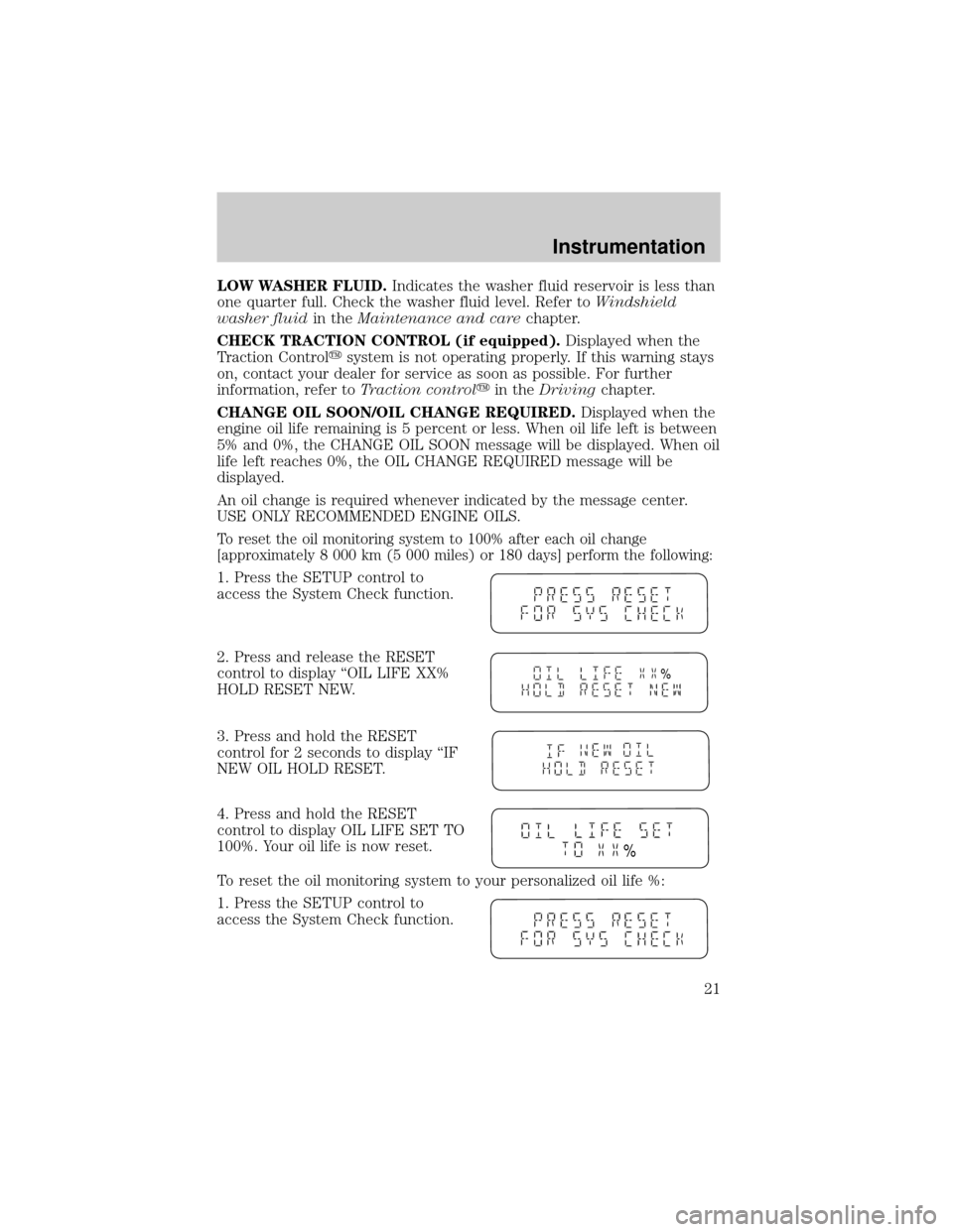
To reset the oil monitoring system to 100% after each oil change
[approximately 8 000 km (5 000 miles) or 180 days] perform the following:
1. Press the SETUP control to
access the System Check function.
2. Press and release the RESET
control to display ªOIL LIFE XX%
HOLD RESET NEW.
3. Press and hold the RESET
control for 2 seconds to display ªIF
NEW OIL HOLD RESET.
4. Press and hold the RESET
control to display OIL LIFE SET TO
100%. Your oil life is now reset.
To reset the oil monitoring system to your personalized oil life %:
1. Press the SETUP control to
access the System Check function.
%
%
Instrumentation
21
Page 187 of 280
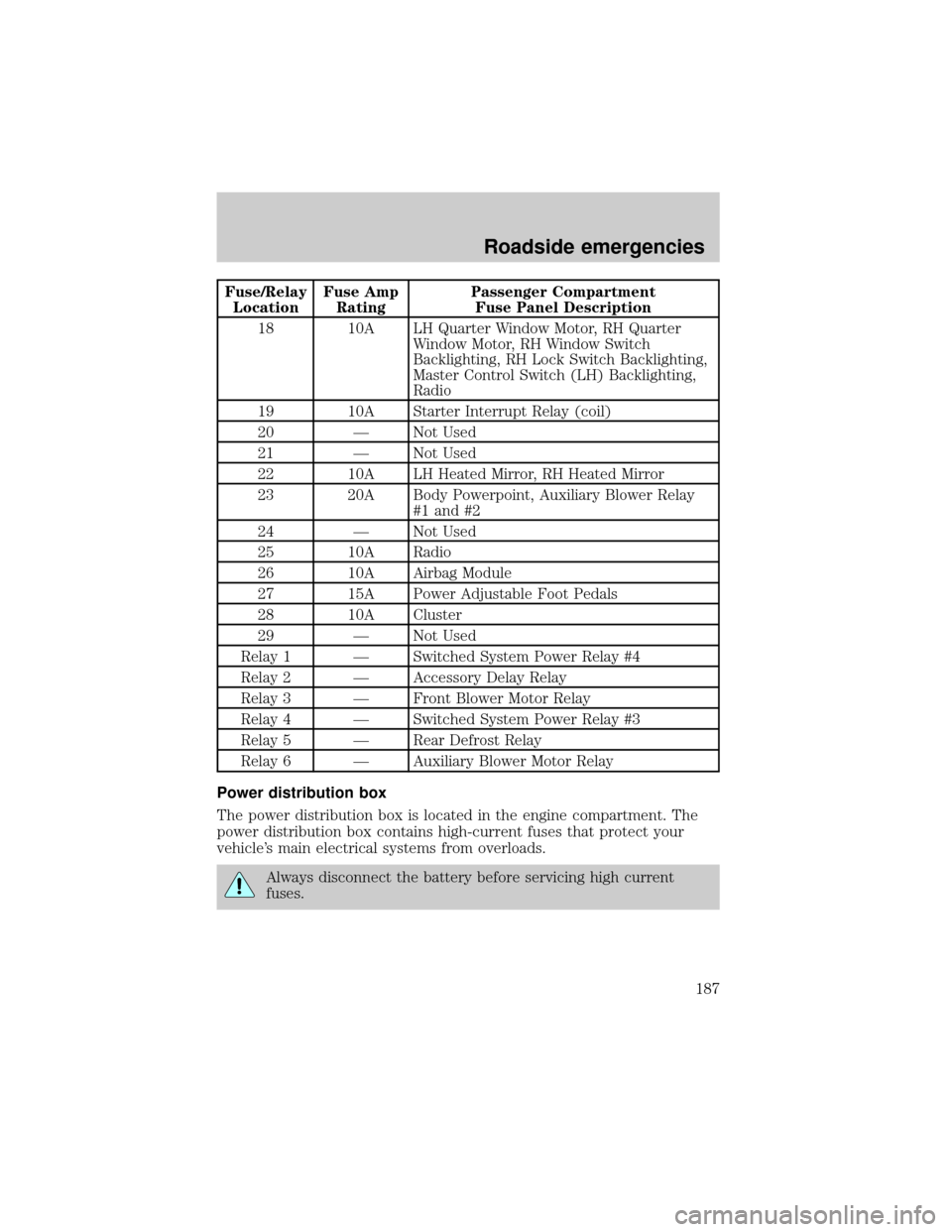
Fuse/Relay
LocationFuse Amp
RatingPassenger Compartment
Fuse Panel Description
18 10A LH Quarter Window Motor, RH Quarter
Window Motor, RH Window Switch
Backlighting, RH Lock Switch Backlighting,
Master Control Switch (LH) Backlighting,
Radio
19 10A Starter Interrupt Relay (coil)
20 Ð Not Used
21 Ð Not Used
22 10A LH Heated Mirror, RH Heated Mirror
23 20A Body Powerpoint, Auxiliary Blower Relay
#1 and #2
24 Ð Not Used
25 10A Radio
26 10A Airbag Module
27 15A Power Adjustable Foot Pedals
28 10A Cluster
29 Ð Not Used
Relay 1 Ð Switched System Power Relay #4
Relay 2 Ð Accessory Delay Relay
Relay 3 Ð Front Blower Motor Relay
Relay 4 Ð Switched System Power Relay #3
Relay 5 Ð Rear Defrost Relay
Relay 6 Ð Auxiliary Blower Motor Relay
Power distribution box
The power distribution box is located in the engine compartment. The
power distribution box contains high-current fuses that protect your
vehicle's main electrical systems from overloads.
Always disconnect the battery before servicing high current
fuses.
Roadside emergencies
187
Page 189 of 280
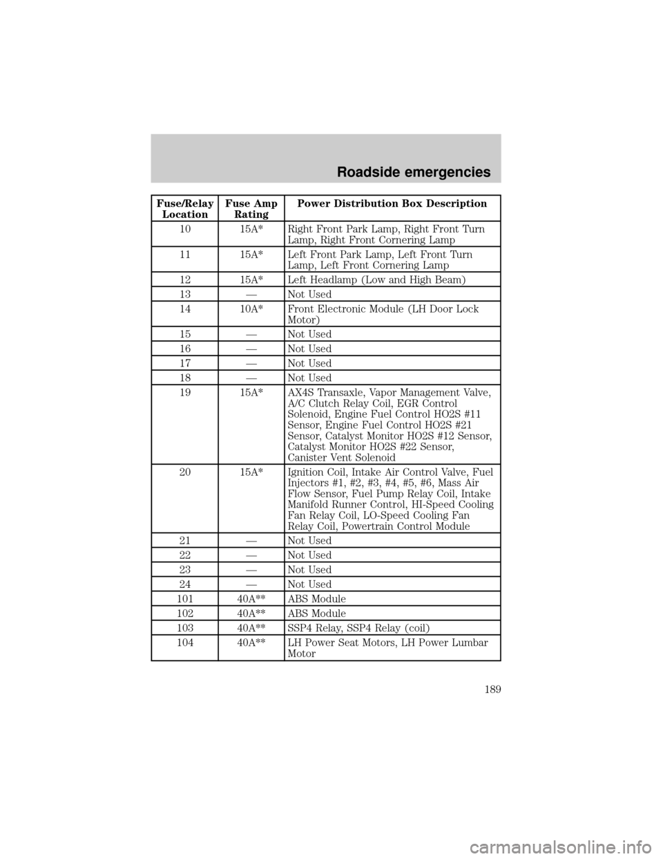
Fuse/Relay
LocationFuse Amp
RatingPower Distribution Box Description
10 15A* Right Front Park Lamp, Right Front Turn
Lamp, Right Front Cornering Lamp
11 15A* Left Front Park Lamp, Left Front Turn
Lamp, Left Front Cornering Lamp
12 15A* Left Headlamp (Low and High Beam)
13 Ð Not Used
14 10A* Front Electronic Module (LH Door Lock
Motor)
15 Ð Not Used
16 Ð Not Used
17 Ð Not Used
18 Ð Not Used
19 15A* AX4S Transaxle, Vapor Management Valve,
A/C Clutch Relay Coil, EGR Control
Solenoid, Engine Fuel Control HO2S #11
Sensor, Engine Fuel Control HO2S #21
Sensor, Catalyst Monitor HO2S #12 Sensor,
Catalyst Monitor HO2S #22 Sensor,
Canister Vent Solenoid
20 15A* Ignition Coil, Intake Air Control Valve, Fuel
Injectors #1, #2, #3, #4, #5, #6, Mass Air
Flow Sensor, Fuel Pump Relay Coil, Intake
Manifold Runner Control, HI-Speed Cooling
Fan Relay Coil, LO-Speed Cooling Fan
Relay Coil, Powertrain Control Module
21 Ð Not Used
22 Ð Not Used
23 Ð Not Used
24 Ð Not Used
101 40A** ABS Module
102 40A** ABS Module
103 40A** SSP4 Relay, SSP4 Relay (coil)
104 40A** LH Power Seat Motors, LH Power Lumbar
Motor
Roadside emergencies
189
Page 190 of 280
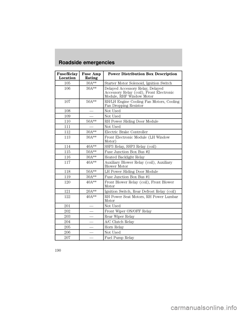
Fuse/Relay
LocationFuse Amp
RatingPower Distribution Box Description
105 30A** Starter Motor Solenoid, Ignition Switch
106 30A** Delayed Accessory Relay, Delayed
Accessory Relay (coil), Front Electronic
Module, RHF Window Motor
107 50A** RH/LH Engine Cooling Fan Motors, Cooling
Fan Dropping Resistor
108 Ð Not Used
109 Ð Not Used
110 50A** RH Power Sliding Door Module
111 Ð Not Used
112 30A** Electric Brake Controller
113 30A** Front Electronic Module (LH Window
Motor)
114 40A** SSP3 Relay, SSP3 Relay (coil)
115 50A** Fuse Junction Box Bus #2
116 30A** Heated Backlight Relay
117 40A** Auxiliary Blower Relay (coil), Auxiliary
Blower Motor
118 50A** LH Power Sliding Door Module
119 30A** Fuse Junction Box Bus #1
120 40A** Front Blower Relay (coil), Front Blower
Motor
121 20A** Ignition Switch, Rear Defrost Relay (coil)
122 40A** RH Power Seat Motors, RH Power Lumbar
Motor
201 Ð Not Used
202 Ð Front Wiper ON/OFF Relay
203 Ð Rear Wiper Relay
204 Ð A/C Clutch Relay
205 Ð Horn Relay
206 Ð Not Used
207 Ð Fuel Pump Relay
Roadside emergencies
190
Page 205 of 280
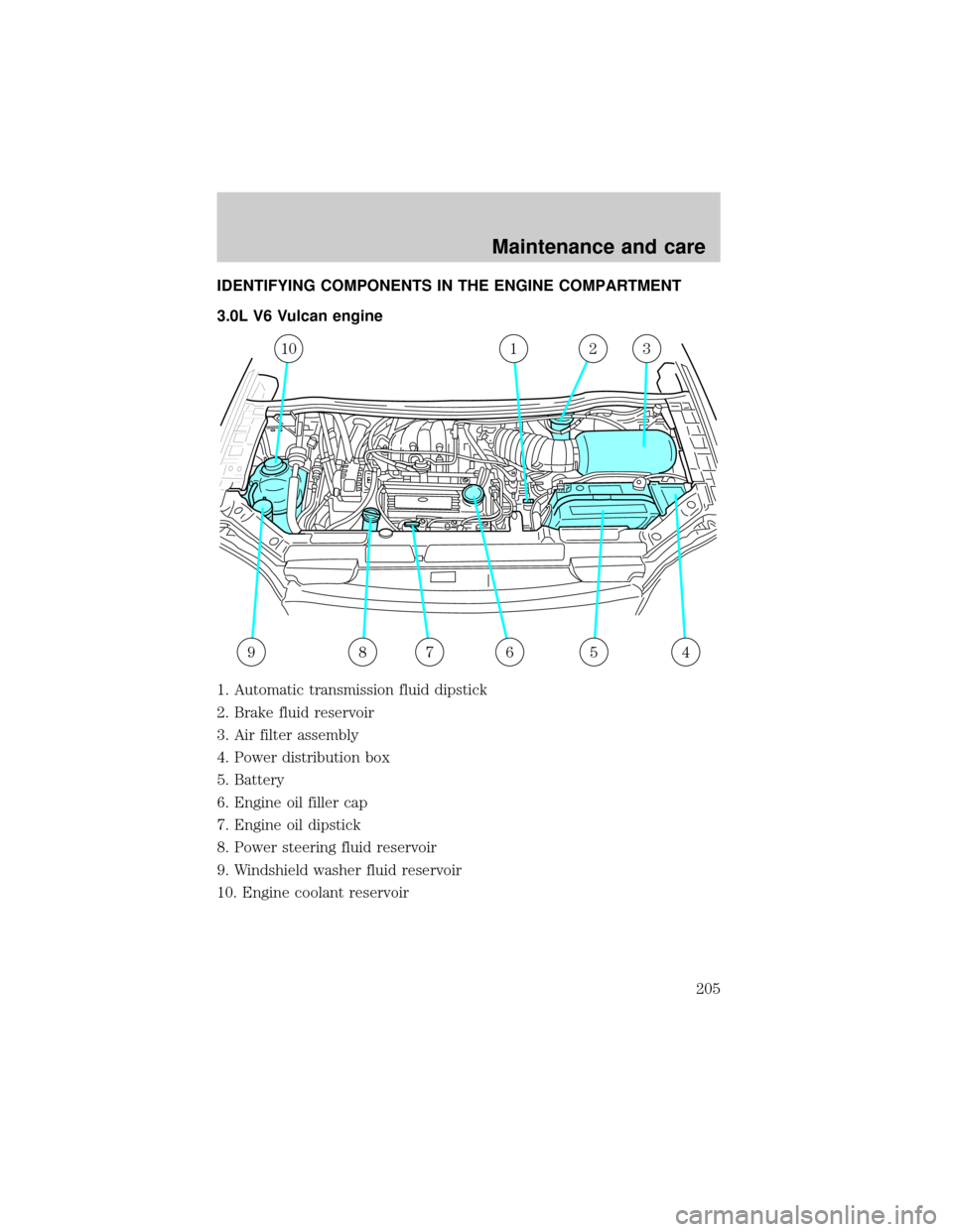
IDENTIFYING COMPONENTS IN THE ENGINE COMPARTMENT
3.0L V6 Vulcan engine
1. Automatic transmission fluid dipstick
2. Brake fluid reservoir
3. Air filter assembly
4. Power distribution box
5. Battery
6. Engine oil filler cap
7. Engine oil dipstick
8. Power steering fluid reservoir
9. Windshield washer fluid reservoir
10. Engine coolant reservoir
987654
10123
Maintenance and care
205
Page 206 of 280
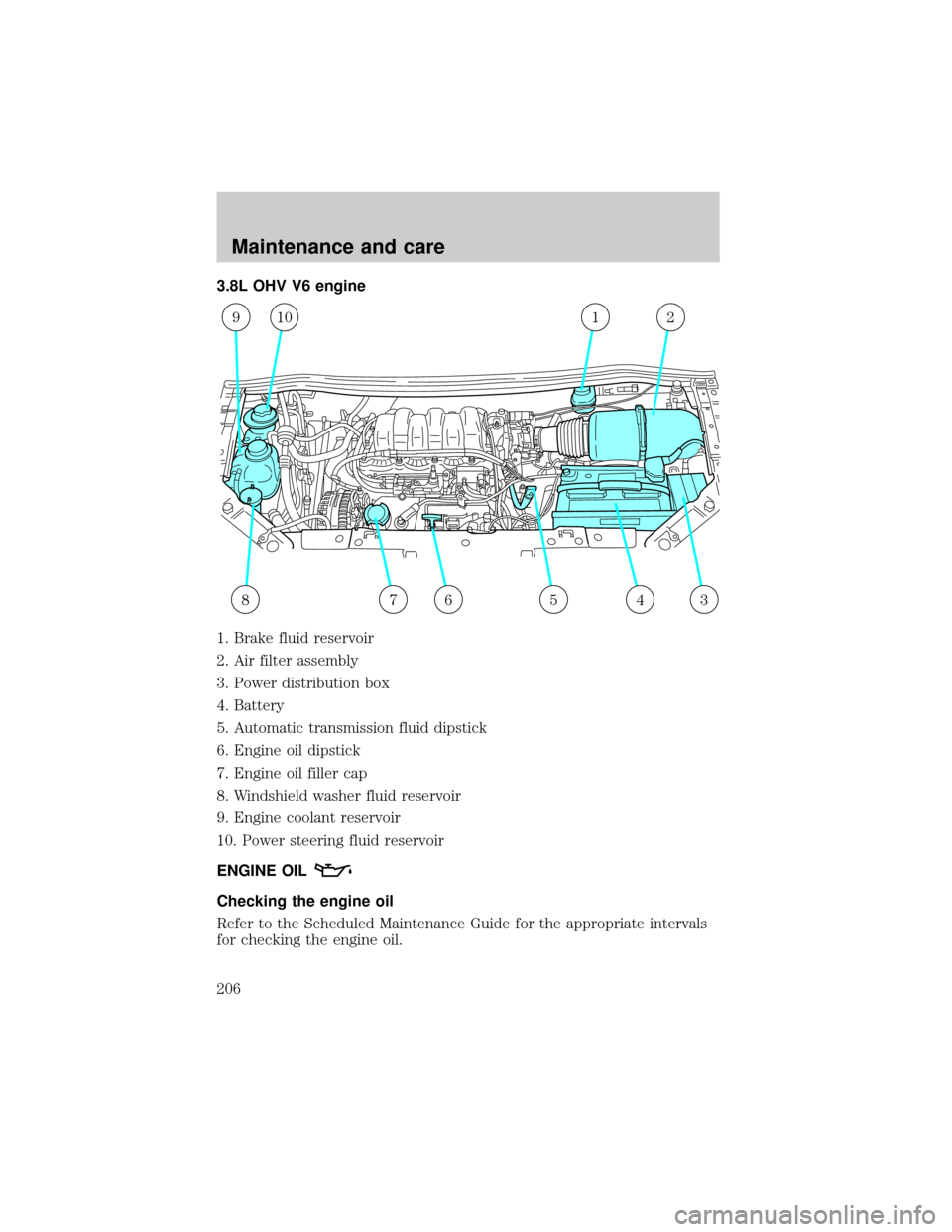
3.8L OHV V6 engine
1. Brake fluid reservoir
2. Air filter assembly
3. Power distribution box
4. Battery
5. Automatic transmission fluid dipstick
6. Engine oil dipstick
7. Engine oil filler cap
8. Windshield washer fluid reservoir
9. Engine coolant reservoir
10. Power steering fluid reservoir
ENGINE OIL
Checking the engine oil
Refer to the Scheduled Maintenance Guide for the appropriate intervals
for checking the engine oil.
345678
91012
Maintenance and care
206
Page 207 of 280
1. Make sure the vehicle is on level ground.
2. Turn the engine off and wait a few minutes for the oil to drain into the
oil pan.
3. Set the parking brake and ensure the gearshift is securely latched in P
(Park).
4. Open the hood. Protect yourself from engine heat.
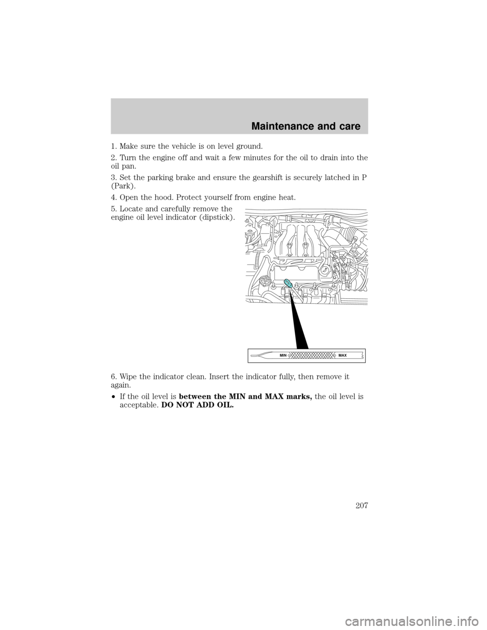
5. Locate and carefully remove the
engine oil level indicator (dipstick).
6. Wipe the indicator clean. Insert the indicator fully, then remove it
again.
²If the oil level isbetween the MIN and MAX marks,the oil level is
acceptable.DO NOT ADD OIL.
MAX MIN
Maintenance and care
207