sensor FORD WINDSTAR 2001 2.G User Guide
[x] Cancel search | Manufacturer: FORD, Model Year: 2001, Model line: WINDSTAR, Model: FORD WINDSTAR 2001 2.GPages: 288, PDF Size: 2.6 MB
Page 148 of 288
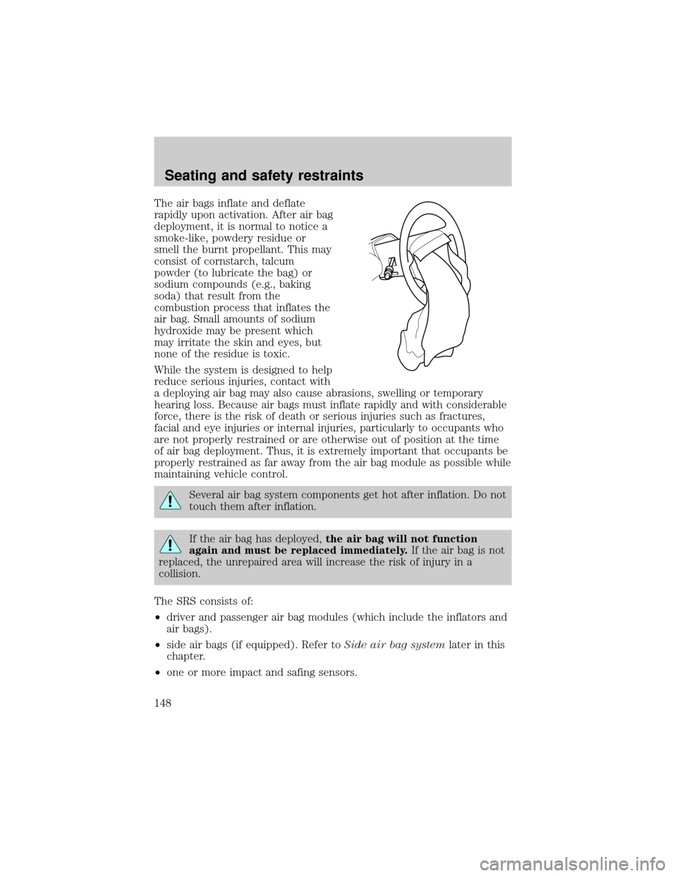
The air bags inflate and deflate
rapidly upon activation. After air bag
deployment, it is normal to notice a
smoke-like, powdery residue or
smell the burnt propellant. This may
consist of cornstarch, talcum
powder (to lubricate the bag) or
sodium compounds (e.g., baking
soda) that result from the
combustion process that inflates the
air bag. Small amounts of sodium
hydroxide may be present which
may irritate the skin and eyes, but
none of the residue is toxic.
While the system is designed to help
reduce serious injuries, contact with
a deploying air bag may also cause abrasions, swelling or temporary
hearing loss. Because air bags must inflate rapidly and with considerable
force, there is the risk of death or serious injuries such as fractures,
facial and eye injuries or internal injuries, particularly to occupants who
are not properly restrained or are otherwise out of position at the time
of air bag deployment. Thus, it is extremely important that occupants be
properly restrained as far away from the air bag module as possible while
maintaining vehicle control.
Several air bag system components get hot after inflation. Do not
touch them after inflation.
If the air bag has deployed,the air bag will not function
again and must be replaced immediately.If the air bag is not
replaced, the unrepaired area will increase the risk of injury in a
collision.
The SRS consists of:
²driver and passenger air bag modules (which include the inflators and
air bags).
²side air bags (if equipped). Refer toSide air bag systemlater in this
chapter.
²one or more impact and safing sensors.
Seating and safety restraints
148
Page 149 of 288
²a readiness light and tone.
²diagnostic module.
²and the electrical wiring which connects the components.
The diagnostic module monitors its own internal circuits and the
supplemental air bag electrical system warning (including the impact
sensors), the system wiring, the air bag system readiness light, the air
bag back up power and the air bag ignitors.
Side air bag system (if equipped)
Do not place objects or mount equipment on or near the air bag
cover on the side of the seatbacks of the front seats or in front
seat areas that may come into contact with a deploying air bag. Failure
to follow these instructions may increase the risk of personal injury in
the event of a collision.
Do not use accessory seat covers. The use of accessory seat
covers may prevent the deployment of the side air bags and
increase the risk of injury in an accident.
Do not lean your head on the door. The side air bag could injure
you as it deploys from the side of the seatback.
Do not attempt to service, repair, or modify the air bag
Supplemental Restraint System, its fuses or the seat cover on a
seat containing an air bag. See your Ford or Lincoln Mercury dealer.
All occupants of the vehicle including the driver should always
wear their safety belts even when an air bag SRS is provided.
Seating and safety restraints
149
Page 150 of 288
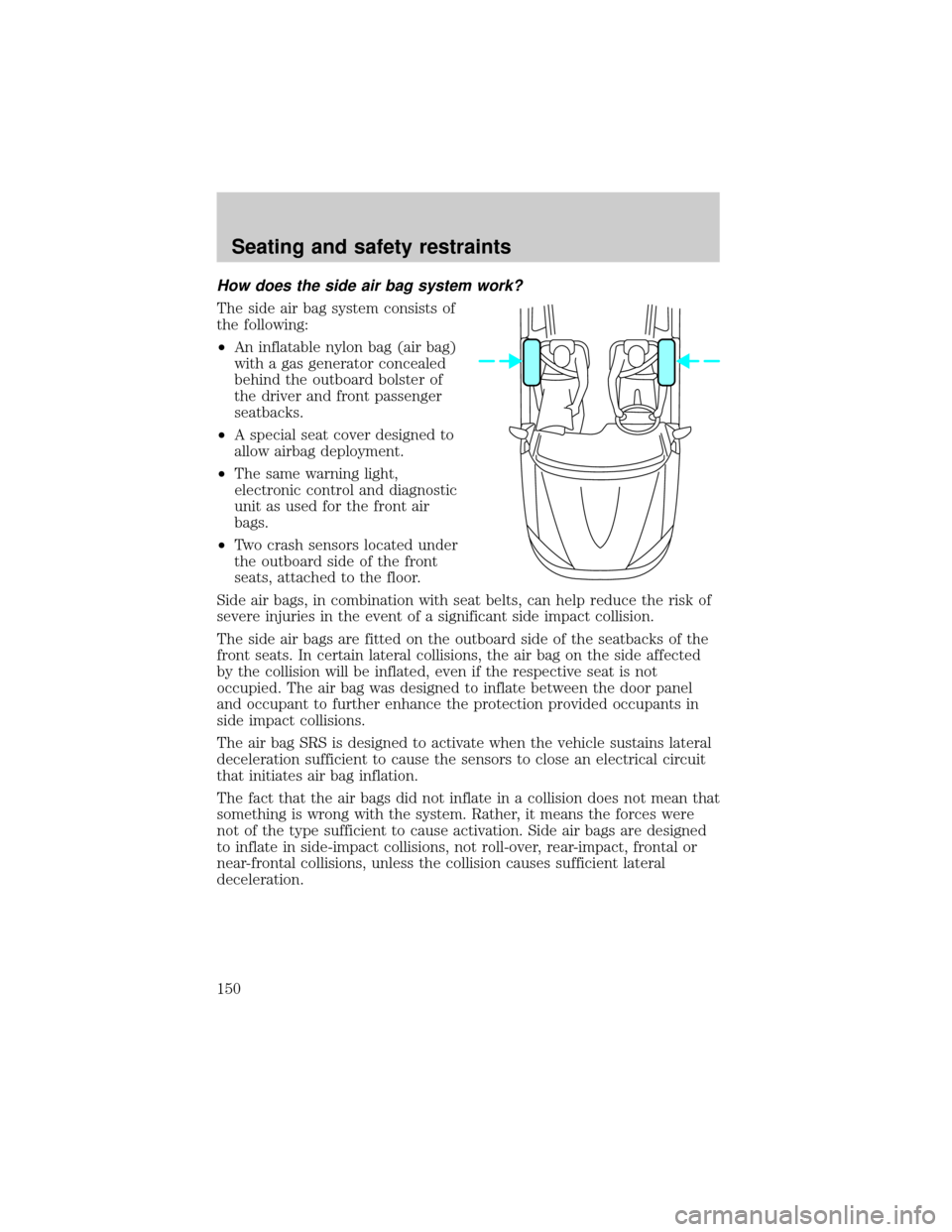
How does the side air bag system work?
The side air bag system consists of
the following:
²An inflatable nylon bag (air bag)
with a gas generator concealed
behind the outboard bolster of
the driver and front passenger
seatbacks.
²A special seat cover designed to
allow airbag deployment.
²The same warning light,
electronic control and diagnostic
unit as used for the front air
bags.
²Two crash sensors located under
the outboard side of the front
seats, attached to the floor.
Side air bags, in combination with seat belts, can help reduce the risk of
severe injuries in the event of a significant side impact collision.
The side air bags are fitted on the outboard side of the seatbacks of the
front seats. In certain lateral collisions, the air bag on the side affected
by the collision will be inflated, even if the respective seat is not
occupied. The air bag was designed to inflate between the door panel
and occupant to further enhance the protection provided occupants in
side impact collisions.
The air bag SRS is designed to activate when the vehicle sustains lateral
deceleration sufficient to cause the sensors to close an electrical circuit
that initiates air bag inflation.
The fact that the air bags did not inflate in a collision does not mean that
something is wrong with the system. Rather, it means the forces were
not of the type sufficient to cause activation. Side air bags are designed
to inflate in side-impact collisions, not roll-over, rear-impact, frontal or
near-frontal collisions, unless the collision causes sufficient lateral
deceleration.
Seating and safety restraints
150
Page 169 of 288
The BRAKE warning lamp in the
instrument cluster illuminates and
remains illuminated (when the
ignition is turned ON) until the
parking brake is released.
The parking brake is not recommended to stop a moving vehicle.
However, if the normal brakes fail, the parking brake can be used to stop
your vehicle in an emergency. Since the parking brake applies only the
rear brakes, the vehicle's stopping distance will increase greatly and the
handling of your vehicle will be adversely affected.
Always set the parking brake fully and make sure that the
gearshift is securely latched in P (Park) (automatic transaxle).
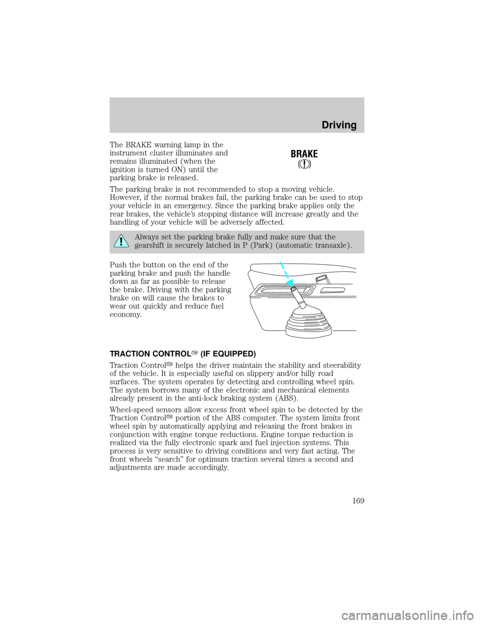
Push the button on the end of the
parking brake and push the handle
down as far as possible to release
the brake. Driving with the parking
brake on will cause the brakes to
wear out quickly and reduce fuel
economy.
TRACTION CONTROLY(IF EQUIPPED)
Traction Controlyhelps the driver maintain the stability and steerability
of the vehicle. It is especially useful on slippery and/or hilly road
surfaces. The system operates by detecting and controlling wheel spin.
The system borrows many of the electronic and mechanical elements
already present in the anti-lock braking system (ABS).
Wheel-speed sensors allow excess front wheel spin to be detected by the
Traction Controlyportion of the ABS computer. The system limits front
wheel spin by automatically applying and releasing the front brakes in
conjunction with engine torque reductions. Engine torque reduction is
realized via the fully electronic spark and fuel injection systems. This
process is very sensitive to driving conditions and very fast acting. The
front wheels ªsearchº for optimum traction several times a second and
adjustments are made accordingly.
!
BRAKE
Driving
169
Page 170 of 288
The Traction Controlysystem will assist you in making better use of
available traction on slippery surfaces. The system is a driver aid which
makes your vehicle easier to handle primarily on snow and ice covered
roads.
During Traction Controlyoperation, TRACTION CONTROL OK is
displayed on the message center (if equipped). You may hear an electric
motor type of sound coming from the engine compartment and the
engine will not ªrev-upº when you push further on the accelerator. This
is normal system behavior.
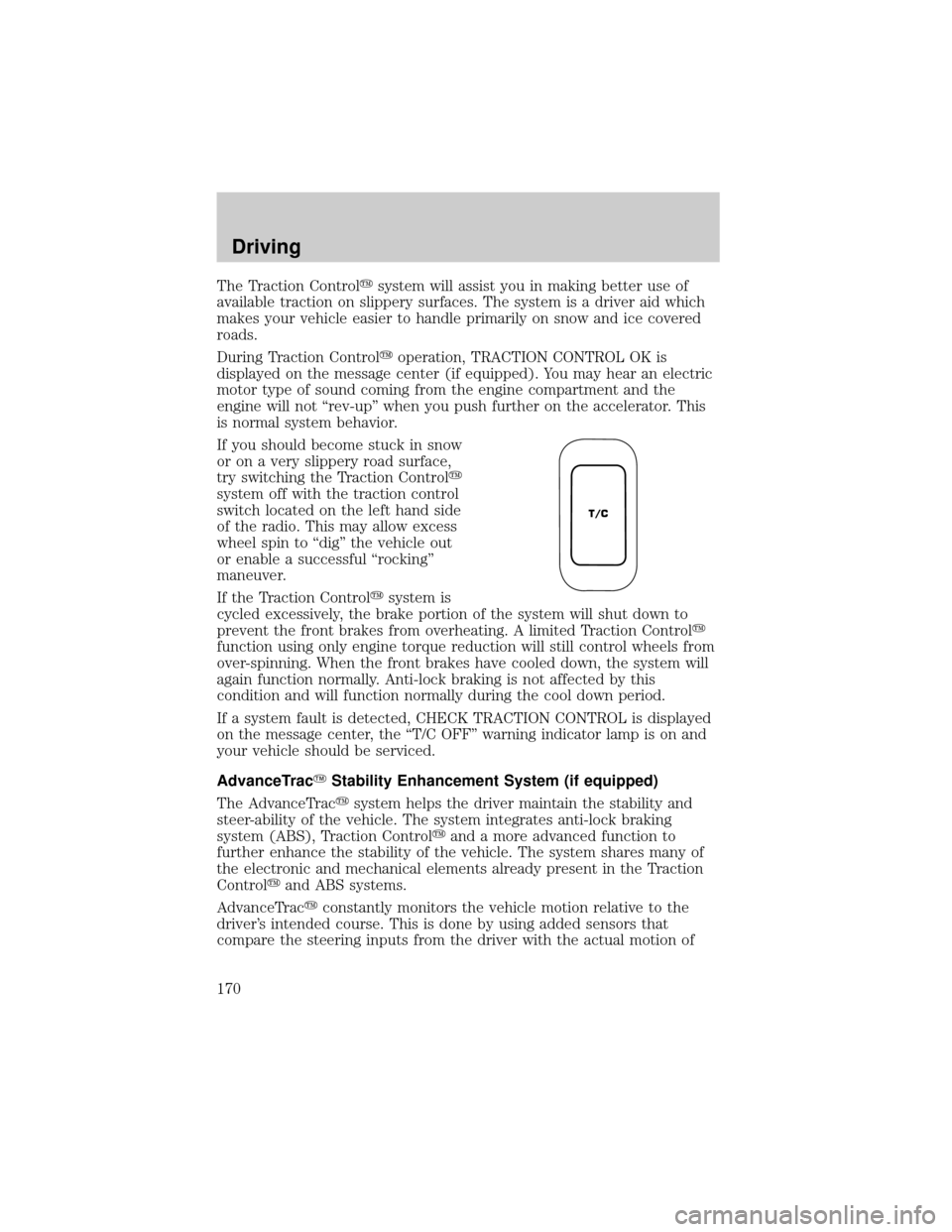
If you should become stuck in snow
or on a very slippery road surface,
try switching the Traction Controly
system off with the traction control
switch located on the left hand side
of the radio. This may allow excess
wheel spin to ªdigº the vehicle out
or enable a successful ªrockingº
maneuver.
If the Traction Controlysystem is
cycled excessively, the brake portion of the system will shut down to
prevent the front brakes from overheating. A limited Traction Controly
function using only engine torque reduction will still control wheels from
over-spinning. When the front brakes have cooled down, the system will
again function normally. Anti-lock braking is not affected by this
condition and will function normally during the cool down period.
If a system fault is detected, CHECK TRACTION CONTROL is displayed
on the message center, the ªT/C OFFº warning indicator lamp is on and
your vehicle should be serviced.
AdvanceTracYStability Enhancement System (if equipped)
The AdvanceTracysystem helps the driver maintain the stability and
steer-ability of the vehicle. The system integrates anti-lock braking
system (ABS), Traction Controlyand a more advanced function to
further enhance the stability of the vehicle. The system shares many of
the electronic and mechanical elements already present in the Traction
Controlyand ABS systems.
AdvanceTracyconstantly monitors the vehicle motion relative to the
driver's intended course. This is done by using added sensors that
compare the steering inputs from the driver with the actual motion of
T/C
Driving
170
Page 172 of 288
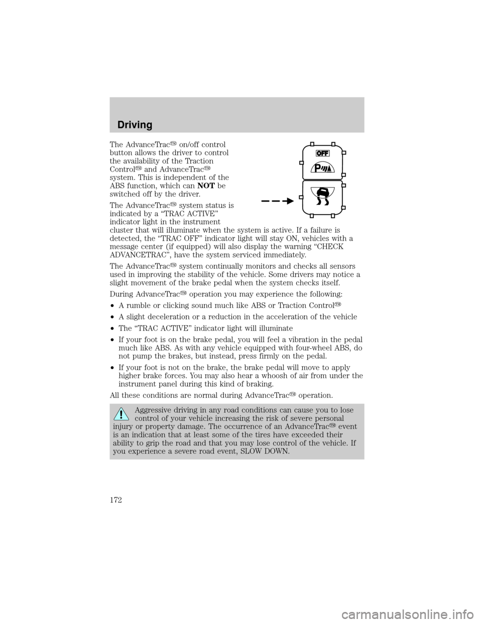
The AdvanceTracyon/off control
button allows the driver to control
the availability of the Traction
Controlyand AdvanceTracy
system. This is independent of the
ABS function, which canNOTbe
switched off by the driver.
The AdvanceTracysystem status is
indicated by a ªTRAC ACTIVEº
indicator light in the instrument
cluster that will illuminate when the system is active. If a failure is
detected, the ªTRAC OFFº indicator light will stay ON, vehicles with a
message center (if equipped) will also display the warning ªCHECK
ADVANCETRACº, have the system serviced immediately.
The AdvanceTracysystem continually monitors and checks all sensors
used in improving the stability of the vehicle. Some drivers may notice a
slight movement of the brake pedal when the system checks itself.
During AdvanceTracyoperation you may experience the following:
²A rumble or clicking sound much like ABS or Traction Controly
²A slight deceleration or a reduction in the acceleration of the vehicle
²The ªTRAC ACTIVEº indicator light will illuminate
²If your foot is on the brake pedal, you will feel a vibration in the pedal
much like ABS. As with any vehicle equipped with four-wheel ABS, do
not pump the brakes, but instead, press firmly on the pedal.
²If your foot is not on the brake, the brake pedal will move to apply
higher brake forces. You may also hear a whoosh of air from under the
instrument panel during this kind of braking.
All these conditions are normal during AdvanceTracyoperation.
Aggressive driving in any road conditions can cause you to lose
control of your vehicle increasing the risk of severe personal
injury or property damage. The occurrence of an AdvanceTracyevent
is an indication that at least some of the tires have exceeded their
ability to grip the road and that you may lose control of the vehicle. If
you experience a severe road event, SLOW DOWN.
Driving
172
Page 191 of 288
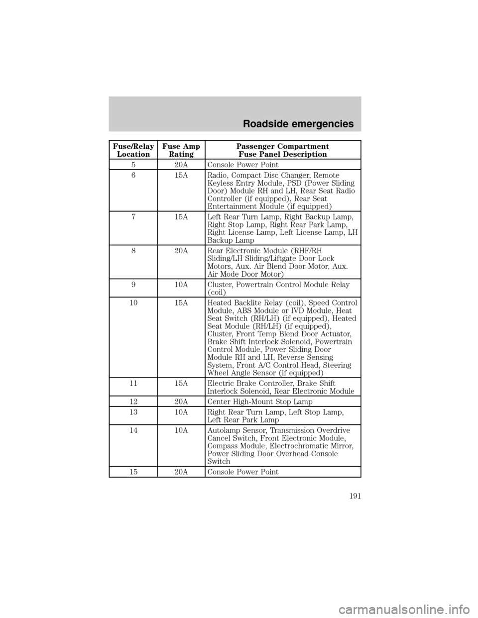
Fuse/Relay
LocationFuse Amp
RatingPassenger Compartment
Fuse Panel Description
5 20A Console Power Point
6 15A Radio, Compact Disc Changer, Remote
Keyless Entry Module, PSD (Power Sliding
Door) Module RH and LH, Rear Seat Radio
Controller (if equipped), Rear Seat
Entertainment Module (if equipped)
7 15A Left Rear Turn Lamp, Right Backup Lamp,
Right Stop Lamp, Right Rear Park Lamp,
Right License Lamp, Left License Lamp, LH
Backup Lamp
8 20A Rear Electronic Module (RHF/RH
Sliding/LH Sliding/Liftgate Door Lock
Motors, Aux. Air Blend Door Motor, Aux.
Air Mode Door Motor)
9 10A Cluster, Powertrain Control Module Relay
(coil)
10 15A Heated Backlite Relay (coil), Speed Control
Module, ABS Module or IVD Module, Heat
Seat Switch (RH/LH) (if equipped), Heated
Seat Module (RH/LH) (if equipped),
Cluster, Front Temp Blend Door Actuator,
Brake Shift Interlock Solenoid, Powertrain
Control Module, Power Sliding Door
Module RH and LH, Reverse Sensing
System, Front A/C Control Head, Steering
Wheel Angle Sensor (if equipped)
11 15A Electric Brake Controller, Brake Shift
Interlock Solenoid, Rear Electronic Module
12 20A Center High-Mount Stop Lamp
13 10A Right Rear Turn Lamp, Left Stop Lamp,
Left Rear Park Lamp
14 10A Autolamp Sensor, Transmission Overdrive
Cancel Switch, Front Electronic Module,
Compass Module, Electrochromatic Mirror,
Power Sliding Door Overhead Console
Switch
15 20A Console Power Point
Roadside emergencies
191
Page 192 of 288
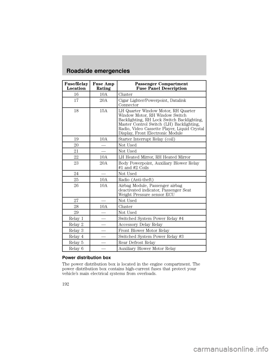
Fuse/Relay
LocationFuse Amp
RatingPassenger Compartment
Fuse Panel Description
16 10A Cluster
17 20A Cigar Lighter/Powerpoint, Datalink
Connector
18 15A LH Quarter Window Motor, RH Quarter
Window Motor, RH Window Switch
Backlighting, RH Lock Switch Backlighting,
Master Control Switch (LH) Backlighting,
Radio, Video Cassette Player, Liquid Crystal
Display, Front Electronic Module
19 10A Starter Interrupt Relay (coil)
20 Ð Not Used
21 Ð Not Used
22 10A LH Heated Mirror, RH Heated Mirror
23 20A Body Powerpoint, Auxiliary Blower Relay
#1 and #2 Coils
24 Ð Not Used
25 10A Radio (Anti-theft)
26 10A Airbag Module, Passenger airbag
deactivated indicator, Passenger Seat
Weight Pressure sensor ECU
27 Ð Not Used
28 10A Cluster
29 Ð Not Used
Relay 1 Ð Switched System Power Relay #4
Relay 2 Ð Accessory Delay Relay
Relay 3 Ð Front Blower Motor Relay
Relay 4 Ð Switched System Power Relay #3
Relay 5 Ð Rear Defrost Relay
Relay 6 Ð Auxiliary Blower Motor Relay
Power distribution box
The power distribution box is located in the engine compartment. The
power distribution box contains high-current fuses that protect your
vehicle's main electrical systems from overloads.
Roadside emergencies
192
Page 194 of 288
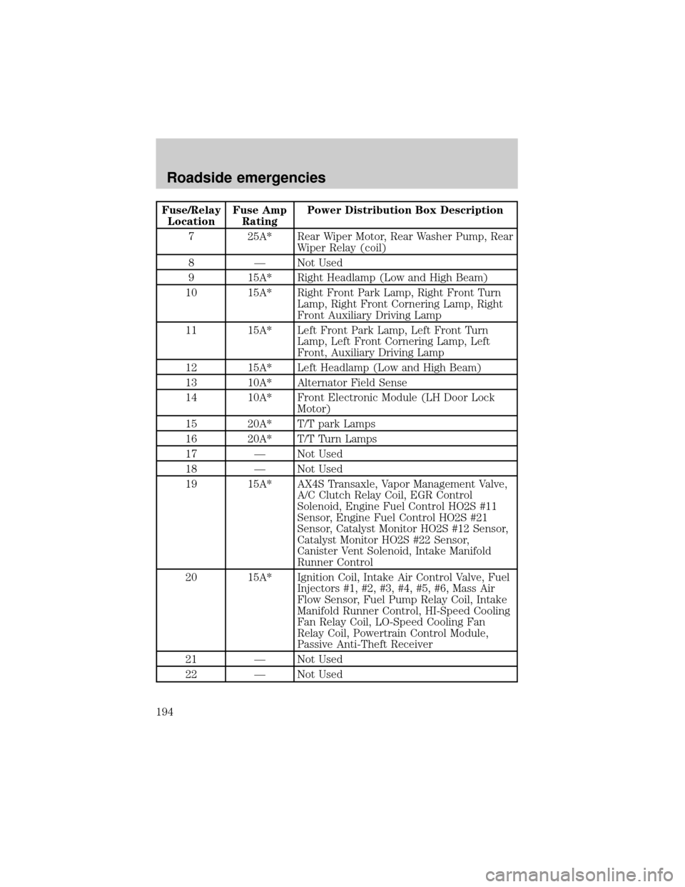
Fuse/Relay
LocationFuse Amp
RatingPower Distribution Box Description
7 25A* Rear Wiper Motor, Rear Washer Pump, Rear
Wiper Relay (coil)
8 Ð Not Used
9 15A* Right Headlamp (Low and High Beam)
10 15A* Right Front Park Lamp, Right Front Turn
Lamp, Right Front Cornering Lamp, Right
Front Auxiliary Driving Lamp
11 15A* Left Front Park Lamp, Left Front Turn
Lamp, Left Front Cornering Lamp, Left
Front, Auxiliary Driving Lamp
12 15A* Left Headlamp (Low and High Beam)
13 10A* Alternator Field Sense
14 10A* Front Electronic Module (LH Door Lock
Motor)
15 20A* T/T park Lamps
16 20A* T/T Turn Lamps
17 Ð Not Used
18 Ð Not Used
19 15A* AX4S Transaxle, Vapor Management Valve,
A/C Clutch Relay Coil, EGR Control
Solenoid, Engine Fuel Control HO2S #11
Sensor, Engine Fuel Control HO2S #21
Sensor, Catalyst Monitor HO2S #12 Sensor,
Catalyst Monitor HO2S #22 Sensor,
Canister Vent Solenoid, Intake Manifold
Runner Control
20 15A* Ignition Coil, Intake Air Control Valve, Fuel
Injectors #1, #2, #3, #4, #5, #6, Mass Air
Flow Sensor, Fuel Pump Relay Coil, Intake
Manifold Runner Control, HI-Speed Cooling
Fan Relay Coil, LO-Speed Cooling Fan
Relay Coil, Powertrain Control Module,
Passive Anti-Theft Receiver
21 Ð Not Used
22 Ð Not Used
Roadside emergencies
194
Page 232 of 288
which all passenger car tires must meet under the Federal Motor Vehicle
Safety Standard No. 109. Grades B and A represent higher levels of
performance on the laboratory test wheel than the minimum required by
law.
The temperature grade for this tire is established for a tire that
is properly inflated and not overloaded. Excessive speed,
underinflation, or excessive loading, either separately or in
combination, can cause heat buildup and possible tire failure.
SERVICING YOUR TIRES
Low tire warning (if equipped)
The low tire warning system is designed to detect a significant loss of
inflation inany one of your tireson your vehicle. The system uses the
Anti-lock brake wheel speed sensors to detect a change in wheel speed
due to tire deflation.
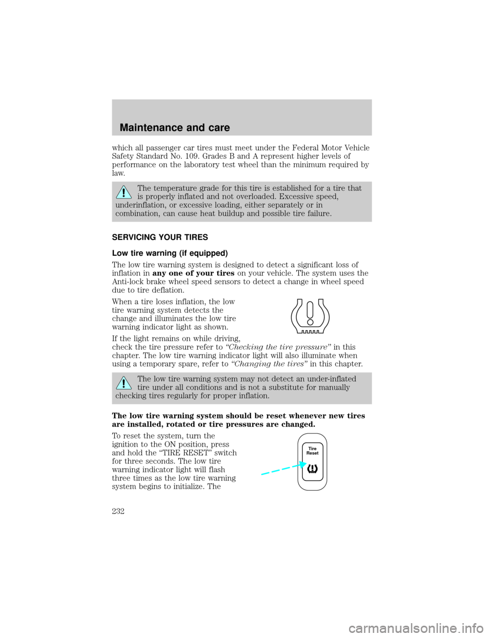
When a tire loses inflation, the low
tire warning system detects the
change and illuminates the low tire
warning indicator light as shown.
If the light remains on while driving,
check the tire pressure refer toªChecking the tire pressureºin this
chapter. The low tire warning indicator light will also illuminate when
using a temporary spare, refer toªChanging the tiresºin this chapter.
The low tire warning system may not detect an under-inflated
tire under all conditions and is not a substitute for manually
checking tires regularly for proper inflation.
The low tire warning system should be reset whenever new tires
are installed, rotated or tire pressures are changed.
To reset the system, turn the
ignition to the ON position, press
and hold the ªTIRE RESETº switch
for three seconds. The low tire
warning indicator light will flash
three times as the low tire warning
system begins to initialize. The
Tire
Reset
Maintenance and care
232