tires FORD WINDSTAR 2001 2.G Owners Manual
[x] Cancel search | Manufacturer: FORD, Model Year: 2001, Model line: WINDSTAR, Model: FORD WINDSTAR 2001 2.GPages: 288, PDF Size: 2.6 MB
Page 75 of 288
Radio reception factors
Three factors can affect radio reception:
²Distance/strength.The further an FM signal travels, the weaker it is.
The listenable range of the average FM station is approximately 40 km
(24 miles). This range can be affected by ªsignal modulation.º Signal
modulation is a process radio stations use to increase their
strength/volume relative to other stations.
²Terrain.Hills, mountains and tall buildings between your vehicle's
antenna and the radio station signal can cause FM reception problems.
Static can be caused on AM stations by power lines, electric fences,
traffic lights and thunderstorms. Moving away from an interfering
structure (out of its ªshadowº) returns your reception to normal.
²Station overload.Weak signals are sometimes captured by stronger
signals when you pass a broadcast tower. A stronger signal may
temporarily overtake a weaker signal and play while the weak station
frequency is displayed.
The audio system automatically switches to single channel reception if it
will improve the reception of a station normally received in stereo.
Audio system warranties and service
Refer to the ªWarranty Guideº for audio system warranty information.
If service is necessary, see your dealer or a qualified technician.
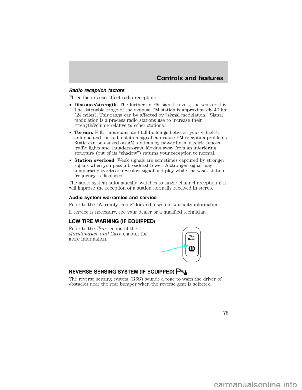
LOW TIRE WARNING (IF EQUIPPED)
Refer to theTiresection of the
Maintenance and Carechapter for
more information.
REVERSE SENSING SYSTEM (IF EQUIPPED)
The reverse sensing system (RSS) sounds a tone to warn the driver of
obstacles near the rear bumper when the reverse gear is selected.
Tire
Reset
Controls and features
75
Page 161 of 288
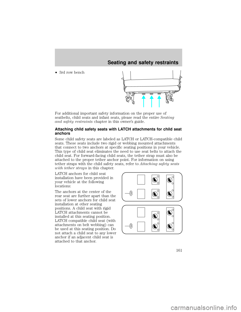
²3rd row bench
For additional important safety information on the proper use of
seatbelts, child seats and infant seats, please read the entireSeating
and safety restraintschapter in this owner's guide.
Attaching child safety seats with LATCH attachments for child seat
anchors
Some child safety seats are labeled as LATCH or LATCH-compatible child
seats. These seats include two rigid or webbing mounted attachments
that connect to two anchors at specific seating positions in your vehicle.
This type of child seat eliminates the need to use seat belts to attach the
child seat. For forward-facing child seats, the tether strap must also be
attached to the proper tether anchor point. For information on using
tether straps with the child safety seats, refer toAttaching safety seats
with tether strapsin this chapter.
LATCH anchors for child seat
installation have been provided in
your vehicle at the following
locations:
The anchors at the center of the
rear seat are further apart than the
sets of lower anchors for child seat
installation at other seating
positions. A child seat with rigid
LATCH attachments cannot be
installed at this seating position.
LATCH compatible child seat (with
attachments on belt webbing) can
be used at this seating position. Do
not attach a child seat to any lower
anchor if an adjacent child seat is
attached to that anchor.
Seating and safety restraints
161
Page 172 of 288
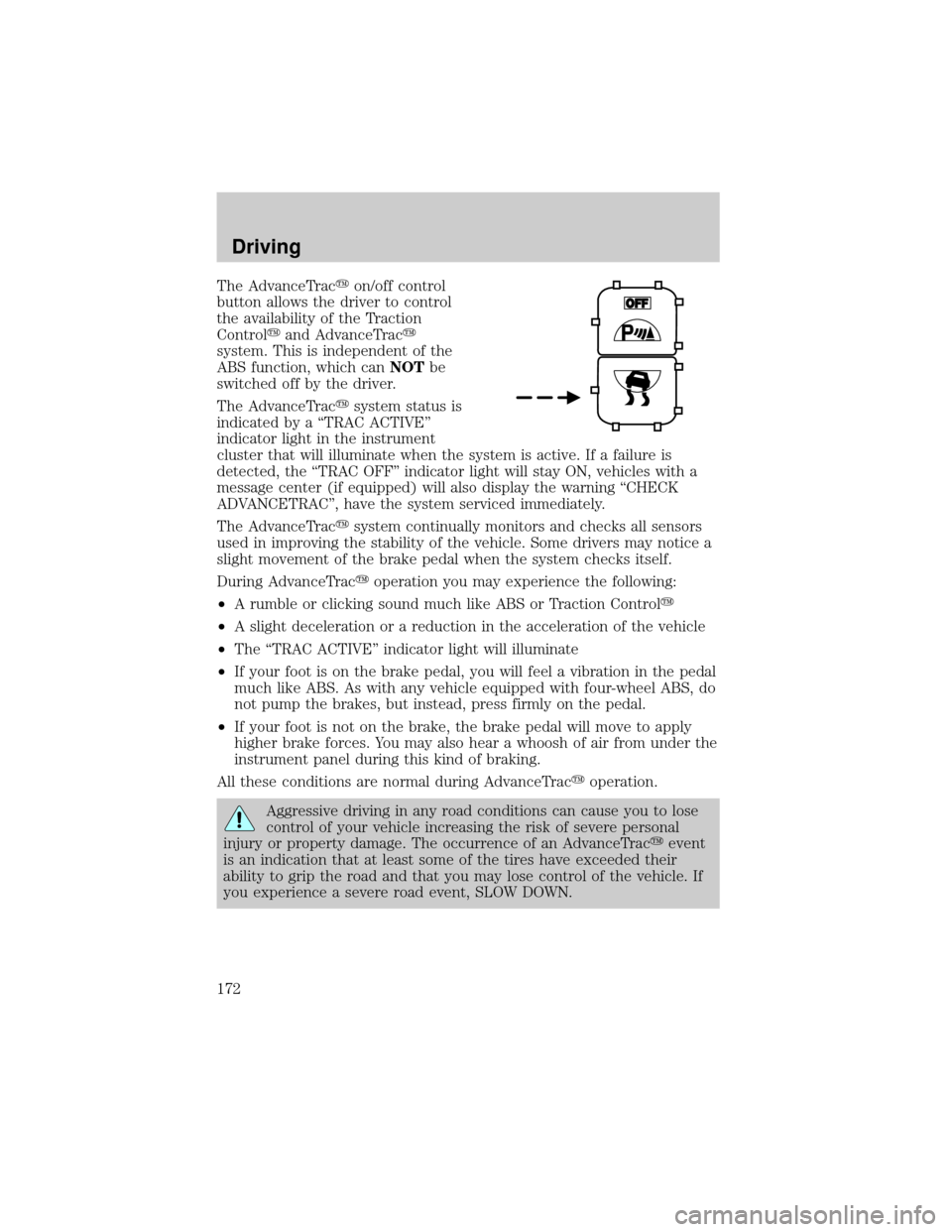
The AdvanceTracyon/off control
button allows the driver to control
the availability of the Traction
Controlyand AdvanceTracy
system. This is independent of the
ABS function, which canNOTbe
switched off by the driver.
The AdvanceTracysystem status is
indicated by a ªTRAC ACTIVEº
indicator light in the instrument
cluster that will illuminate when the system is active. If a failure is
detected, the ªTRAC OFFº indicator light will stay ON, vehicles with a
message center (if equipped) will also display the warning ªCHECK
ADVANCETRACº, have the system serviced immediately.
The AdvanceTracysystem continually monitors and checks all sensors
used in improving the stability of the vehicle. Some drivers may notice a
slight movement of the brake pedal when the system checks itself.
During AdvanceTracyoperation you may experience the following:
²A rumble or clicking sound much like ABS or Traction Controly
²A slight deceleration or a reduction in the acceleration of the vehicle
²The ªTRAC ACTIVEº indicator light will illuminate
²If your foot is on the brake pedal, you will feel a vibration in the pedal
much like ABS. As with any vehicle equipped with four-wheel ABS, do
not pump the brakes, but instead, press firmly on the pedal.
²If your foot is not on the brake, the brake pedal will move to apply
higher brake forces. You may also hear a whoosh of air from under the
instrument panel during this kind of braking.
All these conditions are normal during AdvanceTracyoperation.
Aggressive driving in any road conditions can cause you to lose
control of your vehicle increasing the risk of severe personal
injury or property damage. The occurrence of an AdvanceTracyevent
is an indication that at least some of the tires have exceeded their
ability to grip the road and that you may lose control of the vehicle. If
you experience a severe road event, SLOW DOWN.
Driving
172
Page 173 of 288
If you find yourself regularly experiencing AdvanceTracyevents,
you are driving too fast for conditions, you should reduce your
speed, and drive less aggressively. Speed Control should NOT be used
under these conditions. AdvanceTrac is limited by the laws of physics.
It is always possible to lose control of a vehicle due to inappropriate
driver inputs for the conditions. The occurrence of an AdvanceTracy
event is an indication that at least some of the tires have exceeded
their ability to grip the road; this may cause you to lose control of the
vehicle increasing the risk of severe personal injury or property
damage.
STEERING
Your vehicle is equipped with power steering. Power steering uses energy
from the engine to help steer the vehicle.
To prevent damage to the power steering pump:
²Never hold the steering wheel to the extreme right or the extreme left
for more than a few seconds when the engine is running.
²Do not operate the vehicle with a low power steering pump fluid level
(below the MIN mark on the reservoir).
If the power steering system breaks down (or if the engine is turned
off), you can steer the vehicle manually, but it takes more effort.
If the steering wanders or pulls, the condition could be caused by any of
the following:
²underinflated tire(s) on any wheel(s)
²uneven vehicle loading
²high crown in center of road
²high crosswinds
²wheels out of alignment
²loose or worn suspension components
AUTOMATIC TRANSAXLE OPERATION
Brake-shift interlock
This vehicle is equipped with a brake-shift interlock feature that prevents
the gearshift lever from being moved from P (Park) unless the brake
pedal is depressed.
Driving
173
Page 174 of 288
If the gearshift lever cannot be moved from P (Park) with the brake
pedal depressed, it is possible that a fuse has blown or the vehicle's
brakelamps are not operating properly. Refer toFuses and relaysin the
Roadside emergencieschapter.
Do not drive your vehicle until you verify that the brakelamps
are working.
If your vehicle gets stuck in mud or snow it may be rocked out by
shifting between forward and reverse gears, stopping between shifts, in a
steady pattern. Press lightly on the accelerator in each gear.
Do not rock the vehicle if the engine is not at normal operating
temperature or damage to the transaxle may occur.
Do not rock the vehicle for more than a few minutes or damage
to the transaxle and tires may occur or the engine may overheat.
Always set the parking brake fully and make sure the gearshift is
latched in P (Park). Turn off the ignition whenever you leave
your vehicle.
If the parking brake is fully released, but the brake warning lamp
remains illuminated, the brakes may not be working properly.
See your dealer or a qualified service technician.
Driving with an automatic overdrive transaxle with column
gearshift and O/D off switch
Your automatic transaxle electronically controls the shift feel by using an
adaptive learning strategy. This feature is designed to optimize shift
smoothness. It is normal for your transaxle to shift firmly during the first
few hundred kilometers (miles) of operation until the adaptive strategy
has been learned. The adaptive learning strategy is maintained by power
from the battery. When the battery is disconnected or a new battery is
installed, the transaxle must relearn its adaptive strategy. Optimal
shifting will resume within a few hundred kilometers (miles) of
operation.
Driving
174
Page 179 of 288
²GAWR (Gross Axle Weight Rating):Carrying capacity for each axle
system. The GAWR is specific to each vehicle and is listed on the
Safety Certification Label on the driver's door pillar.
²GCW (Gross Combined Weight):The combined weight of the
towing vehicle (including passengers and cargo) and the trailer.
²GCWR (Gross Combined Weight Rating):Maximum combined
weight of towing vehicle (including passengers and cargo) and the
trailer. The GCWR indicates the maximum loaded weight that the
vehicle is designed to tow.
²Maximum Trailer Weight Rating:Maximum weight of a trailer the
vehicle is permitted to tow. The maximum trailer weight rating is
determined by subtracting the vehicle curb weight for any required
option weight for trailer towing and the weight of the driver from the
GCWR for the towing vehicle.
²Maximum Trailer Weight:Maximum weight of a trailer the loaded
vehicle (including passengers and cargo) is permitted to tow. It is
determined by subtracting the weight of the loaded trailer towing
vehicle from the GCWR for the towing vehicle.
²Trailer Weight Range:Specified weight range that the trailer must
fall within that ranges from zero to the maximum trailer weight rating.
Remember to figure in the tongue load of your loaded trailer when
figuring the total weight.
Do not exceed the GVWR or the GAWR specified on the
certification label.
Do not use replacement tires with lower load carrying capacities than the
originals because they may lower the vehicle's GVWR and GAWR
limitations. Replacement tires with a higher limit than the originals do
not increase the GVWR and GAWR limitations.
The Safety Certification Label, found on the driver's door pillar, lists
several important vehicle weight rating limitations. Before adding any
additional equipment, refer to these limitations. If you are adding weight
to the front of your vehicle, (potentially including weight added to the
cab), the weight added should not exceed the front axle reserve capacity
(FARC). Additional frontal weight may be added to the front axle reserve
capacity provided you limit your payload in other ways (i.e. restrict the
number of passengers or amount of cargo carried).
Driving
179
Page 180 of 288

Always ensure that the weight of passengers, cargo and equipment being
carried is within the weight limitations that have been established for
your vehicle including both gross vehicle weight and Front and rear
gross axle weight rating limits. Under no circumstance should these
limitations be exceeded. Exceeding any vehicle weight rating limitation
could result in serious damage to the vehicle and/or personal injury.
Calculating the load your vehicle can carry/tow
1. Use the appropriate maximum gross combined weight rating (GCWR)
chart to find the maximum GCWR for your vehicle type and whether it's
equipped with a trailer tow option.
2. Weigh your vehicle as you customarily operate the vehicle without
cargo. To obtain correct weights, try taking your vehicle to a shipping
company or an inspection station for trucks.
3. Subtract your loaded vehicle weight from the maximum GCWR on the
following charts. This is the maximum trailer weight your vehicle can tow
and must fall below the maximum shown under maximum trailer weight
on the chart.
TRAILER TOWING
Trailer towing with your vehicle requires the optional trailer tow
electrical package and may require the use of an additional medium duty
trailer tow option package.
Trailer towing puts additional loads on your vehicle's engine,
transmission, axle, brakes, tires, and suspension. For your safety and to
maximize vehicle performance, be sure to use the proper equipment
while towing.
Follow these guidelines to ensure safe towing procedure:
²Stay within your vehicle's load limits. If exceeded, cargo should be
removed from the trailer and/or the vehicle until all weights are within
specified limits.
²Thoroughly prepare your vehicle for towing. Refer toPreparing to
towin this chapter.
²Use extra caution when driving while trailer towing. Refer toDriving
while you towin this chapter.
²Service your vehicle more frequently if you tow a trailer. Refer to
Special Operating Conditions in the scheduled maintenance guide.
Driving
180
Page 196 of 288
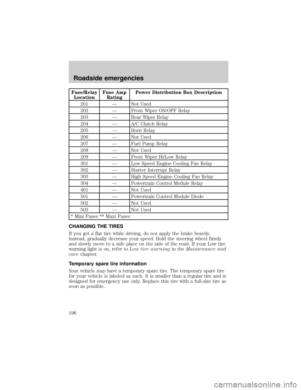
Fuse/Relay
LocationFuse Amp
RatingPower Distribution Box Description
201 Ð Not Used
202 Ð Front Wiper ON/OFF Relay
203 Ð Rear Wiper Relay
204 Ð A/C Clutch Relay
205 Ð Horn Relay
206 Ð Not Used
207 Ð Fuel Pump Relay
208 Ð Not Used
209 Ð Front Wiper Hi/Low Relay
301 Ð Low Speed Engine Cooling Fan Relay
302 Ð Starter Interrupt Relay
303 Ð High Speed Engine Cooling Fan Relay
304 Ð Powertrain Control Module Relay
401 Ð Not Used
501 Ð Powertrain Control Module Diode
502 Ð Not Used
503 Ð Not Used
* Mini Fuses ** Maxi Fuses
CHANGING THE TIRES
If you get a flat tire while driving, do not apply the brake heavily.
Instead, gradually decrease your speed. Hold the steering wheel firmly
and slowly move to a safe place on the side of the road. If your Low tire
warning light is on, refer toLow tire warningin theMaintenance and
carechapter.
Temporary spare tire information
Your vehicle may have a temporary spare tire. The temporary spare tire
for your vehicle is labeled as such. It is smaller than a regular tire and is
designed for emergency use only. Replace this tire with a full-size tire as
soon as possible.
Roadside emergencies
196
Page 230 of 288
Checking the wiper blades
If the wiper blades do not wipe properly, clean both the windshield and
wiper blades using undiluted windshield wiper solution or a mild
detergent. Rinse thoroughly with clean water. To avoid damaging the
blades, do not use fuel, kerosene, paint thinner or other solvents.
Changing the wiper blades
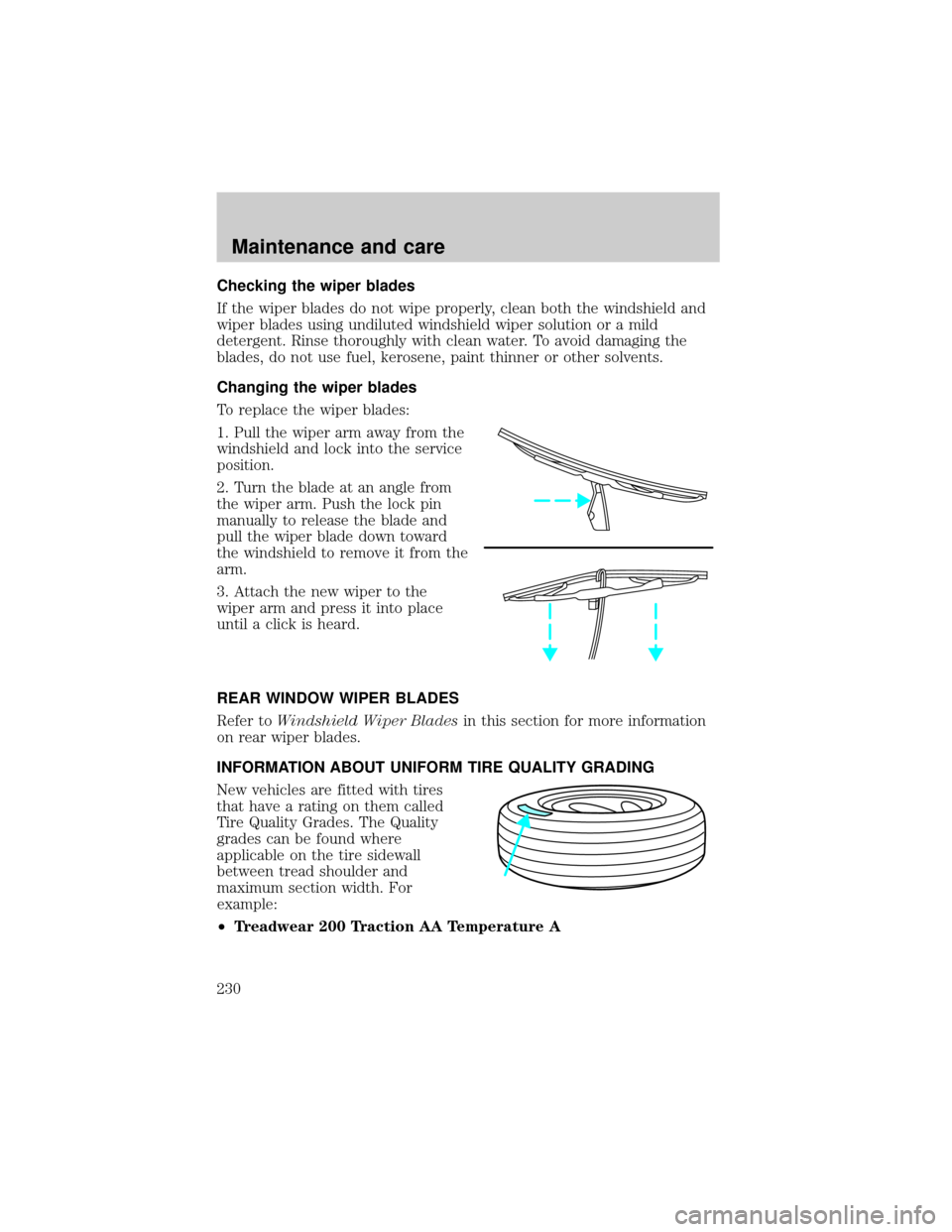
To replace the wiper blades:
1. Pull the wiper arm away from the
windshield and lock into the service
position.
2. Turn the blade at an angle from
the wiper arm. Push the lock pin
manually to release the blade and
pull the wiper blade down toward
the windshield to remove it from the
arm.
3. Attach the new wiper to the
wiper arm and press it into place
until a click is heard.
REAR WINDOW WIPER BLADES
Refer toWindshield Wiper Bladesin this section for more information
on rear wiper blades.
INFORMATION ABOUT UNIFORM TIRE QUALITY GRADING
New vehicles are fitted with tires
that have a rating on them called
Tire Quality Grades. The Quality
grades can be found where
applicable on the tire sidewall
between tread shoulder and
maximum section width. For
example:
²Treadwear 200 Traction AA Temperature A
Maintenance and care
230
Page 231 of 288
These Tire Quality Grades are determined by standards that the United
States Department of Transportation has set.
Tire Quality Grades apply to new pneumatic tires for use on passenger
cars. They do not apply to deep tread, winter-type snow tires,
space-saver or temporary use spare tires, tires with nominal rim
diameters of 10 to 12 inches or limited production tires as defined in
Title 49 Code of Federal Regulations Part 575.104(c)(2).
U.S. Department of Transportation-Tire quality grades:The U.S.
Department of Transportation requires Ford to give you the following
information about tire grades exactly as the government has written it.
Treadwear
The treadwear grade is a comparative rating based on the wear rate of
the tire when tested under controlled conditions on a specified
government test course. For example, a tire graded 150 would wear one
and one-half (1 1/2) times as well on the government course as a tire
graded 100. The relative performance of tires depends upon the actual
conditions of their use, however, and may depart significantly from the
norm due to variations in driving habits, service practices, and
differences in road characteristics and climate.
Traction AA A B C
The traction grades, from highest to lowest are AA, A, B, and C. Those
grades represent the tire's ability to stop on wet pavement as measured
under controlled conditions on specified government test surfaces of
asphalt and concrete. A tire marked C may have poor traction
performance.
The traction grade assigned to this tire is based on
straight-ahead braking traction tests, and does not include
acceleration, cornering, hydroplaning or peak traction characteristics.
Temperature A B C
The temperature grades are A (the highest), B, and C, representing the
tire's resistance to the generation of heat and its ability to dissipate heat
when tested under controlled conditions on a specified indoor laboratory
test wheel. Sustained high temperature can cause the material of the tire
to degenerate and reduce tire life, and excessive temperature can lead to
sudden tire failure. The grade C corresponds to a level of performance
Maintenance and care
231