FORD WINDSTAR 2003 2.G Owners Manual
Manufacturer: FORD, Model Year: 2003, Model line: WINDSTAR, Model: FORD WINDSTAR 2003 2.GPages: 240, PDF Size: 3.09 MB
Page 151 of 240
Canadian customers who require roadside assistance, call
1–800–665–2006.
If you need to arrange roadside assistance for yourself, Ford Motor
Company will reimburse a reasonable amount. To obtain reimbursement
information, U.S. Ford or Mercury vehicles customers call
1-800-241-3673; Lincoln vehicle customers call 1–800–521–4140.
Canadian customers who need to obtain reimbursement information, call
1–800–665–2006.
ROADSIDE COVERAGE BEYOND BASIC WARRANTY
In the United States, you may purchase additional roadside assistance
coverage beyond this period through the Ford Auto Club by contacting
your Ford or Lincoln Mercury dealer.
Similarly in Canada, for uninterrupted Roadside Assistance coverage, you
may purchase extended coverage prior to your Basic Warranty’s Roadside
Assistance expiring. For more information and enrollment, contact
1–877–294–2582 or visit our website at www.ford.ca.
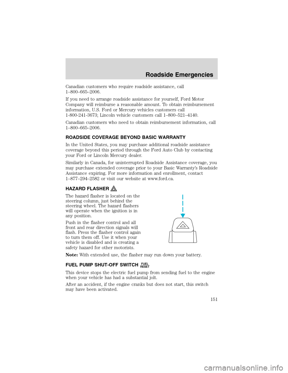
HAZARD FLASHER
The hazard flasher is located on the
steering column, just behind the
steering wheel. The hazard flashers
will operate when the ignition is in
any position.
Push in the flasher control and all
front and rear direction signals will
flash. Press the flasher control again
to turn them off. Use it when your
vehicle is disabled and is creating a
safety hazard for other motorists.
Note:With extended use, the flasher may run down your battery.
FUEL PUMP SHUT-OFF SWITCH
FUEL
RESET
This device stops the electric fuel pump from sending fuel to the engine
when your vehicle has had a substantial jolt.
After an accident, if the engine cranks but does not start, this switch
may have been activated.
Roadside Emergencies
151
Page 152 of 240
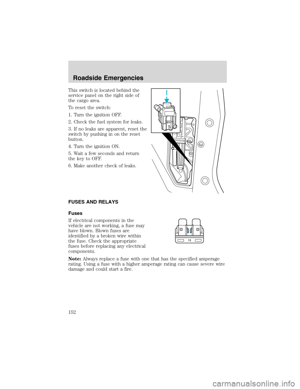
This switch is located behind the
service panel on the right side of
the cargo area.
To reset the switch:
1. Turn the ignition OFF.
2. Check the fuel system for leaks.
3. If no leaks are apparent, reset the
switch by pushing in on the reset
button.
4. Turn the ignition ON.
5. Wait a few seconds and return
the key to OFF.
6. Make another check of leaks.
FUSES AND RELAYS
Fuses
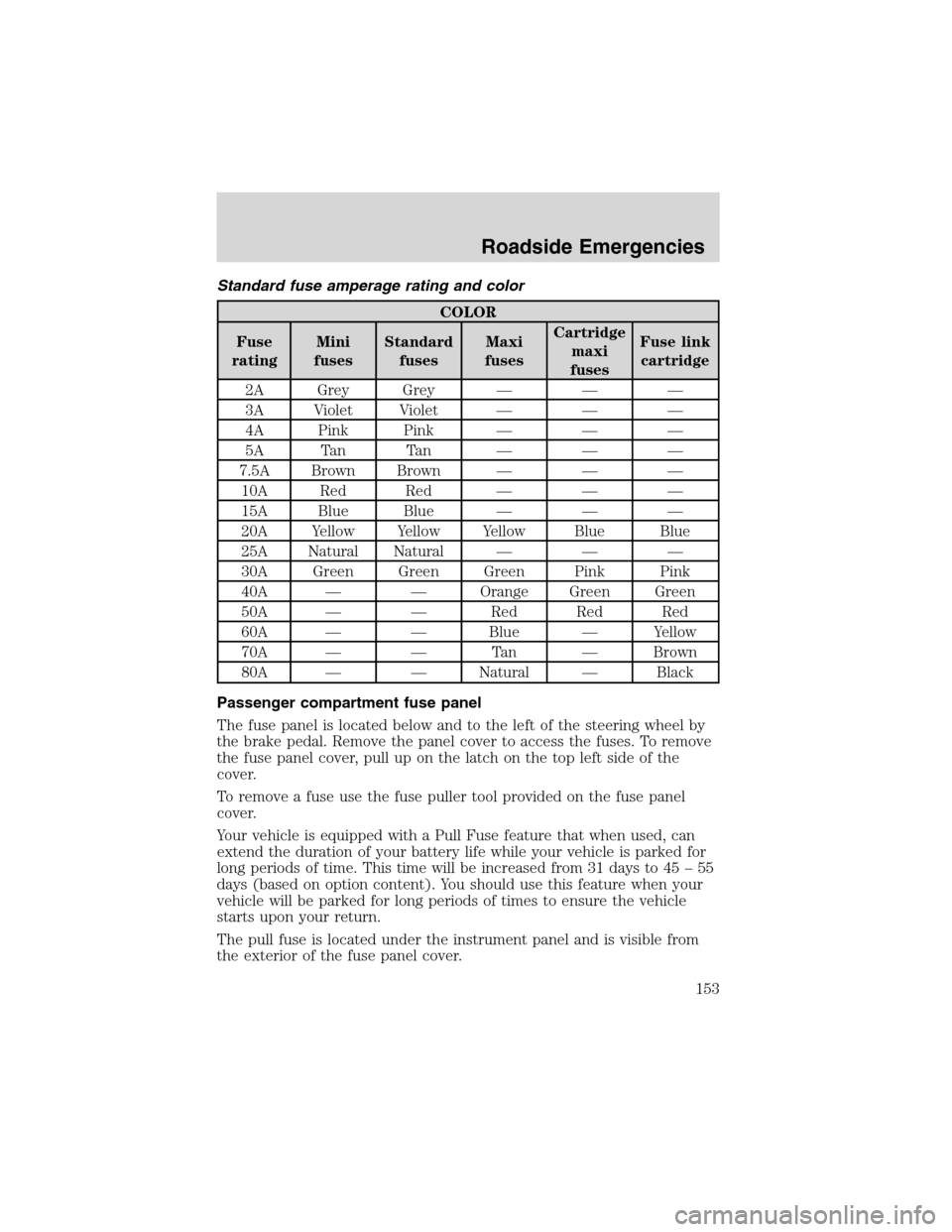
If electrical components in the
vehicle are not working, a fuse may
have blown. Blown fuses are
identified by a broken wire within
the fuse. Check the appropriate
fuses before replacing any electrical
components.
Note:Always replace a fuse with one that has the specified amperage
rating. Using a fuse with a higher amperage rating can cause severe wire
damage and could start a fire.
15
Roadside Emergencies
152
Page 153 of 240
Standard fuse amperage rating and color
COLOR
Fuse
ratingMini
fusesStandard
fusesMaxi
fusesCartridge
maxi
fusesFuse link
cartridge
2A Grey Grey———
3A Violet Violet———
4A Pink Pink———
5A Tan Tan———
7.5A Brown Brown———
10A Red Red———
15A Blue Blue———
20A Yellow Yellow Yellow Blue Blue
25A Natural Natural———
30A Green Green Green Pink Pink
40A——Orange Green Green
50A——Red Red Red
60A——Blue—Yellow
70A——Ta n—Brown
80A——Natural—Black
Passenger compartment fuse panel
The fuse panel is located below and to the left of the steering wheel by
the brake pedal. Remove the panel cover to access the fuses. To remove
the fuse panel cover, pull up on the latch on the top left side of the
cover.
To remove a fuse use the fuse puller tool provided on the fuse panel
cover.
Your vehicle is equipped with a Pull Fuse feature that when used, can
extend the duration of your battery life while your vehicle is parked for
long periods of time. This time will be increased from 31 days to 45–55
days (based on option content). You should use this feature when your
vehicle will be parked for long periods of times to ensure the vehicle
starts upon your return.
The pull fuse is located under the instrument panel and is visible from
the exterior of the fuse panel cover.
Roadside Emergencies
153
Page 154 of 240
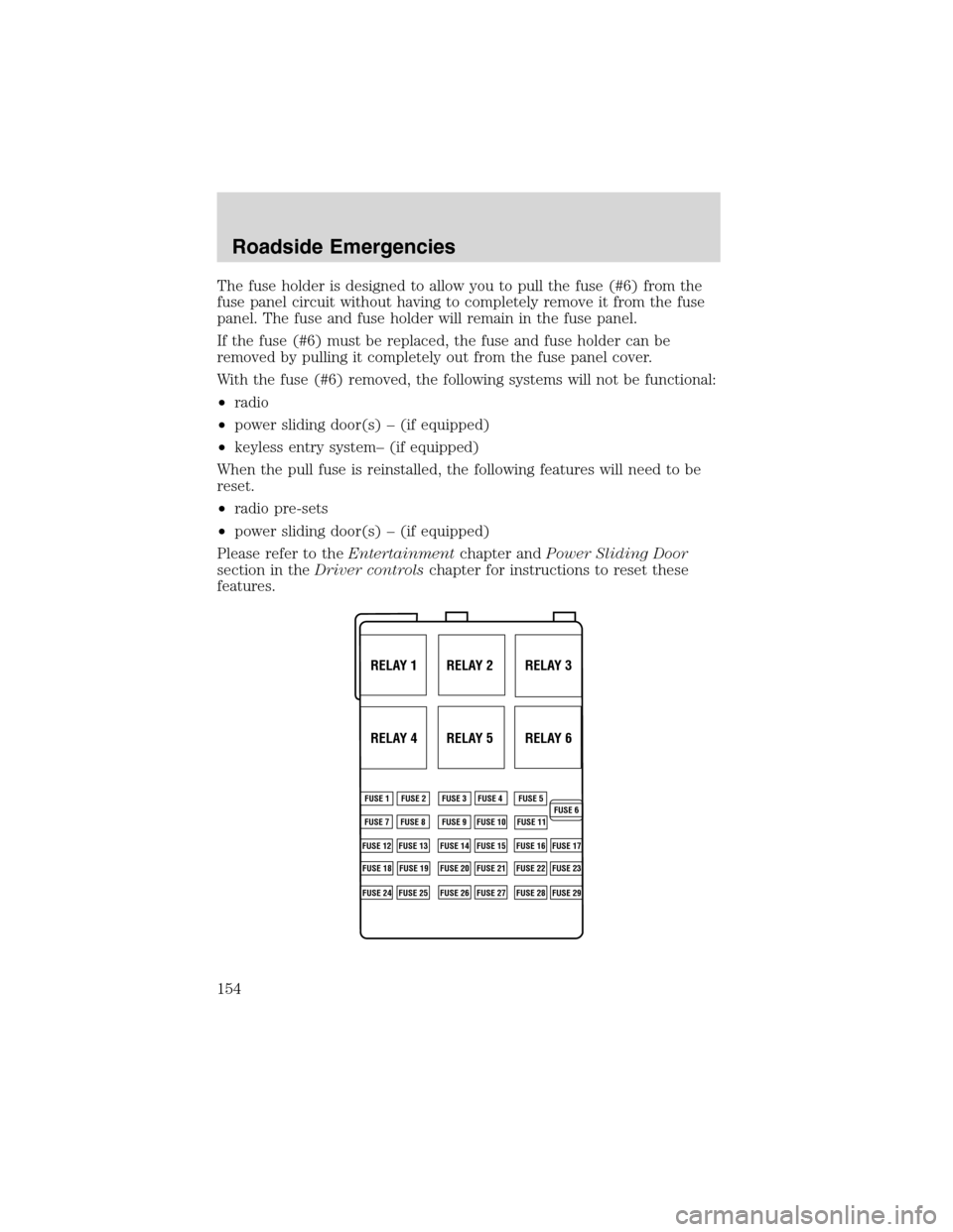
The fuse holder is designed to allow you to pull the fuse (#6) from the
fuse panel circuit without having to completely remove it from the fuse
panel. The fuse and fuse holder will remain in the fuse panel.
If the fuse (#6) must be replaced, the fuse and fuse holder can be
removed by pulling it completely out from the fuse panel cover.
With the fuse (#6) removed, the following systems will not be functional:
•radio
•power sliding door(s)–(if equipped)
•keyless entry system–(if equipped)
When the pull fuse is reinstalled, the following features will need to be
reset.
•radio pre-sets
•power sliding door(s)–(if equipped)
Please refer to theEntertainmentchapter andPower Sliding Door
section in theDriver controlschapter for instructions to reset these
features.
RELAY 1 RELAY 2 RELAY 3
RELAY 4 RELAY 5 RELAY 6
FUSE 1
FUSE 7
FUSE 12
FUSE 18
FUSE 24FUSE 8
FUSE 13
FUSE 19
FUSE 25FUSE 9
FUSE 14
FUSE 20
FUSE 26FUSE 10
FUSE 15
FUSE 21
FUSE 27FUSE 11
FUSE 16
FUSE 22
FUSE 28FUSE 17
FUSE 23
FUSE 29 FUSE 2 FUSE 3 FUSE 4 FUSE 5
FUSE 6
Roadside Emergencies
154
Page 155 of 240
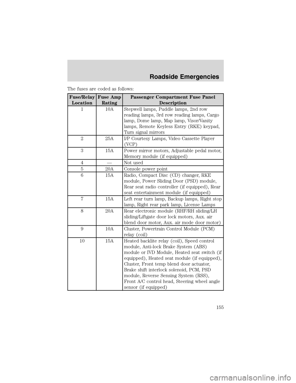
The fuses are coded as follows:
Fuse/Relay
LocationFuse Amp
RatingPassenger Compartment Fuse Panel
Description
1 10A Stepwell lamps, Puddle lamps, 2nd row
reading lamps, 3rd row reading lamps, Cargo
lamp, Dome lamp, Map lamp, Visor/Vanity
lamps, Remote Keyless Entry (RKE) keypad,
Turn signal mirrors
2 25A I/P Courtesy Lamps, Video Cassette Player
(VCP)
3 15A Power mirror motors, Adjustable pedal motor,
Memory module (if equipped)
4—Not used
5 20A Console power point
6 15A Radio, Compact Disc (CD) changer, RKE
module, Power Sliding Door (PSD) module,
Rear seat radio controller (if equipped), Rear
seat entertainment module (if equipped)
7 15A Left rear turn lamp, Backup lamps, Right stop
lamp, Right rear park lamp, License Lamps
8 20A Rear electronic module (RHF/RH sliding/LH
sliding/Liftgate door lock motors, Aux. air
blend door motor, Aux. air mode door motor)
9 10A Cluster, Powertrain Control Module (PCM)
relay (coil)
10 15A Heated backlite relay (coil), Speed control
module, Anti-lock Brake System (ABS)
module or IVD Module, Heated seat switch (if
equipped), Heated seat module (if equipped),
Cluster, Front temp blend door actuator,
Brake shift interlock solenoid, PCM, PSD
module, Reverse Sensing System (RSS),
Front A/C control head, Steering wheel angle
sensor (if equipped)
Roadside Emergencies
155
Page 156 of 240
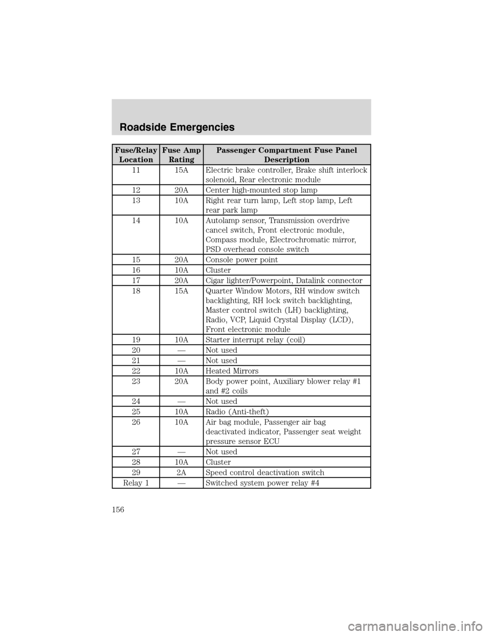
Fuse/Relay
LocationFuse Amp
RatingPassenger Compartment Fuse Panel
Description
11 15A Electric brake controller, Brake shift interlock
solenoid, Rear electronic module
12 20A Center high-mounted stop lamp
13 10A Right rear turn lamp, Left stop lamp, Left
rear park lamp
14 10A Autolamp sensor, Transmission overdrive
cancel switch, Front electronic module,
Compass module, Electrochromatic mirror,
PSD overhead console switch
15 20A Console power point
16 10A Cluster
17 20A Cigar lighter/Powerpoint, Datalink connector
18 15A Quarter Window Motors, RH window switch
backlighting, RH lock switch backlighting,
Master control switch (LH) backlighting,
Radio, VCP, Liquid Crystal Display (LCD),
Front electronic module
19 10A Starter interrupt relay (coil)
20—Not used
21—Not used
22 10A Heated Mirrors
23 20A Body power point, Auxiliary blower relay #1
and #2 coils
24—Not used
25 10A Radio (Anti-theft)
26 10A Air bag module, Passenger air bag
deactivated indicator, Passenger seat weight
pressure sensor ECU
27—Not used
28 10A Cluster
29 2A Speed control deactivation switch
Relay 1—Switched system power relay #4
Roadside Emergencies
156
Page 157 of 240
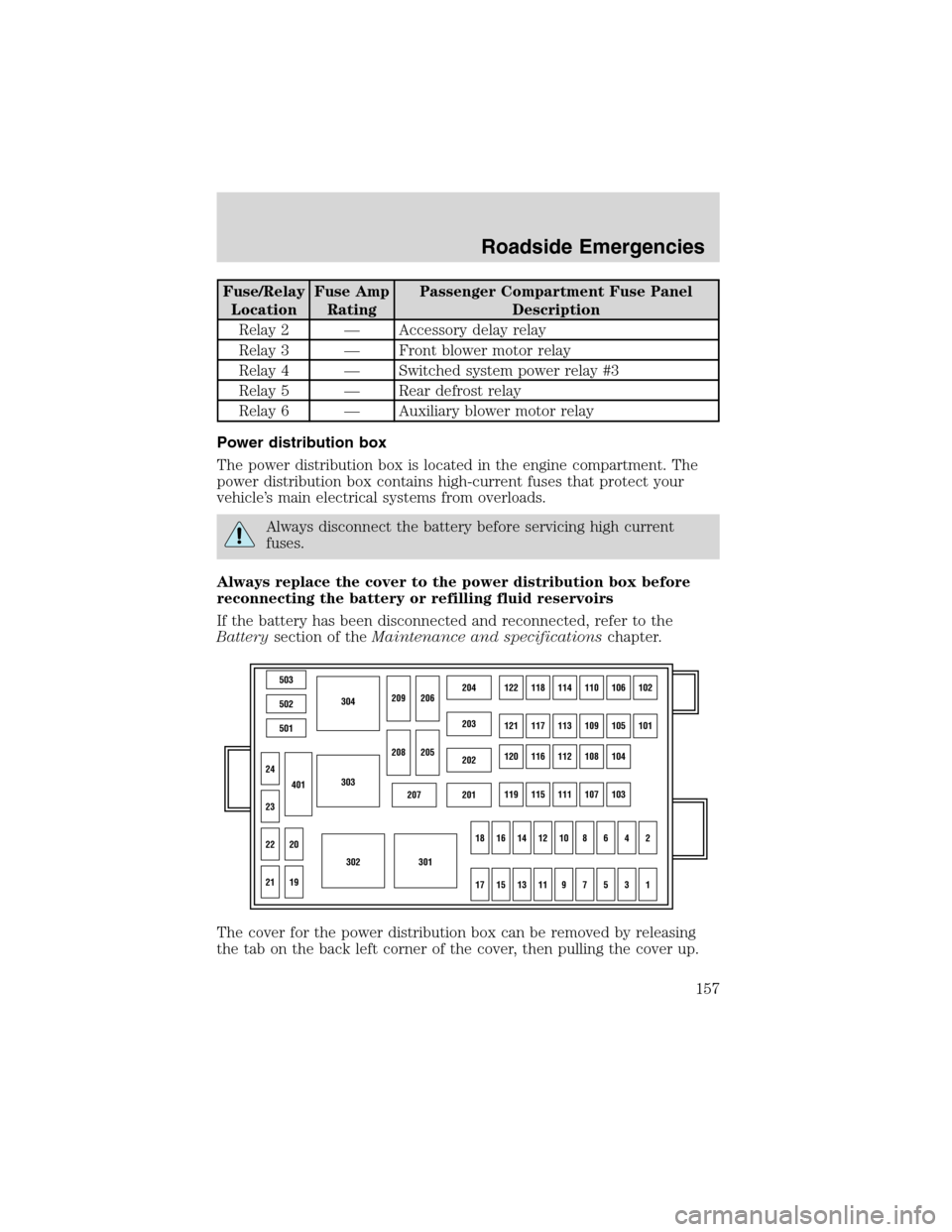
Fuse/Relay
LocationFuse Amp
RatingPassenger Compartment Fuse Panel
Description
Relay 2—Accessory delay relay
Relay 3—Front blower motor relay
Relay 4—Switched system power relay #3
Relay 5—Rear defrost relay
Relay 6—Auxiliary blower motor relay
Power distribution box
The power distribution box is located in the engine compartment. The
power distribution box contains high-current fuses that protect your
vehicle’s main electrical systems from overloads.
Always disconnect the battery before servicing high current
fuses.
Always replace the cover to the power distribution box before
reconnecting the battery or refilling fluid reservoirs
If the battery has been disconnected and reconnected, refer to the
Batterysection of theMaintenance and specificationschapter.
The cover for the power distribution box can be removed by releasing
the tab on the back left corner of the cover, then pulling the cover up.
503
304
303
302301
502
501
207201
202
203
204122118114110106102
121117113109105101
120116112108104
119115111107103
24
209206
208
18161412108642
1715131197531
205
23
22
21
401
20
19
Roadside Emergencies
157
Page 158 of 240
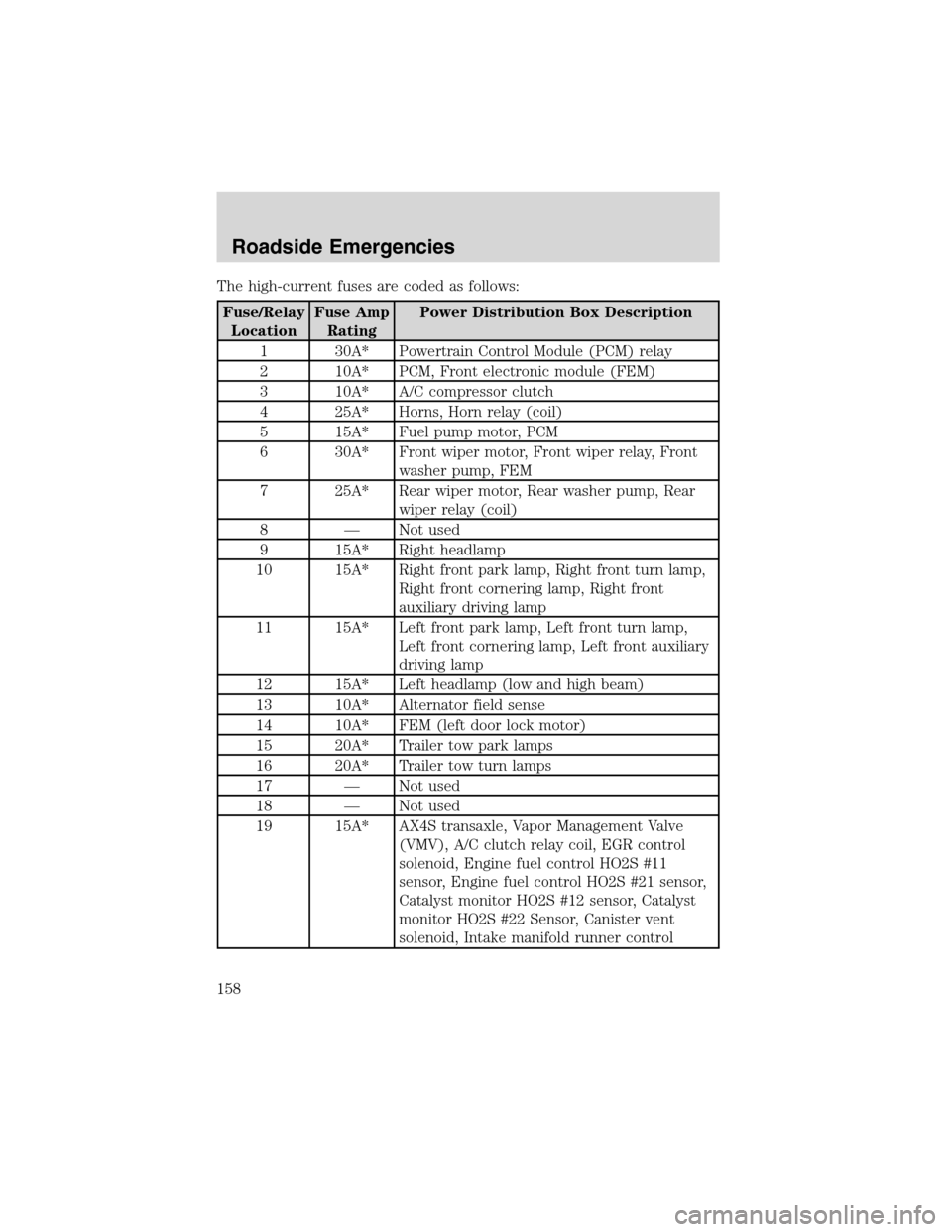
The high-current fuses are coded as follows:
Fuse/Relay
LocationFuse Amp
RatingPower Distribution Box Description
1 30A* Powertrain Control Module (PCM) relay
2 10A* PCM, Front electronic module (FEM)
3 10A* A/C compressor clutch
4 25A* Horns, Horn relay (coil)
5 15A* Fuel pump motor, PCM
6 30A* Front wiper motor, Front wiper relay, Front
washer pump, FEM
7 25A* Rear wiper motor, Rear washer pump, Rear
wiper relay (coil)
8—Not used
9 15A* Right headlamp
10 15A* Right front park lamp, Right front turn lamp,
Right front cornering lamp, Right front
auxiliary driving lamp
11 15A* Left front park lamp, Left front turn lamp,
Left front cornering lamp, Left front auxiliary
driving lamp
12 15A* Left headlamp (low and high beam)
13 10A* Alternator field sense
14 10A* FEM (left door lock motor)
15 20A* Trailer tow park lamps
16 20A* Trailer tow turn lamps
17—Not used
18—Not used
19 15A* AX4S transaxle, Vapor Management Valve
(VMV), A/C clutch relay coil, EGR control
solenoid, Engine fuel control HO2S #11
sensor, Engine fuel control HO2S #21 sensor,
Catalyst monitor HO2S #12 sensor, Catalyst
monitor HO2S #22 Sensor, Canister vent
solenoid, Intake manifold runner control
Roadside Emergencies
158
Page 159 of 240
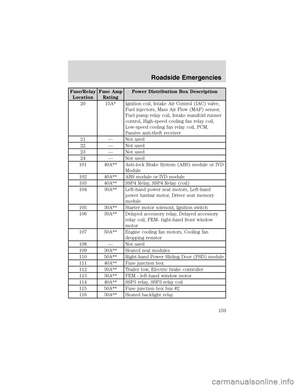
Fuse/Relay
LocationFuse Amp
RatingPower Distribution Box Description
20 15A* Ignition coil, Intake Air Control (IAC) valve,
Fuel injectors, Mass Air Flow (MAF) sensor,
Fuel pump relay coil, Intake manifold runner
control, High-speed cooling fan relay coil,
Low-speed cooling fan relay coil, PCM,
Passive anti-theft receiver
21—Not used
22—Not used
23—Not used
24—Not used
101 40A** Anti-lock Brake System (ABS) module or IVD
Module
102 40A** ABS module or IVD module
103 40A** SSP4 Relay, SSP4 Relay (coil)
104 30A** Left-hand power seat motors, Left-hand
power lumbar motor, Driver seat memory
module
105 30A** Starter motor solenoid, Ignition switch
106 30A** Delayed accessory relay, Delayed accessory
relay coil, FEM- right-hand front window
motor
107 50A** Engine cooling fan motors, Cooling fan
dropping resistor
108—Not used
109 30A** Heated seat modules
110 50A** Right-hand Power Sliding Door (PSD) module
111 40A** Fuse junction box
112 30A** Trailer tow, Electric brake controller
113 30A** FEM - left-hand window motor
114 40A** SSP3 relay, SSP3 relay coil
115 50A** Fuse junction box bus #2
116 30A** Heated backlight relay
Roadside Emergencies
159
Page 160 of 240
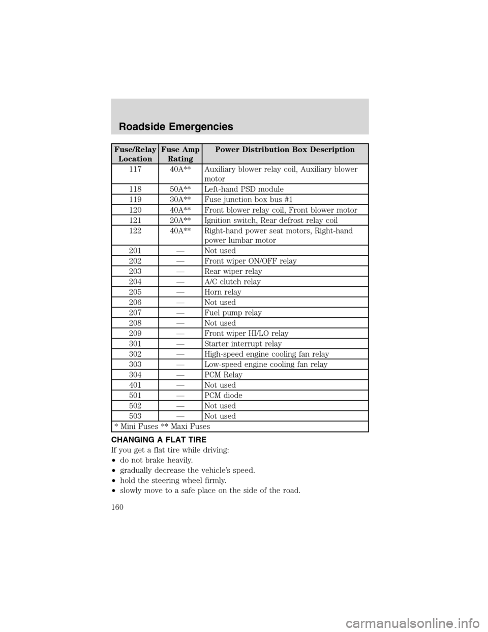
Fuse/Relay
LocationFuse Amp
RatingPower Distribution Box Description
117 40A** Auxiliary blower relay coil, Auxiliary blower
motor
118 50A** Left-hand PSD module
119 30A** Fuse junction box bus #1
120 40A** Front blower relay coil, Front blower motor
121 20A** Ignition switch, Rear defrost relay coil
122 40A** Right-hand power seat motors, Right-hand
power lumbar motor
201—Not used
202—Front wiper ON/OFF relay
203—Rear wiper relay
204—A/C clutch relay
205—Horn relay
206—Not used
207—Fuel pump relay
208—Not used
209—Front wiper HI/LO relay
301—Starter interrupt relay
302—High-speed engine cooling fan relay
303—Low-speed engine cooling fan relay
304—PCM Relay
401—Not used
501—PCM diode
502—Not used
503—Not used
* Mini Fuses ** Maxi Fuses
CHANGING A FLAT TIRE
If you get a flat tire while driving:
•do not brake heavily.
•gradually decrease the vehicle’s speed.
•hold the steering wheel firmly.
•slowly move to a safe place on the side of the road.
Roadside Emergencies
160