engine GEELY CK 2008 Owners Manual
[x] Cancel search | Manufacturer: GEELY, Model Year: 2008, Model line: CK, Model: GEELY CK 2008Pages: 392, PDF Size: 38.86 MB
Page 309 of 392
302Section 3 A/C controlling systemI. Introduction and CompositionIn order to ensure the effective opeation of the A/C system in any operating condition, some advanced
electric control devices are used to protect the A/C system in adverse engine operating condition.
The electrical control part consists of: A/C switch, relay, evaporator temperature sensor, water temperature
sensor, pressure switch, ECU...etc.
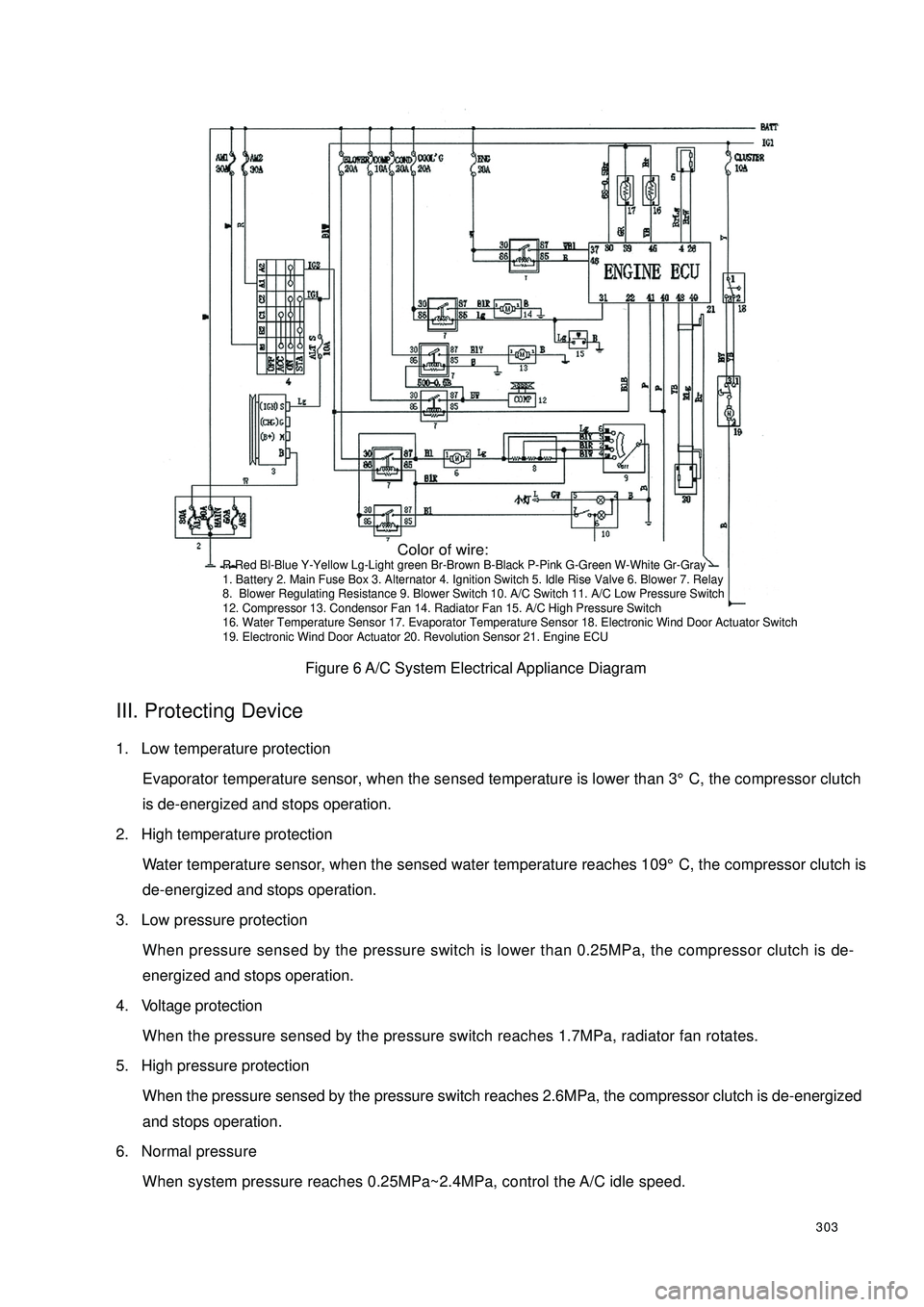
A/C system circuit diagram is shown in Figure 6.II. controlling system feature(1) The condenser fan's power is 90W;
(2) The performance of the condenser fan is controlled by ECU, pressure switch;
(3) Cut off the electrical power of the A/C compressor clutch when the water temperature reaches 109°C;
(4) Connect blower switch 9 to rotate the blower motor 6 to ensure A/C normal operation. Connect A/C
switch 10 to output A/C request signal to ECU.
(5) After ECU receives the request signal and the one from the evaporator temperature sensor 17, if the
engine is at idle, ECU first increases the engine speed to 950 ± 50r/min, lest the A/C operation enhance
the load and lower the engine speed or result in engine off. And then the ECU can respond. If the engine
is in accelerating condition, ECU does not respond immediately either, and respond 5 seconds later after
the end of the accelerating condition. ECU send out a A/C control signal from pin 22 to relay 7, command
the relay to suction in. With the low pressure switch 11 closed, the compressor 12 starts to work when the
magnetic clutch suction on. The condenser relay holds in and condenser blower 13 rotates. When high
pressure switch 15 is closed, have the relay 7 hold in and the water tank fan 14 rotates. When the water
temperature sensor 16's temperature is higher than 109°C, ECU shut off the output signal of the pin 22
and A/C stops operation.
(6) When the Refrigeration system pressure is over 1.7MPa, radiator fan will rotato. Disconnect A/C
compressor Refrigeration system power supply when the pressure is over 2.6MPa or less than 0.25MPa;
Page 310 of 392
303Figure 6 A/C System Electrical Appliance DiagramIII. Protecting Device1. Low temperature protection
Evaporator temperature sensor, when the sensed temperature is lower than 3°C, the compressor clutch
is de-energized and stops operation.
2. High temperature protection
Water temperature sensor, when the sensed water temperature reaches 109°C, the compressor clutch is
de-energized and stops operation.
3. Low pressure protection
When pressure sensed by the pressure switch is lower than 0.25MPa, the compressor clutch is de-
energized and stops operation.
4. Voltage protection
When the pressure sensed by the pressure switch reaches 1.7MPa, radiator fan rotates.
5. High pressure protection
When the pressure sensed by the pressure switch reaches 2.6MPa, the compressor clutch is de-energized
and stops operation.
6. Normal pressure
When system pressure reaches 0.25MPa~2.4MPa, control the A/C idle speed. Color of wire:R-Red Bl-Blue Y-Yellow Lg-Light green Br-Brown B-Black P-Pink G-Green W-White Gr-Gray
1. Battery 2. Main Fuse Box 3. Alternator 4. Ignition Switch 5. Idle Rise Valve 6. Blower 7. Relay
8. Blower Regulating Resistance 9. Blower Switch 10. A/C Switch 11. A/C Low Pressure Switch
12. Compressor 13. Condensor Fan 14. Radiator Fan 15. A/C High Pressure Switch
16. Water Temperature Sensor 17. Evaporator Temperature Sensor 18. Electronic Wind Door Actuator Switch
19. Electronic Wind Door Actuator 20. Revolution Sensor 21. Engine ECU
Page 313 of 392
3063. Check for leakage if the reading changes and vacuumize it again.
4. Refill the new HFC-134a refrigerant if the reading doesn’t change.
Fill the new HFC-134a refrigerant
1. Connect the intermediate pipe to the refrigerant steel jar.
2. Open the refrigerant steel jar valve.
3. Weigh the refrigerant steel jar to charge the right refrigerant volume (refrigerant refill 630g¡À20g).Warning:•Check for air leakage or any other leakage when refilling large amount of refrigerant into the
Refrigeration system. The operator is recommended to fill small amount of refrigerant first to
prevent the refrigerant from leakage, which will result in ozonosphere damage.•It is very dangerous to open the engine high pressure side valve if filling the refrigerant with
the service tank. The pressure in the service tank will rise during the operation, which will
result in the service tank explosion. The exploded mental fragment and the splashed refrigerant
will hurt the operator badly. Therefore, do close the high pressure side valve when the engine
is working.4. Open the manifold gauge low pressure side valve.
5. Close the manifold gauge low pressure side valve when the manifold gauge low pressure side reading is
increased to 0.098Mpa{1.0kgf/cm2}.
6. Check cooling pipeline/hose for leakage with leak detector.
•Proceed to step 8 if there is no leakage.
•Tighten the union joint if there is leakage at the loosened union joint and go to next step.
7. Re-check the leaked points.
•Go to next step if there is no leakage after tightening the union joint.
•If there is still leakage at the same union joint, drain refrigerant and repair the union joint. Repeat
the filling procedure and vacuum it.
8. Open the valve at the low pressure side of the manifold gauge. Fill the refrigerant until the refrigerant
tank weight from the one mentioned in Step 3 drop to 250g.
9. Close the valve at the low pressure side of the manifold gauge.
10. Start the engine and switch on A/C.
11. Open the valve at the low pressure side of the manifold gauge. Fill the refrigerant until the refrigerant
tank weight from the one mentioned in Step 3 to specified value.
12. Close the valve at the low pressure side of the manifold gauge and the valve of the refrigerant steel jar.
13. Stop the engine and A/C compressor.
Page 314 of 392

307Check For Leakage:
1. Using leak detector, check refrigerant steel jar for leakage.
•Go to Step 3 if there is no leakage.
•Tighten the union joint if there is leakage at the loosened union joint and go to next step.
2. Re-check the leaked points.
•Go to next step if there is no leakage after tightening the union joint.
•If there is still leakage at the same union joint, drain refrigerant and vacuum the union joint.
3. Disconnect the high and low pressure pipe at the refill valve.
4. Install the filling valve cap.
Check Refrigerant Pressure:
1. Install the manifold gauge.
2. Warm up the engine and run it with constant 1800rpm.
3. Set the rpm of the cooling fan to the HIGHEST.
4. Turn on the A/C switch.
5. Set to internal circulation mode.
6. Set the temperature control mode to the COLDEST.
7. Set to be ventilation mode.
8. Close all door and windows.
9. Measure the environment temperature and the reading of the high pressure side and low pressure side
from the manifold gauge.
•Shoot the Refrigeration system trouble as required if it is not as specified in the technical specification.
The Performance Inspection of the Refrigeration System:
1. Check refrigerant pressure.
•Go to next step if the pressure value is correct.
•Shoot the Refrigeration system trouble promptly if the pressure value is not as specified in the
technical specification.
2. Insert a thermometer into the middle vent port at the driver's side.
3. Warm up the engine and run it at the constant 1800rpm.
4. Set the rpm of the cooling fan to the HIGHEST.
5. Switch on A/C.
6. Set to internal circulation mode.
7. Set the temperature control mode to the COLDEST.
8. Set to Ventilation Mode.
9. Close all doors and windows.
10. Wait until A/C output temperature is constant. (When the environment temperature is 38°C, the temperature
at the middle ventilation port at the drivers side is 10°C~16°C. )
Page 317 of 392

3104. A/C Compressor Removal / Installation1. Disconnect the negative (--) terminal cable from the battery.
2. Drain the refrigerant from the system.
3. Detach the radiator.
4. Loose the drive belt and then remove the drive belt.Notice:•If anything moisture or any foreign matter enters into the Refrigeration system for circulation,
the cooling performance of the Refrigeration system will obviously deteriorate with abnormal
noise. Plug the port immediately after removing any cooling circulation component to prevent
anything moistur or any foreign matter from entering the circulation.5. Remove the compressor inlet and outlet pipe.
6. Removemagnetic clutch connector.
7. Remove the compressor.
8. The installation is in the reverse order of the removal.
9. Adjust the drive belt.
10. Check the Refrigeration system performance.5. The Condenser Removal / Installation1. Disconnect the negative (--) terminal cable from the battery.
2. Drain the refrigerant from the system.Notice:•If anything moisture or any foreign matter enters into the Refrigeration system for circulation,
the cooling performance of the Refrigeration system will obviously deteriorate with abnormal
noise. Plug the port immediately after removing any cooling circulation component to prevent
anything moistur or any foreign matter from entering the circulation.3. Remove the condenser inlet and outlet pipeline to prevent the compressor oil from splashing.
4. Remove condenser fan connector.
5. Remove the engine hood lock.
6. Remove the engine hood lock support brace.
7. Remove the condenser.
8. The installation is in the reverse order of the removal.
9. Check the Refrigeration system performance.The Condenser Installation Description:1. When installing the new condenser, it is recommended to fill certain SW-100 compressor oil into the
refrigerant circuit.Refill: (approximate)
20ml{20 cc }
Page 325 of 392

318Chapter 2 Inside & outside Trim and AccessorySection 1 Configuration Index(I) Outside Trim And Front Accessory1 Door handle 6 Windshield
Front fender
(See the engine hood adjustment)
Front bumper
(See front bumper
r em o v a l/ in s t allat io n )
The engine hood
(See the engine hood
r em o v a l/ in s t a llat io n )
Elec tric outs ide rear view mirror
(See elec tric outs ide rear view
m ir r o r r em o v a l/ in s t allat io n ) 5 Co w l v e n t g r ille 1 0Front mudguard skirt
4 9 Fuel fill port cap 2 Ra d ia t o r g r ill a s s em b ly 7
38
Page 331 of 392
324(II) Engine HoodEngine Hood Removal / Installation
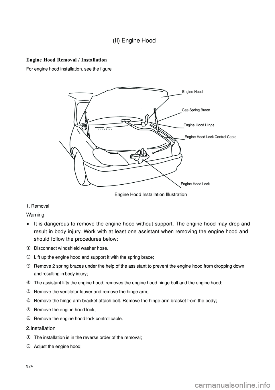
For engine hood installation, see the figure
1. Removal
Warning
•It is dangerous to remove the engine hood without support. The engine hood may drop and
result in body injury. Work with at least one assistant when removing the engine hood and
should follow the procedures below:
1Disconnect windshield washer hose.
2Lift up the engine hood and support it with the spring brace;
3Remove 2 spring braces under the help of the assistant to prevent the engine hood from dropping down
and resulting in body injury;
4The assistant lifts the engine hood, removes the engine hood hinge bolt and the engine hood;
5Remove the ventilator louver and remove the hinge arm;
6Remove the hinge arm bracket attach bolt. Remove the hinge arm bracket from the body;
7Remove the engine hood lock;
8Remove the engine hood lock control cable.
2.Installation
1The installation is in the reverse order of the removal;
2Adjust the engine hood;Engine HoodGas Spring BraceEngine Hood Hinge Engine Hood Lock Control CableEngine Hood LockEngine Hood Installation Illustration
Page 332 of 392
3253. Engine Hood Adjustment
Fix the engine hood to the engine hood hinge with bolts. the engine hood in vertical direction through the hinge
hole. Vertically adjust the front by adjusting the engine hood bumper and adjust the engine hood master lock
striker. The clearance tolerance is 1.0 mm-3.0 mm, while the flatness tolerance is 0 mm-1.0 mm.
(1) Open the engine hood
(2) Loose the bolt between the engine hood and the hinge
(3) Adjust the clearance between the engine hood and the front fender. Loose the bolt and move the engine
hood for adjustment.
(4) Close the engine hood
(5) Check for alignment
(6) Open the engine hood and adjust it as specified
(7) Adjust the engine hood bumper
(8) Check for alignment
(9) Adjust the engine hood master lock striker:
Loose 3 pin bolts on the engine hood lock. Move the engine hood lock for adjustment.
(10) Tighten the bolt between the engine and the hinge.
(11) Close the engine hood
4.Processing The Brace
Notice
•The air in the brace is of no color, no taste and no
poison.
(1) Wear the eye protection.
(2) Level the brace.
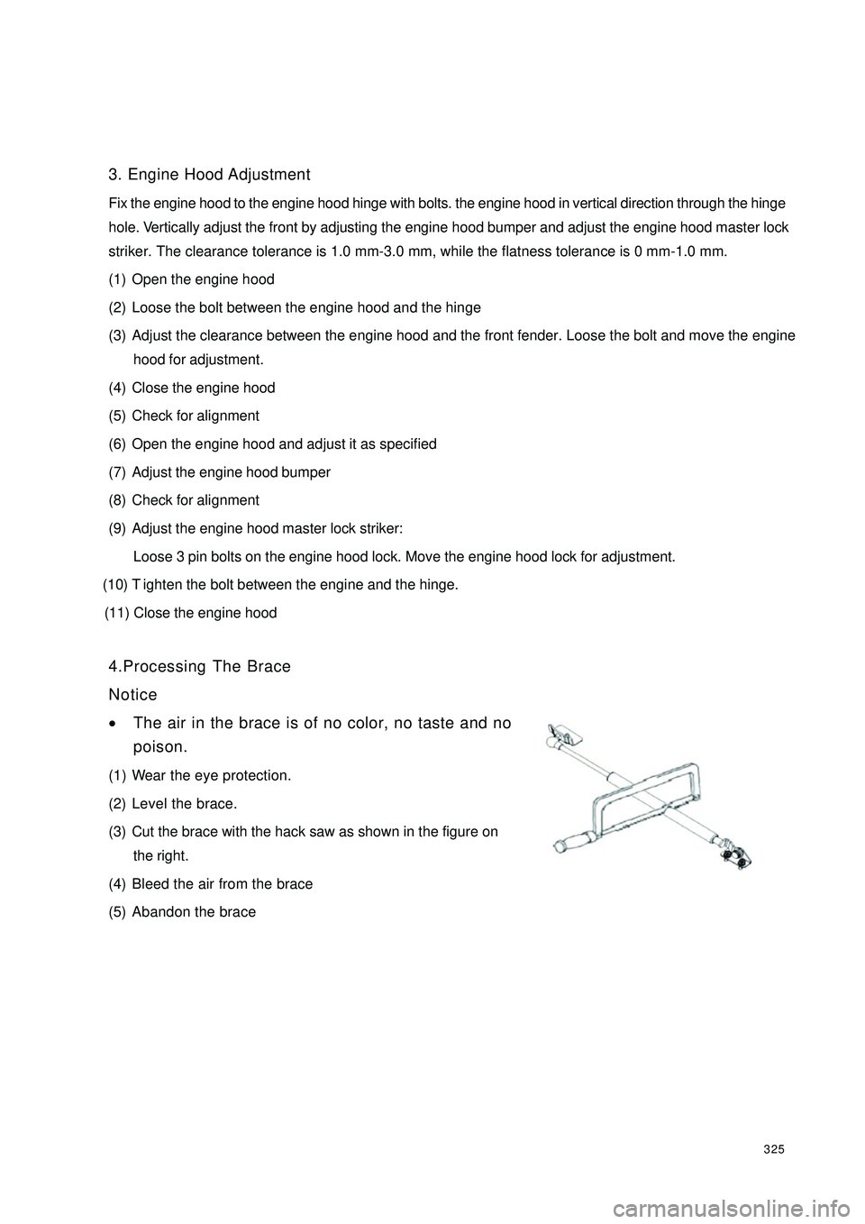
(3) Cut the brace with the hack saw as shown in the figure on
the right.
(4) Bleed the air from the brace
(5) Abandon the brace
Page 347 of 392

3403.Side Panel Removal/Installation
(1) Using the flat screwdriver wrapped with vinyl tape, disconnect the
clip.
(2) Pull the side panel towards yourself and remove the plate from the
instrument panel and remove the side panel.
(3) The installation is in the reverse order of the removal.
4.Steering Column Cover Removal/Installation
(1) Remove upper cover.
(2) Remove the ignition key.
(3) Remove the screw.
(4) Remove lower cover.
(5) The installation is in the reverse order of the removal.
5.Combination Instrument Panel Removal/Installation
(1) Remove the screw.
(2) Using the flat screwdriver wrapped with vinyl tape, disconnect the clip.
(3) Pull combination instrument panel towards yourself. Remove pillar.
(4) The installation is in the reverse order of the removal.
6.Lower End Shield Removal/Installation
(1) Using the flat screwdriver wrapped with vinyl tape, disconnect the
clip.
(2) Pull the lower end shield towards yourself and remove clipA and
plate B from the instrument panel and remove lower end shield.
(3) Disconnect the engine hood cable.
The installation is in the reverse order of the removal.
Page 356 of 392

349�VTake out the rear trunk carpet, spare tire cover board and the rear trunk miscelleaneous box. Screw the
spare tire press plate assembly to take out the spare tire.
2. Installation
1Clip the rear trunk inside trim onto the corresponding hole in the reserve order of the removal;
2Install the right rear and left rear combination lamp access hole cover;
3Install the right and left speaker grill to the rear partition inside trim with a cross screwdriver;
4Install the rear partition inside trim to the vehicle body;
5Install the high mounted stop lamp and the C- pillar upper inside trim.(XV) Engine Hood Inside TrimEngine Hood Inside Trim Diagram:
Engine Hood Inside Trim
1. Engine Hood Inside Trim 2. E-Clip
1. Removal
1Open the engine hood and gas spring;
2Remove the clip and remove the engine hood inside trim
2. Installation
1Open the installed engine hood and gas spring;
2Align the corresponding hole position in the the engine hood inside trim and press the clip in by hand.
2 1