AUX GEELY CK 2008 Workshop Manual
[x] Cancel search | Manufacturer: GEELY, Model Year: 2008, Model line: CK, Model: GEELY CK 2008Pages: 392, PDF Size: 38.86 MB
Page 6 of 392
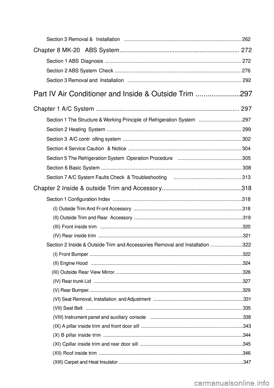
Section 3 Removal & Installation................................................................................... 262Chapter 8 MK-20 ABS System........................................................................ 2 7 2Section 1 ABS Diagnosis ................................................................................................. 272
Section 2 ABS System Check .......................................................................................... 276
Section 3 Removal and Installation................................................................................. 292Part IV Air Conditioner and Inside & Outside Trim ......................297Chapter 1 A/C System...................................................................................... 2 9 7Section 1 The Structure & Working Principle of Refrigeration System...............................297
Section 2 Heating System ................................................................................................ 299
Section 3 A/C controlling system.................................................................................... 302
Section 4 Service Caution & Notice................................................................................ 304
Section 5 The Refrigeration System Operation Procedure..............................................305
Section 6 Basic System .................................................................................................... 308
Section 7 A/C System Faults Check & Troubleshooting................................................ 313Chapter 2 Inside & outside Trim and Accessory................................................318Section 1 Configuration Index............................................................................................318(I) Outside Trim And Front Accessory.................................................................................318
(II) Outside Trim and Rear Accessory.................................................................................319
(III) Front inside trim..........................................................................................................320
(IV) Rear inside trim ............................................................................................................321Section 2 Inside & Outside Trim and Accessories Removal and Installation.......................322(I) Front Bumper..................................................................................................................322
(II) Engine Hood.................................................................................................................324
(III) Outside Rear View Mirror
(IV) Rear trunk Lid...............................................................................................................327
(V) Rear Bumper...................................................................................................................329
(VI) Seat Removal, Installation and Adjustment...................................................................331
(VII) Seat Belt.....................................................................................................................335
(VIII) Instrument panel and auxiliary console.....................................................................338
(IX) A pillar inside trim and front door sill ............................................................................343
(X) B pillar inside trim........................................................................................................344
(XI) Cpillar inside trim and rear door sill.............................................................................345
(XII) Roof inside trim
(XIII) Carpet and Heat Insulator.............................................................................................347 ...............................................................................................326
...........................................................................................................346
Page 18 of 392

11Component 2Figure 21Fan & Generator V-Belt
Vane-Type Pump V-Belt (V/ Power Steering)
V-Belt No.1Right Engine
Mounting InsulatorDoor AssemblySteering Column
AssemblyFront Shaft Hub Left NutLeft Front Speed Sensor Left Engine Mounting Bracket Steering Column Hole CoverHole Cover Steering Column Glove Compartment Front exhauxt pipe assembly
GasketGasket
One-off accessory
Page 93 of 392
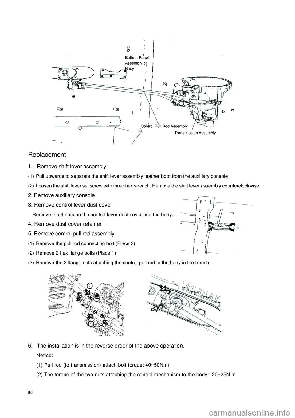
86Replacement1. Remove shift lever assembly
(1) Pull upwards to separate the shift lever assembly leather boot from the auxiliary console
(2) Loosen the shift lever set screw with inner hex wrench. Remove the shift lever assembly counterclockwise
2. Remove auxiliary console
3. Remove control lever dust cover
Remove the 4 nuts on the control lever dust cover and the body.
4. Remove dust cover retainer
5. Remove control pull rod assembly
(1) Remove the pull rod connecting bolt (Place 2)
(2) Remove 2 hex flange bolts (Place 1)
(3) Remove the 2 flange nuts attaching the control pull rod to the body in the trench
6. The installation is in the reverse order of the above operation.
Notice:
(1) Pull rod (to transmission) attach bolt torque: 40~50N.m
(2) The torque of the two nuts attaching the control mechanism to the body: 20~25N.mBottom Panel
Assembly of
BodyControl Pull Rod Assembly
Transmission Assembly
Page 95 of 392
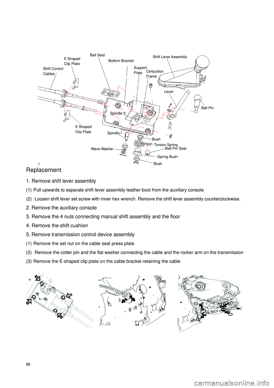
88Replacement1. Remove shift lever assembly
(1) Pull upwards to separate shift lever assembly leather boot from the auxiliary console
(2) Loosen shift lever set screw with inner hex wrench. Remove the shift lever assembly counterclockwise.
2. Remove the auxiliary console
3. Remove the 4 nuts connecting manual shift assembly and the floor
4. Remove the shift cushion
5. Remove transmission control device assembly
(1) Remove the set nut on the cable seal press plate
(2) Remove the cotter pin and the flat washer connecting the cable and the rocker arm on the transmission
(3) Remove the E-shaped clip plate on the cable bracket retaining the cableShift Control
CablesE Shaped
Clip PlateBall SeatShift Lever Assembly LeverBall PinSpindle IISpindle IE Shaped
Clip PlateWave WasherBushBushSpring BushBall Pin Seat Torsion Spring Support
Plate Bottom BracketConjuction
Frame
Page 162 of 392
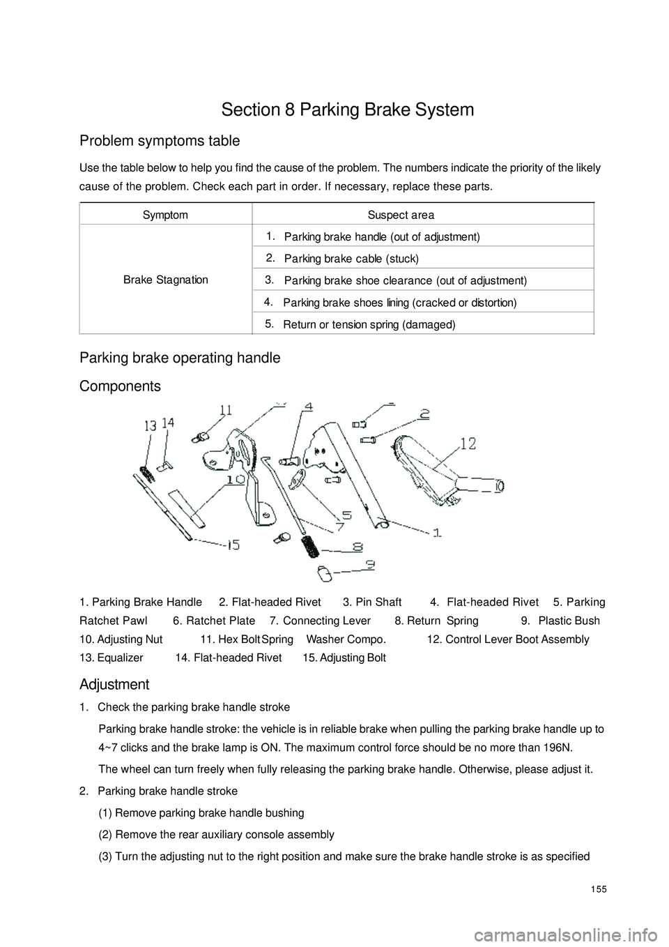
155Section 8 Parking Brake SystemProblem symptoms tableUse the table below to help you find the cause of the problem. The numbers indicate the priority of the likely
cause of the problem. Check each part in order. If necessary, replace these parts.Parking brake operating handle
Components1. Parking Brake Handle 2. Flat-headed Rivet 3. Pin Shaft 4. Flat-headed Rivet 5. Parking
Ratchet Pawl 6. Ratchet Plate 7. Connecting Lever 8. Return Spring 9. Plastic Bush
10. Adjusting Nut 11. Hex Bolt Spring Washer Compo. 12. Control Lever Boot Assembly
13. Equalizer14. Flat-headed Rivet15. Adjusting BoltAdjustment1. Check the parking brake handle stroke
Parking brake handle stroke: the vehicle is in reliable brake when pulling the parking brake handle up to
4~7 clicks and the brake lamp is ON. The maximum control force should be no more than 196N.
The wheel can turn freely when fully releasing the parking brake handle. Otherwise, please adjust it.
2. Parking brake handle stroke
(1) Remove parking brake handle bushing
(2) Remove the rear auxiliary console assembly
(3) Turn the adjusting nut to the right position and make sure the brake handle stroke is as specifiedSymptom Suspect area1. P a rking bra ke ha ndle (out of a djustme nt)2. Parking brake cable (stuck)3. Parking brake shoe clearance (out of adjustment)4. P a rking bra ke shoes lining (crac ke d or distortion)5. Return or tension spring (damaged) Brake Stagnation
Page 163 of 392
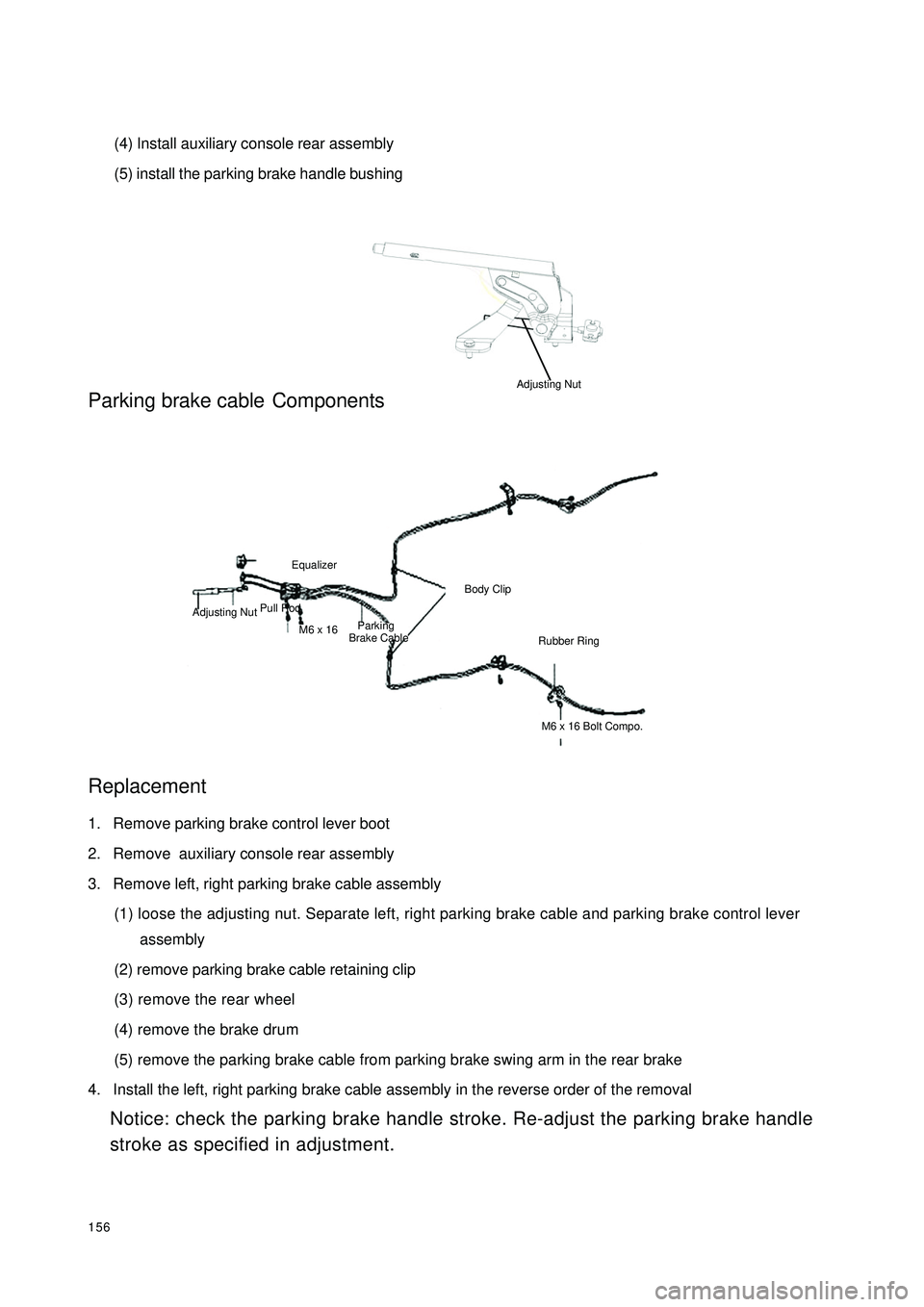
156(4) Install auxiliary console rear assembly
(5) install the parking brake handle bushingParking brake cableComponents
Replacement1. Remove parking brake control lever boot
2. Remove auxiliary console rear assembly
3. Remove left, right parking brake cable assembly
(1) loose the adjusting nut. Separate left, right parking brake cable and parking brake control lever
assembly
(2) remove parking brake cable retaining clip
(3) remove the rear wheel
(4) remove the brake drum
(5) remove the parking brake cable from parking brake swing arm in the rear brake
4. Install the left, right parking brake cable assembly in the reverse order of the removal
Notice: check the parking brake handle stroke. Re-adjust the parking brake handle
stroke as specified in adjustment.Pull RodEqualizerM6 x 16 Adjusting NutParking
Brake CableBody ClipRubber RingM6 x 16 Bolt Compo.Adjusting Nut
Page 269 of 392

262Section 3 Removal & InstallationI. SRS ELECTRONICAL CONTROL UNIT (ECU)1. Operations prior to Removal
(1) Turn the ignition switch OFF.
(2) Remove negative (-) terminal cable of the battery. Put it in a proper position or wrap it up with insulating
tape.
2. Removal procedures:
(1) Remove the central passage side cover plate (or remove auxiliary console).
(2) Remove the connectors to SRS ECU.
(3) Remove ECU.
3. Installation procedures:
(1) Install ECU.
(2) Install the connectors to SRS ECU.
(3) Install the central passage side cover plate (or install auxiliary console).
(4) Connect negative (-) terminal cable of the battery.
4. Key points for Installation:
(1) Install ECU.
(2) Check after installation.
1Turn the ignition switch ON.
2The warning light goes on within 6s, and then goes out.
(3) If the light doesn't go out, check the trouble and eliminate it.NOTICE1. Work must be started 60s after the negative (-) terminal cable is detached from battery. The detachednegative (-) terminal cable shall be protected with insulating tape for insulation.
2. Never attempt to dismantle or repair an ECU. If there is any trouble, replace the ECU with a new one.
3. Prevent the ECU from shock or vibration. If pitting, crack or distortion is found, replace the ECU with
a new one.
4. Every time an airbag is deployed, the ECU shall be replaced with a new one.
5. When disassembling or maintaining the parts around ECU, attention must be given to avoid contacting
the ECU.NOTICE
If the ECU cannot be installed correctly, the airbag will not act normally.
Page 319 of 392

312Introduction Of The Refrigeration Pipeline Installation:
1. It is recommended to fill some SW-100 compressor oil into the refrigerating circulation when installing a
new refrigeration pipe or cooling hose.
Refill: (approximate)
5ml{5 cc}: Refrigeration pipe
10ml{10 cc}: Condenser hose
2. Fill compressor oil to O-ring and other connecting points.
3. Tighten the connecting points.
Nuts union or slider joint type:
1. Tighten the nuts or the bolts of the connectiong
points by hand.
2. Tighten the connecting points with specified
torque wrench. It is connected with nuts. Tighten
the nuts with a wrench or a torque wrench.
3. Clip the slider block recess with pliers or other
similar tool and clamp the pipe used to connect
slider block. Tighten the bolt or the nuts at the
connecting points with a torque wrench.
7. A/C control panel removal / installation:
1. Disconnect the negative (--) terminal cable from the battery.
2. Remove the auxiliary console.
3. Disconnect the hot and cold air cable and airflow allocating cable.
4. Remove A/C control panel.
5. Disconnect blower switch connector.
6. Remove the lighting wire harness connector.
7. Remove the inside and outside circulation switch connector.
8. The installation is in the reverse order of the removal.Slider BuldgeSlider RecessionTorque Wrench
Page 327 of 392

320(III) Front inside trim613
7 Front door power window switc 14Elec tric outs ide rear view mirr or 5 Instrument panel end shield 12 Auxiliary console assembly 3 A/C panel assembl 10
411 1 A- pillar in s ide t r im 8
29
Low er en d s hield as s em b ly
Front row seat Front door insdie trim
Instrument panel assembly
Glove c ompartment as s embly
Steering column coverFront door sill inside trim
Front end of auxiliary c onsole
Page 345 of 392

338(VIII) Instrument panel and auxiliary console1. Instrument Panel Removal / Installation(1) Disconnect the negative (--) terminal cable from the
battery.
(2) Remove the instrument panel compartment.
(3) Remove the front and rear auxiliary console.
(4) Remove combination meter panel.
(5) Remove instrument cluster.
(6) Remove the steering column cover.
(7) Remove the undercover.
(8) Remove the steering column.
(9) Remove A pillar frame.
(10) Remove intermediate instrument panel.
(11) Remove right side shield.
(12) Remove left side shield.
(13) As to the vehicle installed with A/C control mechanism, disconnect the front A/C wire.
(See the removal and installation of A/C control mechanism)
(14) Disconnect the instrument panel wire harness connector.
(15) Remove the bolt.
(16) Take out the instrument panel from the open driver side door.
(17) The installation is in the reverse order of the removal.
Warning
It is dangerous to remove the instrument panel before supporting it. The instrument panel may
drop and result in body injury. Have at least one assistant for help to implement the procedures.
Remove the supporting pin from the vehicle body to remove the instrument panelPin