coolant temperature GEELY CK 2008 Workshop Manual
[x] Cancel search | Manufacturer: GEELY, Model Year: 2008, Model line: CK, Model: GEELY CK 2008Pages: 392, PDF Size: 38.86 MB
Page 59 of 392

52Chapter 6 Cooling System Inspection
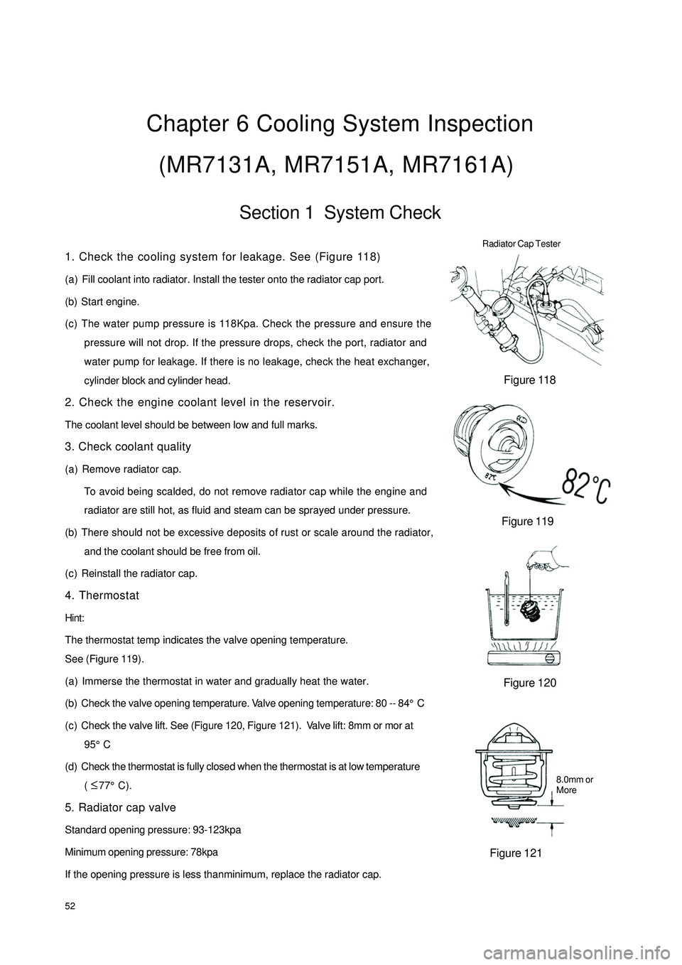
(MR7131A, MR7151A, MR7161A)Section 1 System Check1. Check the cooling system for leakage. See (Figure 118)
(a) Fill coolant into radiator. Install the tester onto the radiator cap port.
(b) Start engine.
(c) The water pump pressure is 118Kpa. Check the pressure and ensure the
pressure will not drop. If the pressure drops, check the port, radiator and
water pump for leakage. If there is no leakage, check the heat exchanger,
cylinder block and cylinder head.
2. Check the engine coolant level in the reservoir.
The coolant level should be between low and full marks.
3. Check coolant quality
(a) Remove radiator cap.
To avoid being scalded, do not remove radiator cap while the engine and
radiator are still hot, as fluid and steam can be sprayed under pressure.
(b) There should not be excessive deposits of rust or scale around the radiator,
and the coolant should be free from oil.
(c) Reinstall the radiator cap.
4. Thermostat
Hint:
The thermostat temp indicates the valve opening temperature.
See (Figure 119).
(a) Immerse the thermostat in water and gradually heat the water.
(b) Check the valve opening temperature. Valve opening temperature: 80 -- 84°C
(c) Check the valve lift. See (Figure 120, Figure 121). Valve lift: 8mm or mor at
95°C
(d) Check the thermostat is fully closed when the thermostat is at low temperature
( 77°C).
5. Radiator cap valve
Standard opening pressure: 93-123kpa
Minimum opening pressure: 78kpa
If the opening pressure is less thanminimum, replace the radiator cap.Figure 118
Figure 119
Figure 120
Figure 121 Radiator Cap Tester8.0mm or
More ≤
Page 60 of 392

536. Fan
(1) Check the cooling fan operation with low temperature (Lower than
83°C)
(a) Turn the ignition switch to “ON” position.
(b) Check that the cooling fan stops.
(c) Pull out the water temperature sensor connector. See (Figure
122)
(d) Connect the water temperature sensor to car body with the
wire and ground the wire.
(e) Check the cooling fan operation.
(f) Insert water temperature sensor connector.> 93°C
See (Figure 123)
(a) Start engine and make the coolant temp. higher than 93°C.
(b) Check that the cooling fan turns.
Replace it with water temperature switch if it doesn't run)
(3) Check the cooling fan. See (Figure 124)
(a) Disconnect the cooling fan connector.
(b) Connect the battery and ammeter to the connector.
(c) Check that the cooling fan rotates smoothly and check
the reading on the ammeter.
Standard amperage: 5.7 - 7.7A
(d) Reconnect the cooling fan connector.Disconnest
Figure 123
Figure 124 Figure 122
(2) Check the cooling fan operation with high temperature (over 93°C)Battery Amperometer
Page 82 of 392

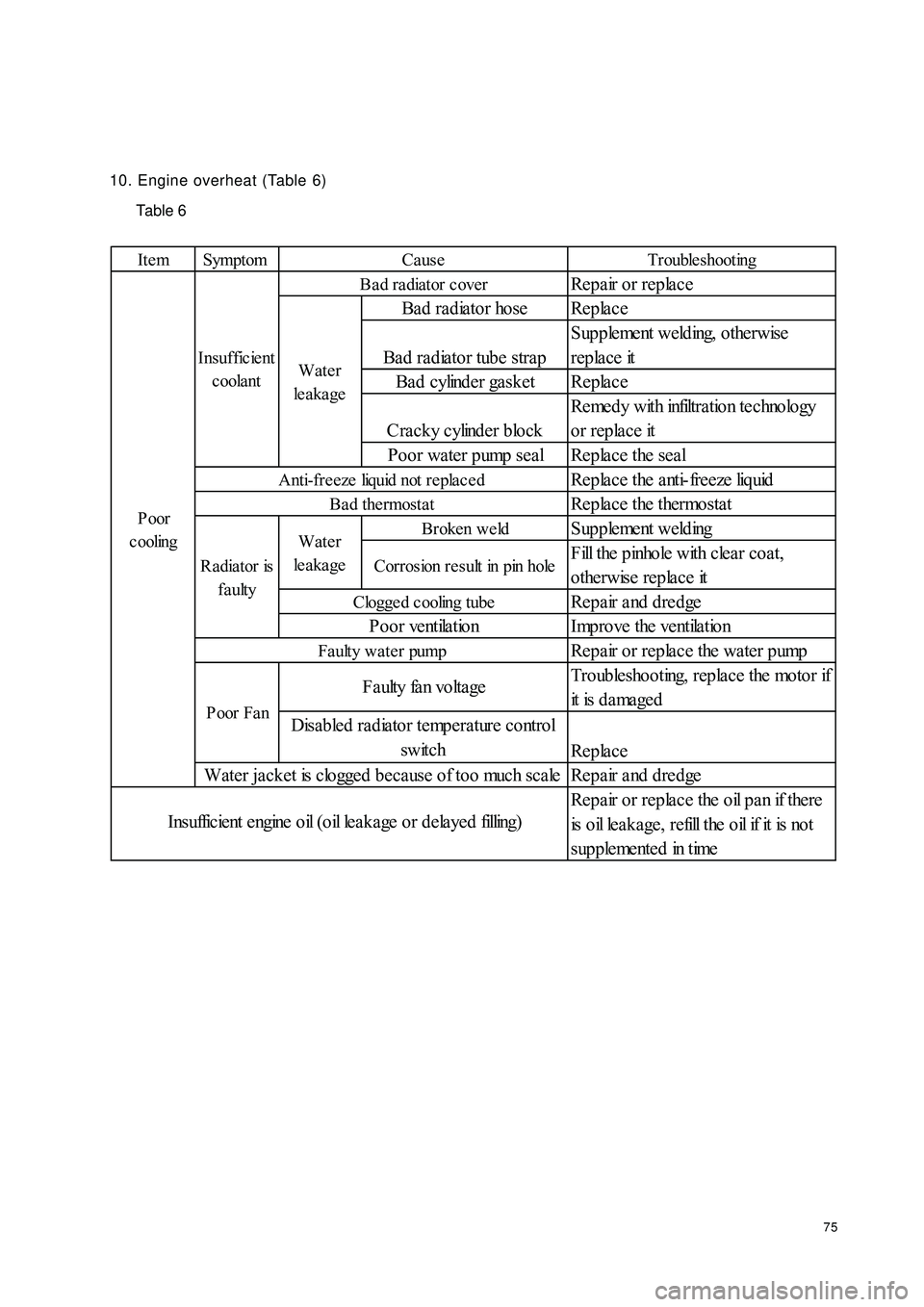
7510. Engine overheat (Table 6)
Table 6Ite m Symptom Trouble shootingRepair or replace
Bad radiator hose Replace
Bad radiator tube strapSupplement welding, otherwise
replace it
Bad cylinder gasket Replace
Cracky cylinder blockRemedy with infiltration technology
or replace it
Poor water pump seal Replace the seal
Replace the anti-freeze liquid
Replace the thermostatBroken we ldSupplement weldingCorrosion result in pin holeFill the pinhole with clear coat,
otherwise replace it
Repair and dredge
Improve the ventilation
Repair or replace the water pump
Troubleshooting, replace the motor if
it is d a ma ge d
Replace
Repair and dredge
Repair or replace the oil pan if there
is o il le a k a ge , r e fill t he o il if it is no t
s up p le me nt e d in t imeCause
Ba d ra diator c over
Clogge d cooling tubePoor ventilationWater
le a ka ge
Anti-fre eze liquid not repla ce d
Bad thermostat
Radiator is
faultyWater
le a ka ge Insufficient
coolantF a ulty fa n vo lta ge
Disabled radiator temperature control
switch
Water jacket is clogged because of too much scale
I ns uffic ie nt e ngine o il ( o il le a k a ge o r d e la ye d filling)P oor
c ooling
Poor FanFaulty water pump
Page 180 of 392

1732. DEFINITION OF MULTIPIN PLUG-IN TERMINALDefinition of Terminal Color of Harness
1Empty
2EPS VG
3Empty
4Empty
5Empty
6Empty
7Empty
8 Combination switch (Position lamp P
9 Speed sensor groun B
10 Speed sensor power sourc RY
11 Speed sensor signal outpu YR
12 Fuel senso B
13 Alte rna tor WR
14 Brake fluid level switc GR
15 Oil pressure switc YG
16 Re a r de frost YB
1 Rear fog lamp Gr
2 Engine ma lfunc tion GY
3 S e a t be lt s w it c h R
4 P owe r sourc e Y
5 Engine coolant temperature senso YW
6 Park switch G
7 Power source groun B
8 Power source groun B
9ABS R
10 SRS (Ma in) RY
11 Engine re volution signa l BBl
12 Live wire (Fire wire) WG
13 High be am la mp + RB
14 Low bea m - RW
15 SRS (Sub) RG
16 Empty Terminal No.
A
B
Page 190 of 392

1834. WATER TEMPERATURE GAUGE MALFUNCTION
CIRCUIT DIAGRAM
(a) Get the value of water temperature with the diagnosis tester
1Connect the diagnosis tester to the diagnosis interface
2Turn the ignition switch to ON
3Read the value of engine water temperature displayed on the diagnosis tester
Standard: The same with the actual engine coolant temperature.
Result and solution:
If it is normal, the water temperature gauge has no malfunction
If abnormal, Inspect the combination meter assembly
(b) Inspect the combination meter assembly
1Inspect resistance
�yRemove the combination meter assembly and disconnect connectors
�yInspect continuity between terminalsWater Temperature SensorCombined Meter Assembly
Water
Temperature
Signal
Page 306 of 392

299Section 2 Heating SystemHeating system uses mixed temperature adjustment which controls both cold and hot air and is featured in
outstanding temperature adjustment performance. The cold and hot air can be completely mixed at each
outlet and achieve continuous temperature adjustment. The air duct arrangement on the instrument panel is
shown in Figure 2. The air flow channel system is shown in Figure 3.I. Heating System Parameter and StructureHeating system uses water heating structure which uses the engine coolant as the heat source, leads the the
coolant into the heating radiator installed in the vehicle compartment and has the interior or exterior air blow
across the radiator with the blower to increase its temperature. The system consists of the blower assembly,
heating control assembly and heater assembly.Figure 2 Heating Duct ArrangementInside and Outside Air Switch Door Outdoor AirIndoor AirDefoggerIntermidiate outletHeaterBlower MotorEvaporatorAir Mix DoorHeating RadiatorFigure 3 Air Flow Channel System Illustration