fuse GEELY CK 2008 Workshop Manual
[x] Cancel search | Manufacturer: GEELY, Model Year: 2008, Model line: CK, Model: GEELY CK 2008Pages: 392, PDF Size: 38.86 MB
Page 48 of 392
41Chapter 4 Fuel System
(MR7131A, MR7151A, MR7161A)Section 1 Check Fuel System Pressure1. Remove the fuel tank from the vehicle
2. Check the fuel pump running
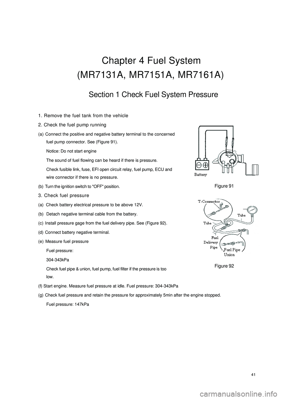
(a) Connect the positive and negative battery terminal to the concerned
fuel pump connector. See (Figure 91).
Notice: Do not start engine
The sound of fuel flowing can be heard if there is pressure.
Check fusible link, fuse, EFI open circuit relay, fuel pump, ECU and
wire connector if there is no pressure.
(b) Turn the ignition switch to "OFF" position.
3. Check fuel pressure
(a) Check battery electrical pressure to be above 12V.
(b) Detach negative terminal cable from the battery.
(c) Install pressure gage from the fuel delivery pipe. See (Figure 92).
(d) Connect battery negative terminal.
(e) Measure fuel pressure
Fuel pressure:
304-343kPa
Check fuel pipe & union, fuel pump, fuel filter if the pressure is too
low.
(f) Start engine. Measure fuel pressure at idle. Fuel pressure: 304-343kPa
(g) Check fuel pressure and retain the pressure for approximately 5min after the engine stopped.
Fuel pressure: 147kPaFigure 91Figure 92
Page 72 of 392
65g. Ignition system failure;
h. Low engine compression pressure.
(3) Diagnosis and Troubleshooting
a. First, check the fuel tank for fuel level, turn on the ignition switch, if fuel gauge pointer does not
move or fuel level warning lamp lights, then the fuel tank is empty, fuel shall be filled at this time.
b. Check that the electrical fuel pump for operation. Remove the fuel tank, you may use a wire to
connect the two jacks of the fuel pump for short, then turn on the ignition switch. The fuel pump
operation sound shall be able to be heard from the fuel tank nozzle or fuel flow can be felt with hand
pinching the tube; or remove the return hose on the fuel pressure regulator, check that the fuel
flows out; Direct judgment can be made if it is equipped with fuel pressure gage.
If electrical fuel pump is inoperative, check whether the main fuse, main relay, fuel pump relay,
fuel pump control circuit and ECU are OK. If all of them are OK, check fuel pump circuit for open,
short or damaged check valve. Repair or replacement shall be made when problems are found.
c. If there is no injection sound in injector, check injector control circuit for fault. You may use a
testing lamp with big resistance to be connected to the injector wiring connector, turn on the ignition
switch. If the testing lamp lights up, it indicates that the injector has been damaged and shall be
replaced; if the testing lamp does not light up, check whether the main fuse, EFI relay, fuse, ignition
switch and ECU terminal are OK, repair or replace them if they are not OK.
d. If there is low fuel pressure, the injection amount would be small and the engine won't start, you
should check the fuel filter for block and fuel pump safety valve for damage and check whether the
fuel pressure regulator is within the normal range, otherwise those components shall be repaired or
replaced.
e. Electric injection engine normally spot contact start the engine.
f. Check for open in the throttle position sensor (TPS) circuit.
g. Check whether there is Diagnostic Trouble Code (DTC), if there is, check it by the DTC; if there
is not, check the high voltage spark for intensity, if it is too weak, check spark plug, high voltage
wire, high voltage coil, distributor cover for faults, if there are faults, repair or replace them.
h. Check the compression pressure in the cylinder, insert the compression pressure gauge into the
spark plug hole, completely open the throttle, measure the compression pressure while starting the
engine. If the compression pressure is less than 980kPa when engine speed is more than 250r/min,
remove and inspect the engine and troubleshoot it.
3. The engine cranks but can not start
(1) Symptom
When starting the engine, starter can crank the engine but fail to start the engine.
(2) Causes:
a. Ignition advance angle is unfavorable;
b. Ignition is out of sequence, there is misfire;
c. High voltage spark is too weak;
d. The fuel pressure is too low;
e. fuel pressure regulator leakage;
Page 164 of 392
157Part III Electrical EquipmentChapter 1 SurveyThis part refers to the electrical repair of the Free Cruiser, and analyzes the faults from every system. Then
some practicable diagnosis procedure and repair ways are given.I. HAND-HELD TESTER1. Before the tester is used, a through reading of the Tester Operation Manual is commended.
2. Connect the tester to the diagnosis interface with a wire. Turn the ignition switch ON. At this time, if the
tester and ECU control system cannot communicate, the vehicle or the tester may have faults.
(1) Connect the tester lead wire to another vehicle. If the communication is normal, inspect the vehicle
diagnosis Busline or power supply circuit.
(2) If it still cannot communicate when connecting to the other vehicles, it may have faults on tester itself.
Consult the self-inspecting procedure described on the Tester Operation ManualII. HOW TO PROCEED WITH TROUBLESHOOTINGThe basic operation procedure for troubleshooting is as follows.
1. Customer fault analysis
(a) Ask the customer for the conditions and environment when faults happen.
2. Confirm the fault symptoms, and check the DTCs and storage data.
(a) Check the battery positive voltage (Voltage: 10 - 14V when the engine is stopped.)
(b) Inspect the harness, connector and fuse for open and short, etc. by their appearance.
(c) Warm up the engine temperature to the normal operation temperature.
(d) Confirm the fault symptoms and check the DTCs.
(e) Confirm the test procedure for the parts or systems that need checking.
3. Circuit or part inspection
4. Repair
5. Test for checking
(a) After the repair is completed, verify if the fault has been removed.
(If the fault has not appeared yet, a verifying test should be done under the same conditions and environment
when the fault first occurred.)
Page 169 of 392
1622. INSPECT STARTER NO-LOAD
(a) Connect the magnet exciting coil and the terminal.
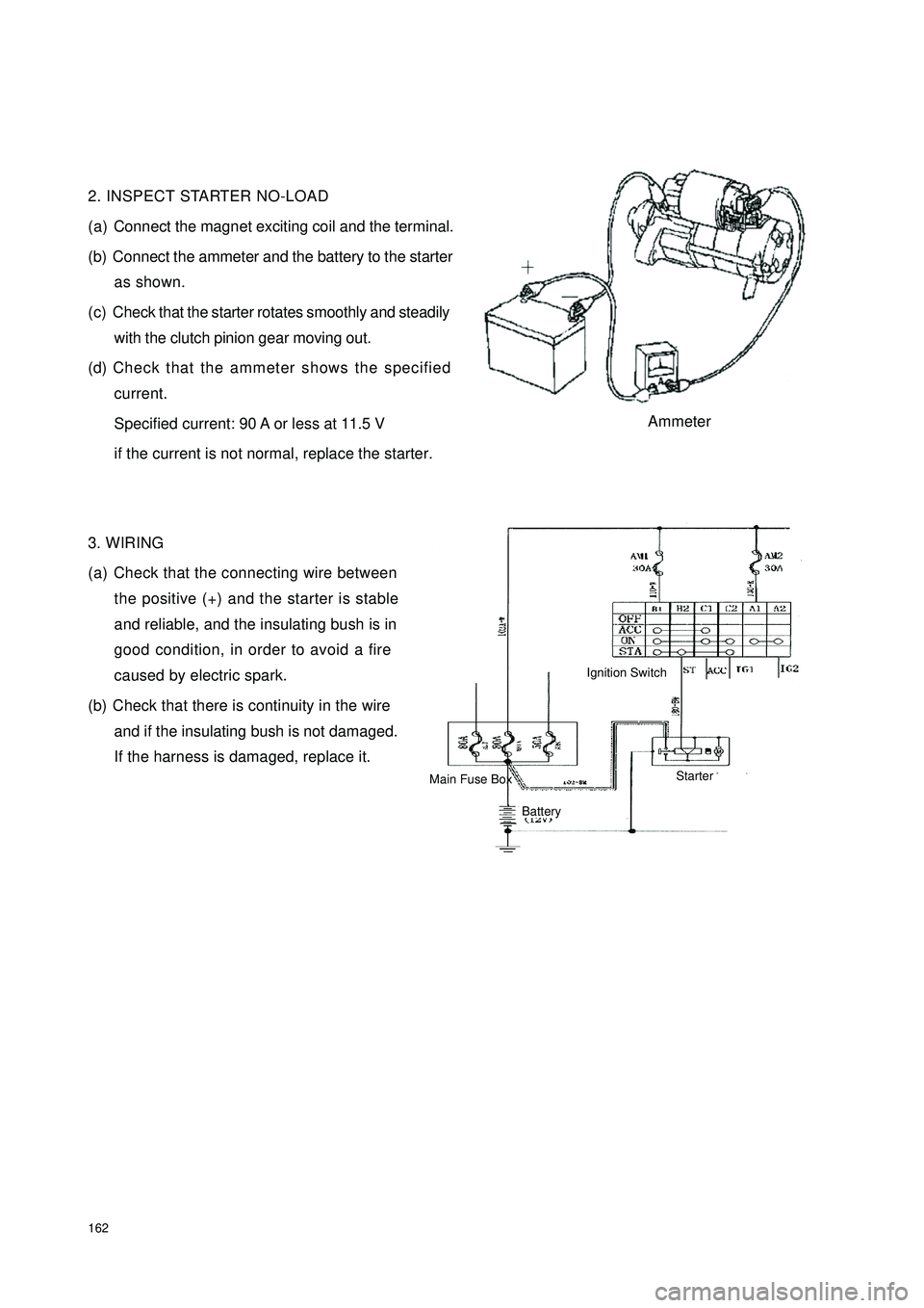
(b) Connect the ammeter and the battery to the starter
as shown.
(c) Check that the starter rotates smoothly and steadily
with the clutch pinion gear moving out.
(d) Check that the ammeter shows the specified
current.
Specified current: 90 A or less at 11.5 V
if the current is not normal, replace the starter.
3. WIRING
(a) Check that the connecting wire between
the positive (+) and the starter is stable
and reliable, and the insulating bush is in
good condition, in order to avoid a fire
caused by electric spark.
(b) Check that there is continuity in the wire
and if the insulating bush is not damaged.
If the harness is damaged, replace it.AmmeterIgnition SwitchBattery Main Fuse BoxStarter
Page 173 of 392
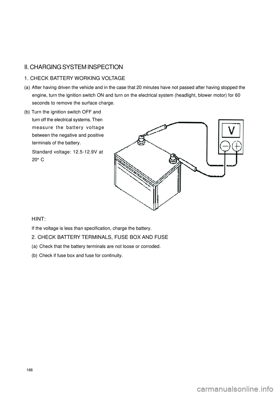
166II. CHARGING SYSTEM INSPECTION1. CHECK BATTERY WORKING VOLTAGE
(a) After having driven the vehicle and in the case that 20 minutes have not passed after having stopped the
engine, turn the ignition switch ON and turn on the electrical system (headlight, blower motor) for 60
seconds to remove the surface charge.
(b) Turn the ignition switch OFF and
turn off the electrical systems. Then
measure the battery voltage
between the negative and positive
terminals of the battery.
Standard voltage: 12.5-12.9V at
20°C
HINT:
If the voltage is less than specification, charge the battery.
2. CHECK BATTERY TERMINALS, FUSE BOX AND FUSE
(a) Check that the battery terminals are not loose or corroded.
(b) Check if fuse box and fuse for continuity.
Page 182 of 392
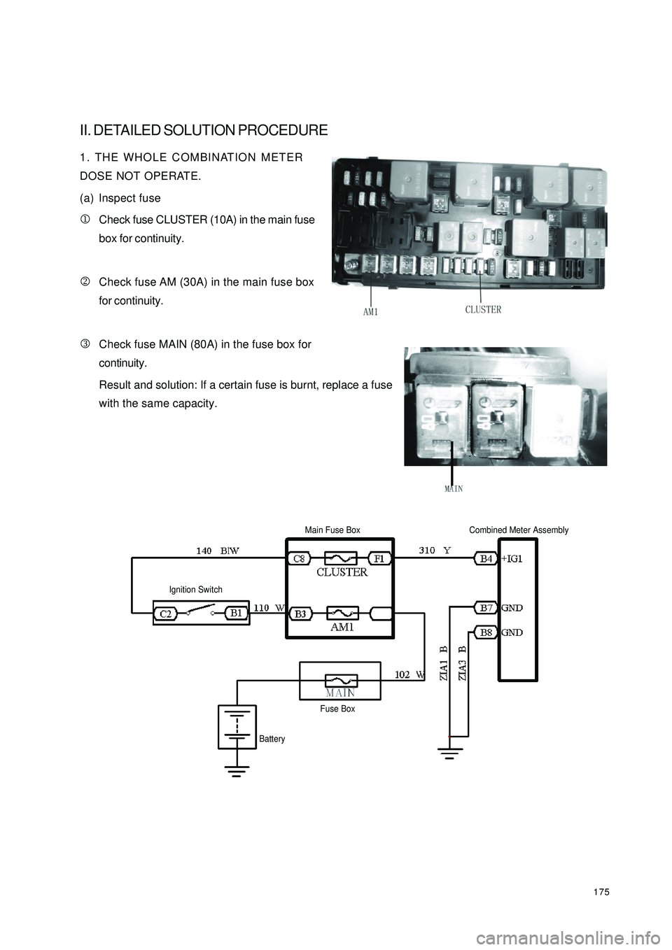
175II. DETAILED SOLUTION PROCEDURE1. THE WHOLE COMBINATION METER
DOSE NOT OPERATE.
(a) Inspect fuse
1Check fuse CLUSTER (10A) in the main fuse
box for continuity.
2Check fuse AM (30A) in the main fuse box
for continuity.
3Check fuse MAIN (80A) in the fuse box for
continuity.
Result and solution: If a certain fuse is burnt, replace a fuse
with the same capacity.Ignition SwitchMain Fuse BoxCombined Meter AssemblyBatteryFuse Box
Page 200 of 392
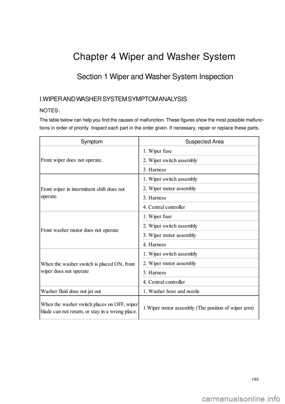
193Chapter 4 Wiper and Washer SystemSection 1 Wiper and Washer System InspectionI.WIPER AND WASHER SYSTEM SYMPTOM ANALYSISNOTES:
The table below can help you find the causes of malfunction. These figures show the most possible malfunc-
tions in order of priority. Inspect each part in the order given. If necessary, repair or replace these parts.Symptom Suspected Area
1. Wipe r fuse
2. Wipe r switc h a sse mbly
3. Harne ss
1. Wipe r switc h a sse mbly
2. Wipe r motor a sse mbly
3. Harne ss
4. Ce ntra l controlle r
1. Wipe r fuse
2. Wipe r switc h a sse mbly
3. Wipe r motor a sse mbly
4. Harne ss
1. Wipe r switc h a sse mbly
2. Wipe r motor a sse mbly
3. Harne ss
4. Ce ntra l controlle r
Wa she r fluid dose not jet out 1. Wa she r hose a nd nozzleWhen the washer switch places on OFF, wiperbla de ca n not return, or sta y in a wrong pla ce .1.Wipe r motor a sse mbly (The position of wipe r a rm) Front wipe r doe s not operate .
Front wipe r in inte rmitte nt shift does not
operate.
Front wa she r motor doe s not operate
When the washer switch is placed ON, front
wipe r does not ope ra te
Page 207 of 392
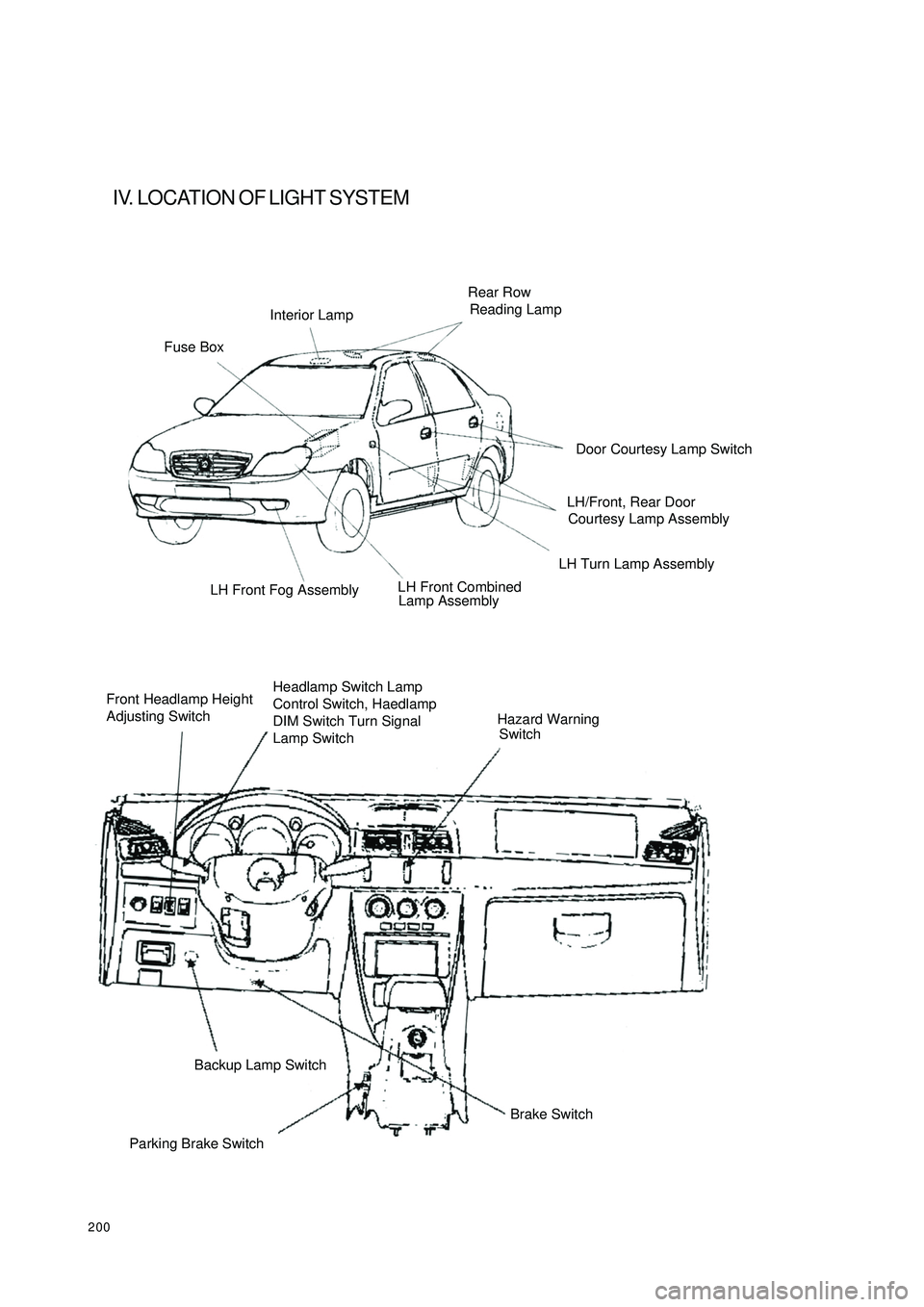
200IV. LOCATION OF LIGHT SYSTEMFuse BoxInterior LampRear Row
Reading LampLH Turn Lamp Assembly
Lamp Assembly LH Front Fog Assembly
Front Headlamp Height
Adjusting SwitchHeadlamp Switch Lamp
Control Switch, Haedlamp
DIM Switch Turn Signal
Lamp SwitchHazard Warning
SwitchParking Brake SwitchBackup Lamp Switch
Brake SwitchDoor Courtesy Lamp Switch
LH/Front, Rear Door
Courtesy Lamp Assembly
LH Front Combined
Page 209 of 392
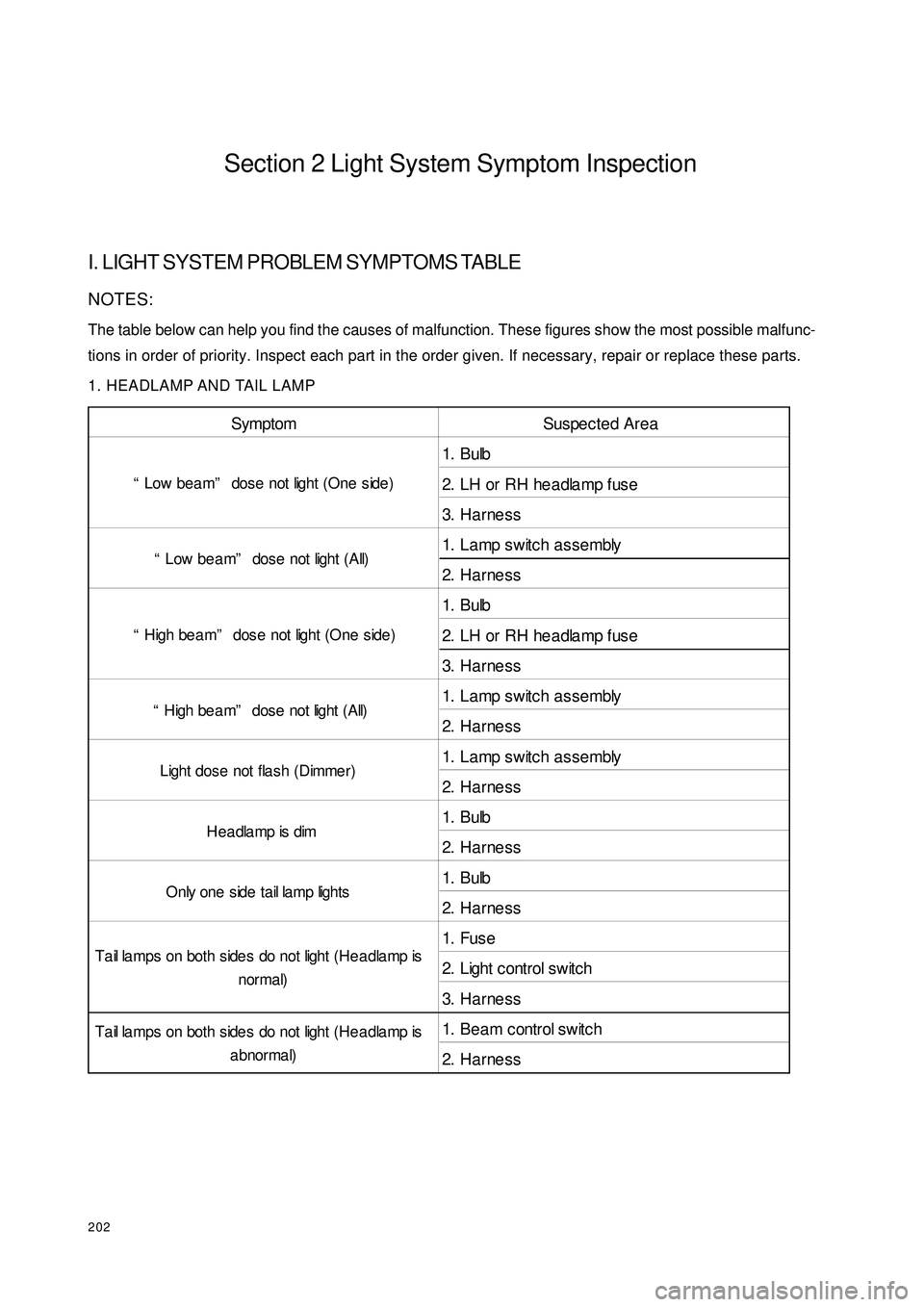
202Section 2 Light System Symptom InspectionI. LIGHT SYSTEM PROBLEM SYMPTOMS TABLENOTES:
The table below can help you find the causes of malfunction. These figures show the most possible malfunc-
tions in order of priority. Inspect each part in the order given. If necessary, repair or replace these parts.
1. HEADLAMP AND TAIL LAMPSymptom Suspec te d Area
1. Bulb
2. LH or RH headlamp fuse
3. H a rne ss
1. Lamp switch assembly
2. H a rne ss
1. Bulb
2. LH or RH headlamp fuse
3. H a rne ss
1. Lamp switch assembly
2. H a rne ss
1. Lamp switch assembly
2. H a rne ss
1. Bulb
2. H a rne ss
1. Bulb
2. H a rne ss
1. Fus e
2. Light c ontrol switc h
3. H a rne ss
1. Be a m c ontrol s witc h
2. H a rne ss “Low bea m” dose not light (One side )
“Low be a m” dose not light (All)
“High be am” dose not light (One side )
“H igh be a m” dos e not light ( A ll)
Ta il lamps on both side s do not light (He a dla mp is
a bnorma l) Light dose not fla sh (Dimme r)
H e a dla mp is dim
O nly one s ide t a il la mp light s
Ta il lamps on both side s do not light (He a dla mp is
normal)
Page 210 of 392
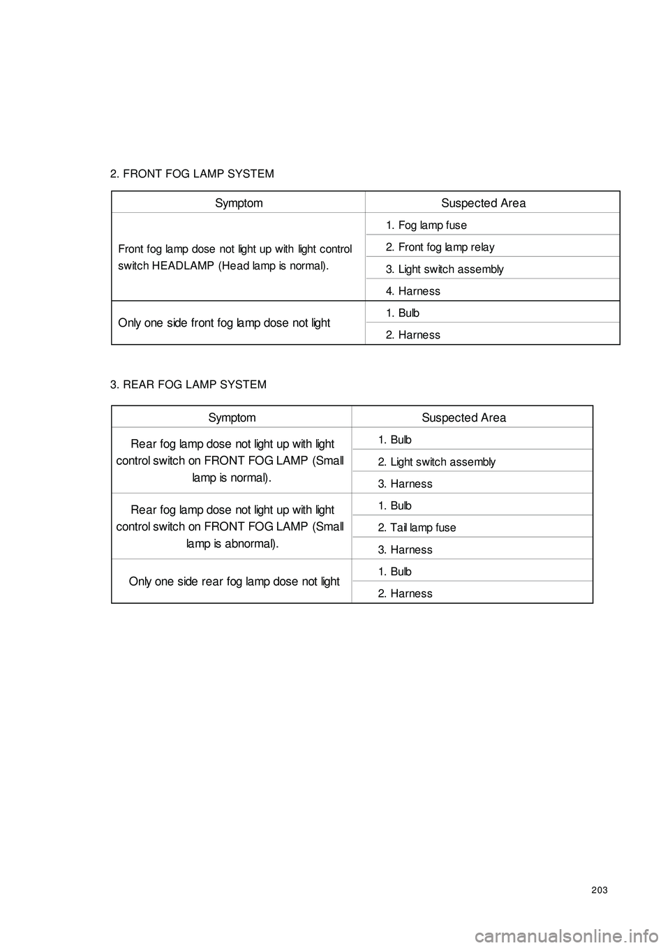
2032. FRONT FOG LAMP SYSTEM
3. REAR FOG LAMP SYSTEMSymptom Suspected Area
1. Fog la mp fuse
2. Front fog la mp rela y
3. Light switc h a ssembly
4. Harne ss
1. Bulb
2. Harne ss Front fog lamp dose not light up with light c ontrol
switch HEADLAMP (Head lamp is normal).
Only one side front fog la mp dose not lightSymptom Suspected Area
1. Bulb
2. Light switc h a ssembly
3. Harne ss
1. Bulb
2. T a il la mp f us e
3. Harne ss
1. Bulb
2. Harne ss Re a r fog lamp dose not light up with light
control switch on FRONT FOG LAMP (Small
la mp is nor ma l) .
Re a r fog lamp dose not light up with light
control switch on FRONT FOG LAMP (Small
la mp is abnormal).
Only one side rea r fog la mp dose not light