check engine GEELY FC 2008 Workshop Manual
[x] Cancel search | Manufacturer: GEELY, Model Year: 2008, Model line: FC, Model: GEELY FC 2008Pages: 419, PDF Size: 13.87 MB
Page 17 of 419
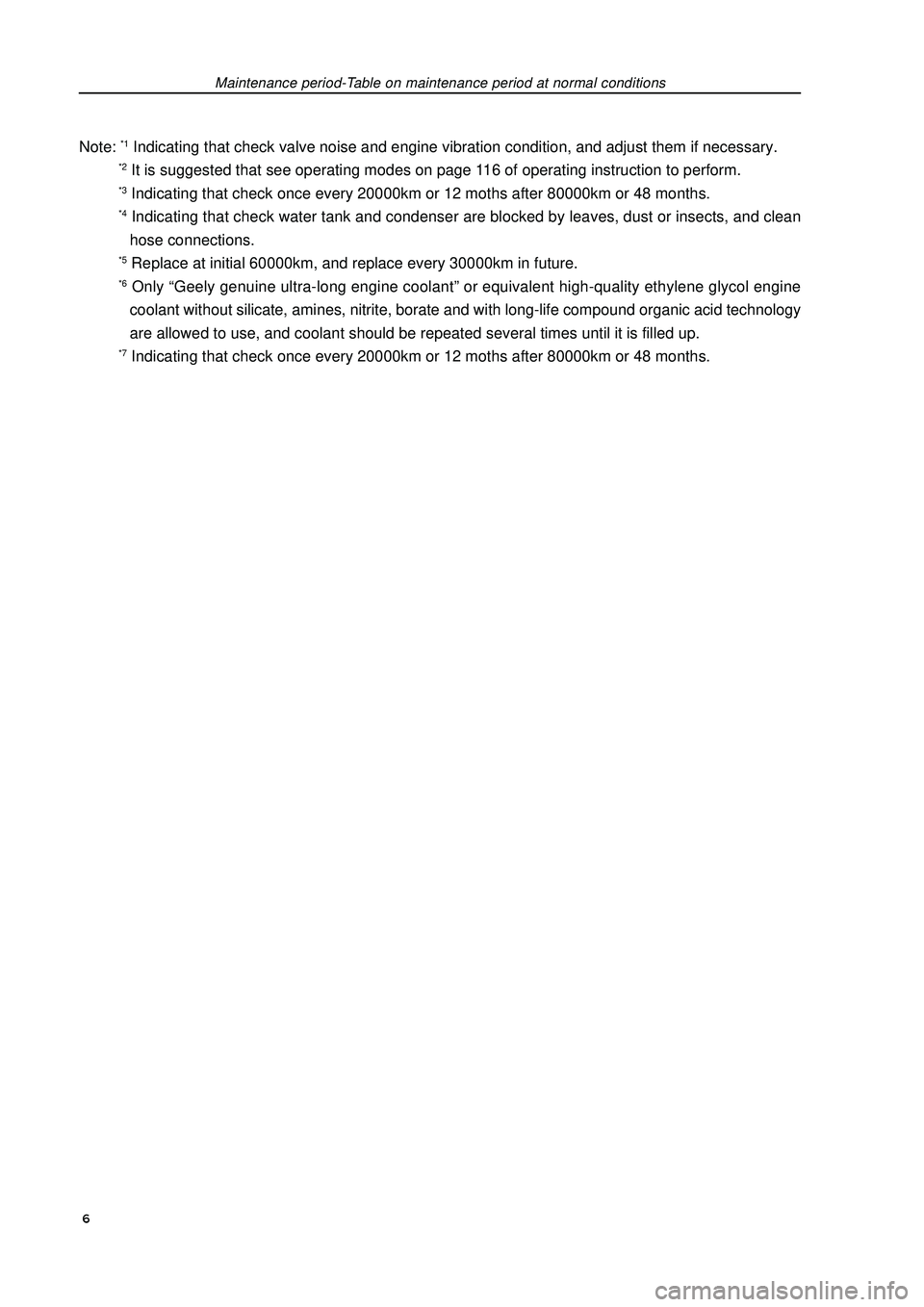
Note: *1 Indicating that check valve noise and engine vibration condition, and adjust them if necessary.*2 It is suggested that see operating modes on page 116 of operating instruction to perform.*3 Indicating that check once every 20000km or 12 moths after 80000km or 48 months.*4 Indicating that check water tank and condenser are blocked by leaves, dust or insects, and clean
hose connections.*5 Replace at initial 60000km, and replace every 30000km in future.*6 Only “Geely genuine ultra-long engine coolant” or equivalent high-quality ethylene glycol engine
coolant without silicate, amines, nitrite, borate and with long-life compound organic acid technology
are allowed to use, and coolant should be repeated several times until it is filled up.*7 Indicating that check once every 20000km or 12 moths after 80000km or 48 months.Maintenance period-Table on maintenance period at normal conditions 6
Page 18 of 419
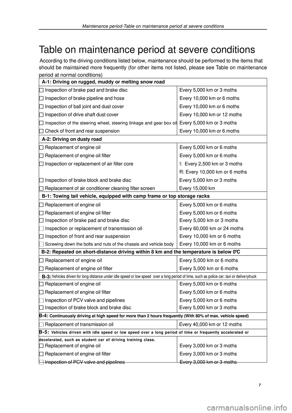
Maintenance period-Table on maintenance period at severe conditionsTable on maintenance period at severe conditionsAccording to the driving conditions listed below, maintenance should be performed to the items that
should be maintained more frequently (for other items not listed, please see Table on maintenance
period at normal conditions) 7 A-1: Driving on rugged, muddy or melting snow road Inspection of brake pad and brake disc Every 5,000 km or 3 moths Inspection of brake pipeline and hose Every 10,000 km or 6 moths Inspection of ball joint and dust cover Every 10,000 km or 6 moths Inspection of drive shaft dust cover Every 10,000 km or 12 moths Inspection of the steering wheel, steering linkage and gear box oilEvery 5,000 km or 3 moths Check of front and rear suspension Every 10,000 km or 6 moths
A-2: Driving on dusty road Replacement of engine oil Every 5,000 km or 6 moths Replacement of engine oil filter Every 5,000 km or 6 moths Inspection or replacement of air filter core I: Every 2,500 km or 3 moths
R: Every 10,000 km or 6 moths Inspection of brake block and brake disc Every 5,000 km or 3 moths Replacement of air conditioner cleaning filter screen Every 15,000 km
B-1: Towing tail vehicle, equipped with camp frame or top storage racks Replacement of engine oil Every 5,000 km or 6 moths Replacement of engine oil filter Every 5,000 km or 6 moths Inspection of brake pad and brake disc Every 5,000 km or 3 moths Inspection or replacement of transmission oil Every 60,000 km or 24 moths Inspection of front and rear suspension Every 10,000 km or 6 moths Screwing down the bolts and nuts of the chassis and vehicle bodyEvery 10,000 km or 6 moths
B-2: Repeated on short-distance driving within 8 km and the temperature is below 0 °C Replacement of engine oil Every 5,000 km or 6 moths Replacement of engine oil filter Every 5,000 km or 6 moths
B-3: Vehicles driven for long distance under idle speed or low speed over a long period of time, such as police car, taxi or deliverytruck. Replacement of engine oil Every 5,000 km or 6 moths Replacement of engine oil filter Every 5,000 km or 6 moths Inspection of PCV valve and pipelines Every 5,000 km or 6 moths Inspection of brake block and brake disc Every 5,000 km or 3 moths
B-4: Continuously driving at high speed for more than 2 hours frequently (With 80% of max. vehicle speed) Replacement of transmission oil Every 40,000 km or 12 moths
B-5: Vehicles driven with idle speed or low speed over a long period of time or frequently accelerated or
decelerated, such as student car of driving training class. Replacement of engine oil Every 3,000 km or 3 moths Replacement of engine oil filter Every 3,000 km or 3 moths Inspection of PCV valve and pipelines Every 3,000 km or 3 moths
Page 19 of 419
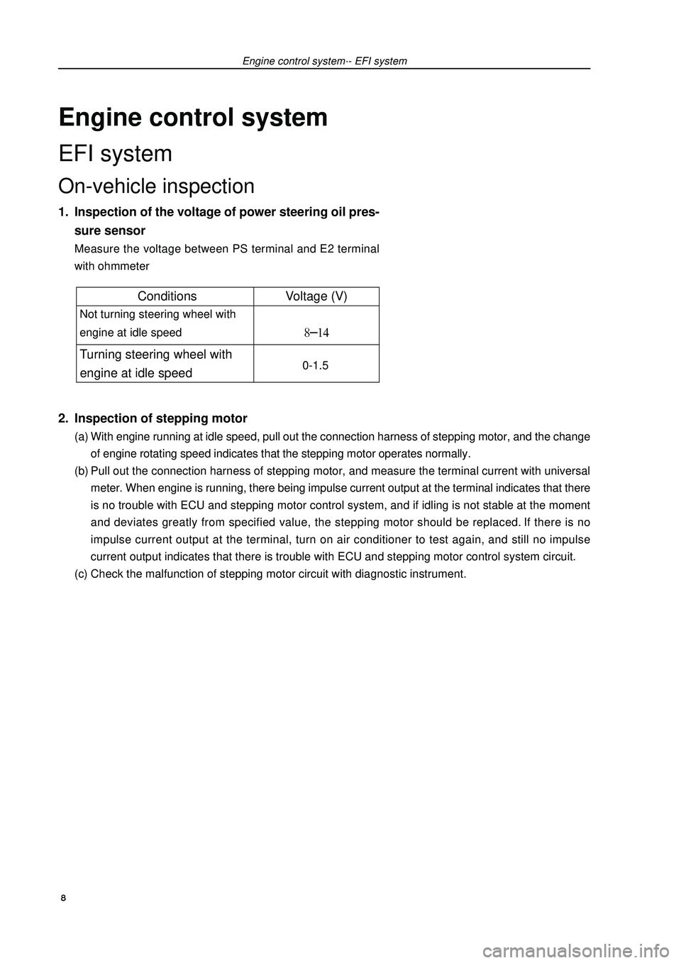
Engine control systemEFI systemOn-vehicle inspection1. Inspection of the voltage of power steering oil pres-
sure sensorMeasure the voltage between PS terminal and E2 terminal
with ohmmeter2. Inspection of stepping motor(a) With engine running at idle speed, pull out the connection harness of stepping motor, and the change
of engine rotating speed indicates that the stepping motor operates normally.
(b) Pull out the connection harness of stepping motor, and measure the terminal current with universal
meter. When engine is running, there being impulse current output at the terminal indicates that there
is no trouble with ECU and stepping motor control system, and if idling is not stable at the moment
and deviates greatly from specified value, the stepping motor should be replaced. If there is no
impulse current output at the terminal, turn on air conditioner to test again, and still no impulse
current output indicates that there is trouble with ECU and stepping motor control system circuit.
(c) Check the malfunction of stepping motor circuit with diagnostic instrument.Engine control system·- EFI system 8Conditions Voltage (V) Not turning steering wheel with
engine at idle speed Turning steering wheel with
engine at idle speed 0-1.5
Page 20 of 419
Engine control system·- EFI systemInspection1. VVT control solenoid valve assembly (4G18-1006200)(a) Resistance inspection
(1) Measure the resistance between terminals with ohmmeter
Resistance: (b) Operation inspection
Connect battery positive (+) wire to No.1 terminal and negative (-) wire to No. 2 terminal, and check
valve operation.
Note: ensure that the valve is not stuck.
Hint: if there are foreign matters in the valve, the valve could not be closed tightly and will
thus result in slight pressure being lifted toward higher direction.2. Throttle body components (4G18-1001240)(a) Inspection of throttle body
(1) Throttle valve shaft should not swing.
(2) All channels should not be blocked.
(3) Throttle valve plate should rotate flexibly and act smoothly.
(4) When the throttle is at closed position, there should be no clearance between throttle stop bolts and
throttle lever.
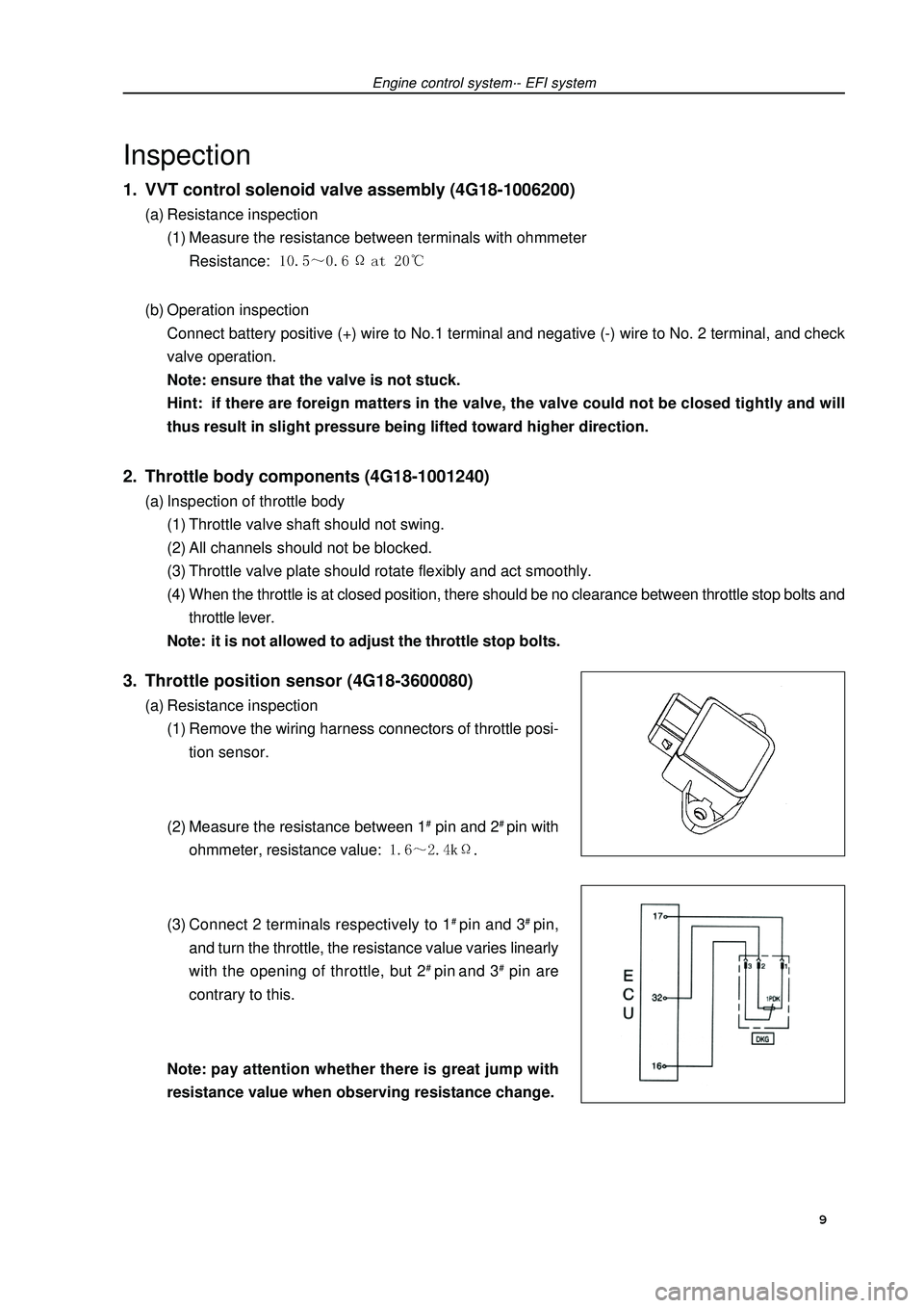
Note: it is not allowed to adjust the throttle stop bolts.3. Throttle position sensor (4G18-3600080)(a) Resistance inspection
(1) Remove the wiring harness connectors of throttle posi-
tion sensor.
(2) Measure the resistance between 1# pin and 2# pin with
ohmmeter, resistance value: .
(3) Connect 2 terminals respectively to 1# pin and 3# pin,
and turn the throttle, the resistance value varies linearly
with the opening of throttle, but 2# pin and 3# pin are
contrary to this.
Note:pay attention whether there is great jump with
resistance value when observing resistance change. 9
Page 24 of 419
Engine control system·- Throttle body assemblyThrottle body assemblyRemoving, installing and disassembling, assembling1. Discharge coolant (see Page 73).
2. Remove air cleaner hose assembly.
3. Remove engine plastic hood components [4G18-1000310].
4. Remove throttle pull cable assembly.
5. remove throttle body assembly [4G18-1008240].(a) Uncouple throttle position sensor joint and stepping motor joint.
(b) Disassemble ventilation hose.
(c) Remove 2 bolts and throttle control pull cable bracket.
(d) Remove 2 preheating water inlet and outlet hoses of throttle.
(e) Remove 2 bolts and 2 nuts, and remove throttle body from intake air manifold.6. Remove stepping motor of throttle body [4G18-3600070].Remove 3 screws and stepping motor.7. Install stepping motor of throttle body.Install stepping motor.8. Install throttle body assembly.(a) Install new seal gasket on intake air manifold.
(b) Install throttle body, 2 bolts and 2 nuts.
Torque: 9. Refill coolant.
10.Check there is leakage with coolant.
13
Page 26 of 419
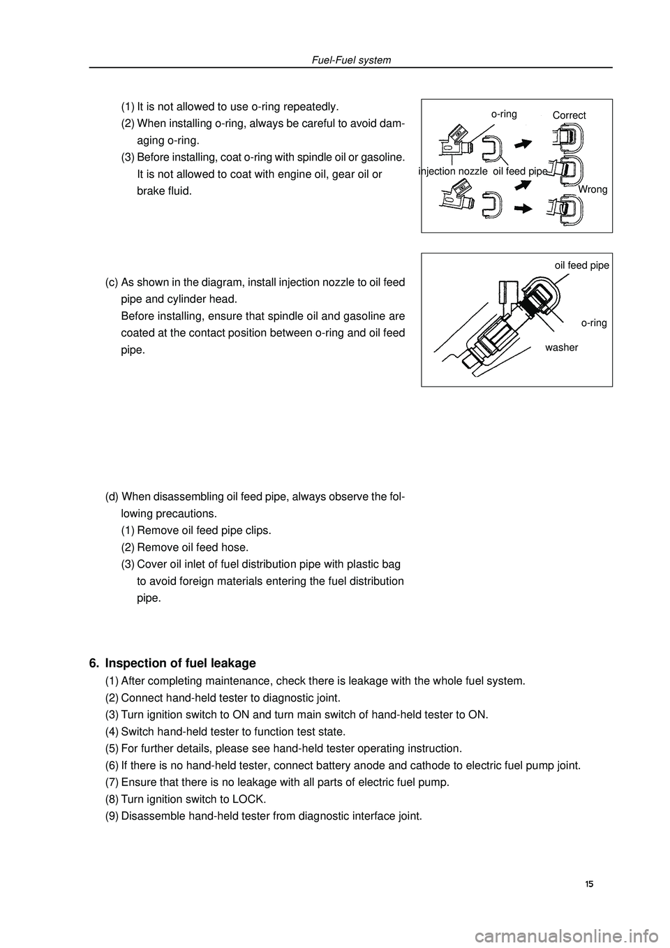
Fuel-Fuel system(1) It is not allowed to use o-ring repeatedly.
(2) When installing o-ring, always be careful to avoid dam-
aging o-ring.
(3) Before installing, coat o-ring with spindle oil or gasoline.
It is not allowed to coat with engine oil, gear oil or
brake fluid.
(c) As shown in the diagram, install injection nozzle to oil feed
pipe and cylinder head.
Before installing, ensure that spindle oil and gasoline are
coated at the contact position between o-ring and oil feed
pipe.
(d) When disassembling oil feed pipe, always observe the fol-
lowing precautions.
(1) Remove oil feed pipe clips.
(2) Remove oil feed hose.
(3) Cover oil inlet of fuel distribution pipe with plastic bag
to avoid foreign materials entering the fuel distribution
pipe.injection nozzle6. Inspection of fuel leakage(1) After completing maintenance, check there is leakage with the whole fuel system.
(2) Connect hand-held tester to diagnostic joint.
(3) Turn ignition switch to ON and turn main switch of hand-held tester to ON.
(4) Switch hand-held tester to function test state.
(5) For further details, please see hand-held tester operating instruction.
(6) If there is no hand-held tester, connect battery anode and cathode to electric fuel pump joint.
(7) Ensure that there is no leakage with all parts of electric fuel pump.
(8) Turn ignition switch to LOCK.
(9) Disassemble hand-held tester from diagnostic interface joint.15o-ringoil feed pipeoil feed pipeo-ringwasherCorrect
Wrong
Page 27 of 419
On-vehicle inspection1. Inspection of fuel pump function(a) Connect hand-held tester to diagnostic joint.
(b) Turn ignition switch to ON and turn main switch of hand-
held tester to ON.
Note: do not start the engine.
(c) Switch hand-held tester to function test state.
(d) For further details, please see hand-held tester operating
instruction.
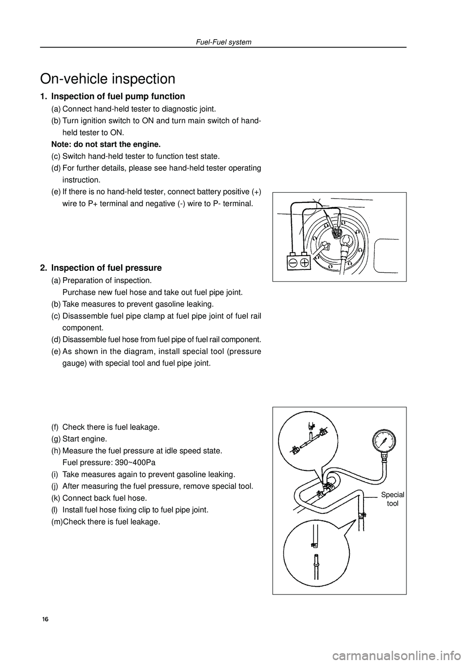
(e) If there is no hand-held tester, connect battery positive (+)
wire to P+ terminal and negative (-) wire to P- terminal.2. Inspection of fuel pressure(a) Preparation of inspection.
Purchase new fuel hose and take out fuel pipe joint.
(b) Take measures to prevent gasoline leaking.
(c) Disassemble fuel pipe clamp at fuel pipe joint of fuel rail
component.
(d) Disassemble fuel hose from fuel pipe of fuel rail component.
(e) As shown in the diagram, install special tool (pressure
gauge) with special tool and fuel pipe joint.
(f) Check there is fuel leakage.
(g) Start engine.
(h) Measure the fuel pressure at idle speed state.
Fuel pressure: 390~400Pa
(i) Take measures again to prevent gasoline leaking.
(j) After measuring the fuel pressure, remove special tool.
(k) Connect back fuel hose.
(l) Install fuel hose fixing clip to fuel pipe joint.
(m)Check there is fuel leakage.Fuel-Fuel systemSpecial
tool 16
Page 28 of 419
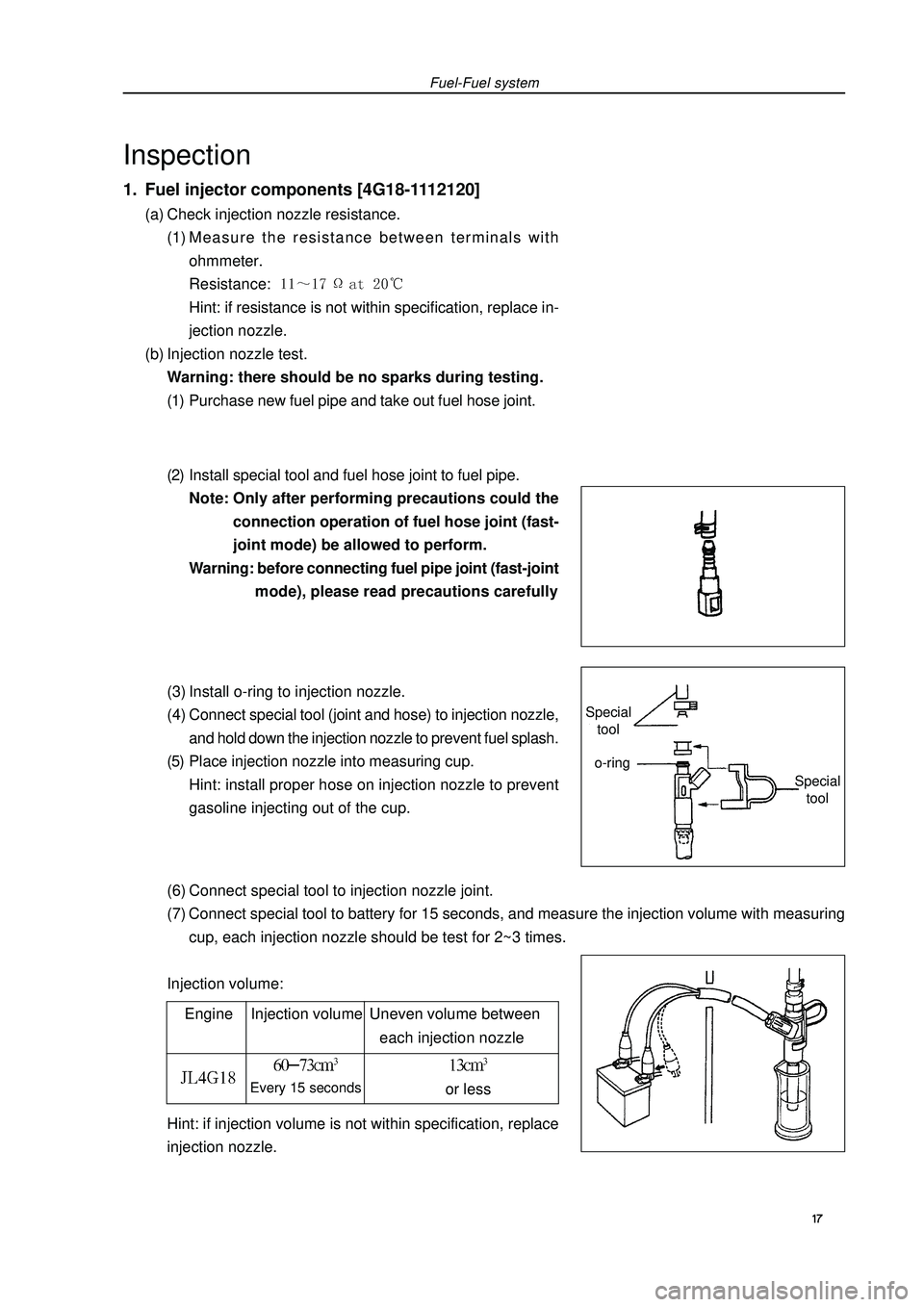
(6) Connect special tool to injection nozzle joint.
(7) Connect special tool to battery for 15 seconds, and measure the injection volume with measuring
cup, each injection nozzle should be test for 2~3 times.
Injection volume:Fuel-Fuel systemInspection1. Fuel injector components [4G18-1112120](a) Check injection nozzle resistance.
(1) Measure the resistance between terminals with
ohmmeter.
Resistance: Hint: if resistance is not within specification, replace in-
jection nozzle.
(b) Injection nozzle test.
Warning: there should be no sparks during testing.
(1) Purchase new fuel pipe and take out fuel hose joint.
(2) Install special tool and fuel hose joint to fuel pipe.
Note: Only after performing precautions could the
connection operation of fuel hose joint (fast-
joint mode) be allowed to perform.
Warning: before connecting fuel pipe joint (fast-joint
mode), please read precautions carefully
(3) Install o-ring to injection nozzle.
(4) Connect special tool (joint and hose) to injection nozzle,
and hold down the injection nozzle to prevent fuel splash.
(5) Place injection nozzle into measuring cup.
Hint: install proper hose on injection nozzle to prevent
gasoline injecting out of the cup.
Engine Injection volume Uneven volume between
each injection nozzleEvery 15 secondsor lessHint: if injection volume is not within specification, replace
injection nozzle. 17 Special
toolSpecial
toolo-ring
Page 29 of 419
![GEELY FC 2008 Workshop Manual Fuel-Injection nozzle assemblyInjection nozzle assemblyReplacement1. Take measures to prevent gasoline leaking.
2. Remove engine plastic hood components.
3. Uncouple engine wire harness [4G18-3724100] GEELY FC 2008 Workshop Manual Fuel-Injection nozzle assemblyInjection nozzle assemblyReplacement1. Take measures to prevent gasoline leaking.
2. Remove engine plastic hood components.
3. Uncouple engine wire harness [4G18-3724100]](/img/58/57161/w960_57161-28.png)
Fuel-Injection nozzle assemblyInjection nozzle assemblyReplacement1. Take measures to prevent gasoline leaking.
2. Remove engine plastic hood components.
3. Uncouple engine wire harness [4G18-3724100].(a) Remove injection nozzle joint.
(b) Remove exhaust gas hose.4. Remove fuel pipe assembly(a) Loosen oil feed hose clips.
(b) Pull oil feed hose away from fuse distribution pipe.
Notes:�zCheck there is dirt on fuel pipe and its joint before removing, and clean it off in the case of dirt.�zIt is only allowed to remove with hands.�zCheck there are foreign matters with the removed fuel pipe seal surface, and clean them off in the
case of foreign matters.�zCover the fuel pipe with plastic bag to avoid pipe damage and foreign matters entering.5. Remove fuel pipe assemblyRemove 2 bolts and oil feed pipe (together with injection nozzle).6. Remove injection nozzle components.Pull out 4 injection nozzles from oil feed pipe.7. Install injection nozzle components.Coat a thin layer of gasoline on o-ring and rotate left and right to push injection nozzle into oil feed pipe.
Notes:
�zBe careful not to rotate o-ring.
�zCheck injection nozzle could rotate smoothly after it is installed, and if not replace with new o-ring.8. Install fuel hose assembly.Install fuel hose to oil feed pipe.
Notes:
�zCheck there are damage or foreign matters in the binding site of fuel pipe.
�zAfter installing, pull the fuel pump with hands to check the fuel pipe is bound firmly with joint. 18
Page 34 of 419
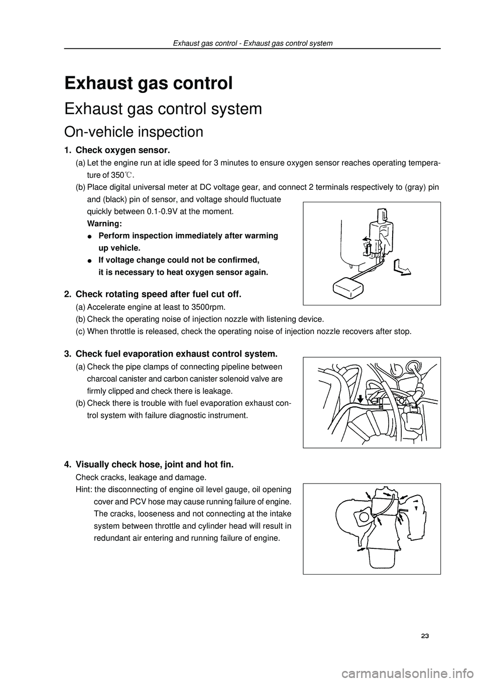
Exhaust gas controlExhaust gas control systemOn-vehicle inspection1. Check oxygen sensor.(a) Let the engine run at idle speed for 3 minutes to ensure oxygen sensor reaches operating tempera-
ture of 350(b) Place digital universal meter at DC voltage gear, and connect 2 terminals respectively to (gray) pin
and (black) pin of sensor, and voltage should fluctuate
quickly between 0.1-0.9V at the moment.
Warning:Perform inspection immediately after warming
up vehicle.If voltage change could not be confirmed,
it is necessary to heat oxygen sensor again.Exhaust gas control - Exhaust gas control system2. Check rotating speed after fuel cut off.(a) Accelerate engine at least to 3500rpm.
(b) Check the operating noise of injection nozzle with listening device.
(c) When throttle is released, check the operating noise of injection nozzle recovers after stop.3. Check fuel evaporation exhaust control system.(a) Check the pipe clamps of connecting pipeline between
charcoal canister and carbon canister solenoid valve are
firmly clipped and check there is leakage.
(b) Check there is trouble with fuel evaporation exhaust con-
trol system with failure diagnostic instrument.4. Visually check hose, joint and hot fin.Check cracks, leakage and damage.
Hint: the disconnecting of engine oil level gauge, oil opening
cover and PCV hose may cause running failure of engine.
The cracks, looseness and not connecting at the intake
system between throttle and cylinder head will result in
redundant air entering and running failure of engine.23