clock GEELY FC 2008 Workshop Manual
[x] Cancel search | Manufacturer: GEELY, Model Year: 2008, Model line: FC, Model: GEELY FC 2008Pages: 419, PDF Size: 13.87 MB
Page 40 of 419

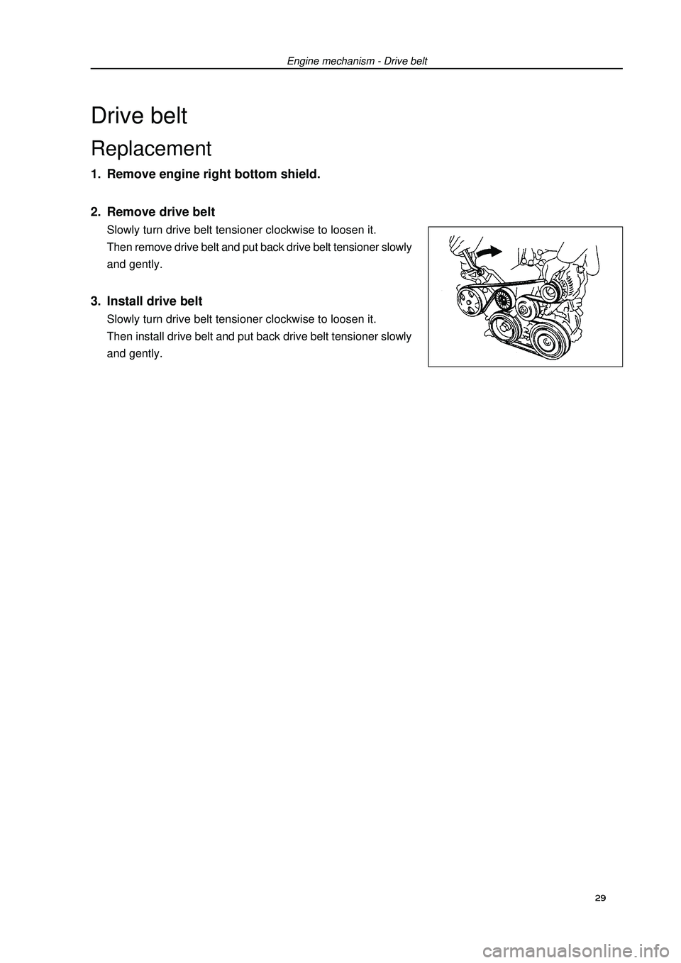
Engine mechanism - Drive beltDrive beltReplacement1. Remove engine right bottom shield.
2. Remove drive beltSlowly turn drive belt tensioner clockwise to loosen it.
Then remove drive belt and put back drive belt tensioner slowly
and gently.3. Install drive beltSlowly turn drive belt tensioner clockwise to loosen it.
Then install drive belt and put back drive belt tensioner slowly
and gently.29
Page 41 of 419
![GEELY FC 2008 Workshop Manual Engine mechanism - Valve clearanceValve clearanceAdjustment1. Remove engine plastic hood components.
2. Remove ignition coil components [4G18-3705110].
3. Remove cylinder head cover components [4G18-
GEELY FC 2008 Workshop Manual Engine mechanism - Valve clearanceValve clearanceAdjustment1. Remove engine plastic hood components.
2. Remove ignition coil components [4G18-3705110].
3. Remove cylinder head cover components [4G18-](/img/58/57161/w960_57161-40.png)
Engine mechanism - Valve clearanceValve clearanceAdjustment1. Remove engine plastic hood components.
2. Remove ignition coil components [4G18-3705110].
3. Remove cylinder head cover components [4G18-
1003130].
4. Remove engine right bottom shield.
5. Turn crankshaft to cylinder 1 compression top dead
center position.(a) Turn crankshaft pulley to align its groove with “o” mark on
timing chain hood.
(b) Check dot marks on camshaft timing sprocket and VVT
timing sprocket, and they should be in a line on timing chain
hood surface as shown in the diagram.
Hint: if not, turn crankshaft for one circle again
and align the above marks.6. Check valve clearance.(a) Only check the valves shown in the diagram.
(1) Measure the clearance between valve tappet and cam-
shaft with plug gauge.
(2) Record valve clearance measuring value exceeding
specification, and this value will be used to determine
valve tappet thickness that needs change.
Valve clearance (cold vehicle)Intake airExhaust(b) Turn crankshaft for one circle ), and cylinder 4 is
turned to compression top dead center position.
(c) Only check the valves shown in the diagram. Measure valve
clearance (see step (a)).7. Remove drive beltSlowly turn drive belt tensioner clockwise to loosen it.
Then remove drive belt and put back drive belt tensioner slowly
and gently. 30 Mark
Mark
Mark
Timing chain
hood surface
Groove
Page 45 of 419

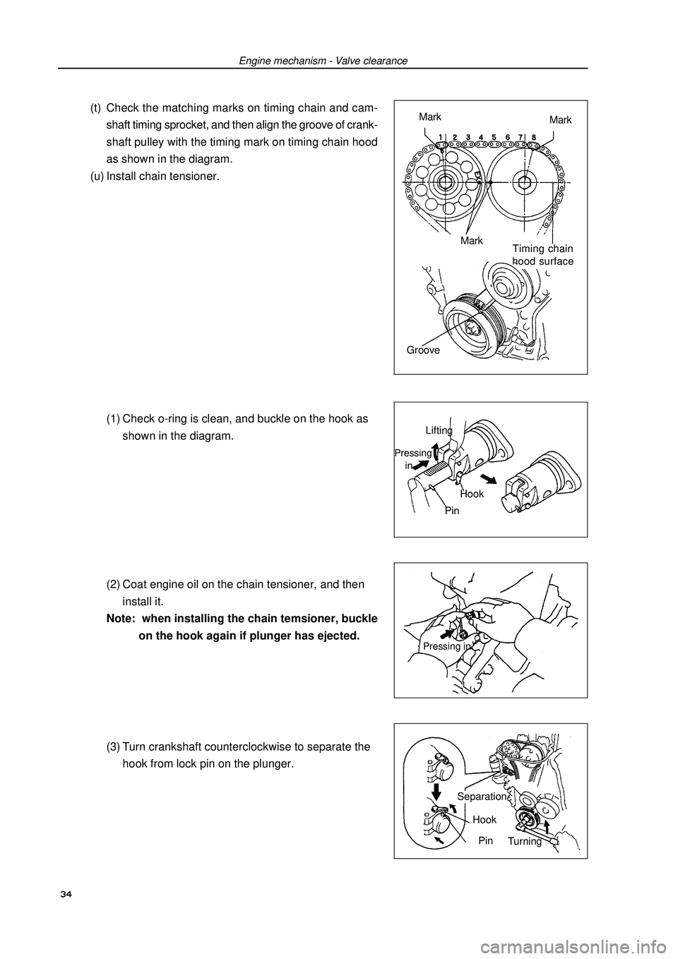
Engine mechanism - Valve clearance(t) Check the matching marks on timing chain and cam-
shaft timing sprocket, and then align the groove of crank-
shaft pulley with the timing mark on timing chain hood
as shown in the diagram.
(u) Install chain tensioner.
(1) Check o-ring is clean, and buckle on the hook as
shown in the diagram.
(2) Coat engine oil on the chain tensioner, and then
install it.
Note: when installing the chain temsioner, buckle
on the hook again if plunger has ejected.
(3) Turn crankshaft counterclockwise to separate the
hook from lock pin on the plunger.Mark
Mark
Mark
Timing chain
hood surface
GroovePressing in 34 Lifting
HookPressing
inPinTurning Pin Separation
Hook
Page 46 of 419

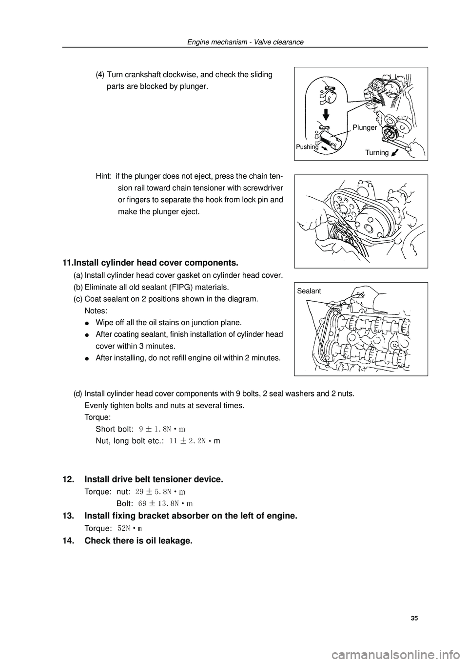
Engine mechanism - Valve clearance(4) Turn crankshaft clockwise, and check the sliding
parts are blocked by plunger.
Hint: if the plunger does not eject, press the chain ten-
sion rail toward chain tensioner with screwdriver
or fingers to separate the hook from lock pin and
make the plunger eject.11.Install cylinder head cover components.(a) Install cylinder head cover gasket on cylinder head cover.
(b) Eliminate all old sealant (FIPG) materials.
(c) Coat sealant on 2 positions shown in the diagram.
Notes:Wipe off all the oil stains on junction plane.After coating sealant, finish installation of cylinder head
cover within 3 minutes.After installing, do not refill engine oil within 2 minutes.
(d) Install cylinder head cover components with 9 bolts, 2 seal washers and 2 nuts.
Evenly tighten bolts and nuts at several times.
Torque:
Short bolt: Nut, long bolt etc.: m12. Install drive belt tensioner device.Torque: nut: Bolt: 13. Install fixing bracket absorber on the left of engine.Torque: 14. Check there is oil leakage.Sealant 35 Plunger
TurningPushing
Page 48 of 419
![GEELY FC 2008 Workshop Manual Engine mechanism - Engine assembly22. Remove drive belt.Drive belt tensioner could turn belt tensioner clockwise to
loosen it.23. Remove alternator mounting components [4G18-
3701100].
24. Remove comp GEELY FC 2008 Workshop Manual Engine mechanism - Engine assembly22. Remove drive belt.Drive belt tensioner could turn belt tensioner clockwise to
loosen it.23. Remove alternator mounting components [4G18-
3701100].
24. Remove comp](/img/58/57161/w960_57161-47.png)
Engine mechanism - Engine assembly22. Remove drive belt.Drive belt tensioner could turn belt tensioner clockwise to
loosen it.23. Remove alternator mounting components [4G18-
3701100].
24. Remove compressor assembly.
25. Remove front chassis bracket.
26. Remove front exhaust pipe assembly.
27. Remove steering middle shaft assembly.(a) Remove steering column seal hole cover.
(b) Make alignment mark on steering middle shaft.
(c) Remove 2 bolts and steering middle shaft.
(d) Remove steering column cover.28. Remove the nuts on left side of front shaft hub.(a) Completely knock out the concave part of fixed nuts with
special tool and hammer.
Notes:Completely knock out the concave part of fixed
nuts before removing the fixed nuts.Do not damage thread of drive shaft.Do not sharpen the sharp end of special tool.Place the special tool in groove with its plane facing
upward.
(b) Remove fixed nuts with socket wrench (30mm).
Hint: perform the same steps at another side.29. Disassemble left side transversal lever assembly.Disassemble transversal lever assembly from steering
knuckle with special tool.
Hint: perform the same steps at another side.Alignment
markSpecial tool
Special tool37Sliding outLifting
Page 60 of 419

Engine mechanism - Timing chain assembly(b) Coat engine oil on the chain tensioner, and then install
it.
Torque: Note: when installing the chain temsioner, buckle
on the hook again if plunger has ejected.33. Install damping pulley.(a) Align the key groove on the damping pulley with the
key on the crankshaft, and slide damping pulley in.
(b) Install damping pulley bolts with special tool.
Torque: (c) Turn crankshaft counterclockwise to separate the hook
from lock pin on the plunger.
(d) Turn crankshaft clockwise, and check the chain ten-
sion rail is blocked by plunger.
Hint: if the plunger does not eject, press the chain ten-
sion rail toward chain tensioner with screwdriver
or fingers to separate the hook from lock pin and
make the plunger eject.Special
tool 49 Pushing intoSeparationHook
Pin
TurningPlunger
Pushing
intoTurning
Page 63 of 419

Engine mechanism - CamshaftCamshaftReplacement1. Remove engine hood.
2. Remove ignition coil assembly.
3. Remove cylinder head cover assembly.
4. Remove engine right bottom shield.
5. Turn crankshaft to cylinder 1 compression top dead
center position.(a) Turn damping pulley to align its groove with “o” mark on
timing chain hood.
(b) Check dot marks on camshaft timing sprocket and VVT
timing sprocket, and they should be in a line on timing chain
hood surface as shown in the diagram.
Hint: if not, turn crankshaft for one circle (360) again
and align the above marks.6. Remove drive belt.Slowly turn drive belt tensioner clockwise to loosen it.Then
remove drive belt and put back drive belt tensioner slowly and
gently.7. Remove right engine mounting assembly.(a) Remove PS oil pump reservoir and put it aside.
(b) Place wooden block between jack and engine, properly
place the jack, and then remove engine fixing bracket shock
absorber.8. Remove drive belt tensioner assembly.Hint: operate the jack up and down to remove bolts. 52Mark
Mark
Mark
Timing chain
hood surface
Groove
Page 69 of 419

Engine mechanism - Camshaft(n) Install chain tensioner components.
(1) Check o-ring is clean, and buckle on the hook as
shown in the diagram.
(2) Coat engine oil on the chain tensioner, and then
install it.
Torque: 9 ±1.8N.m
Note:when installing the chain temsioner,
buckle on the hook again if plunger has
ejected.
(3) Turn crankshaft counterclockwise to separate the
hook from lock pin on the plunger.
(4) Turn crankshaft clockwise, and check the sliding
parts are blocked by plunger.
Hint: if the plunger does not eject, press the ten-
sion rail toward chain tensioner with
screwdriver or fingers to separate the hook
from lock pin and make the plunger eject.Pushing into
Turning Plunger
Pushing into58Lifting
Hook Pressing
in
Pin
PinHook Sepa-
rate
Page 71 of 419

Engine mechanism - Crankshaft front oil seal assemblyReplacement1. Remove engine right bottom shield.
2. Remove drive belt.Slowly turn drive belt tensioner clockwise to loosen it. Then
remove drive belt and put back drive belt tensioner slowly and
gently.3. Remove right engine mounting assembly.(a) Remove PS oil pump reservoir and put it aside.
(b) Place wooden block between jack and engine, properly
place the jack, and then remove right engine mounting
assembly.4. remove damping pulley.(a) Remove pulley bolts with special tool.
(b) Remove damping pulley with special tool.Special
tool
Special
tool60Crankshaft front oil seal assembly
Page 80 of 419

Cooling - Water pump assemblyWater pump assemblyReplacement1. Remove engine right bottom shield.
2. Discharge engine coolant.
3. Remove drive belt.Slowly turn drive belt tensioner clockwise to loosen the belt;
then remove drive belt and put back drive belt tensioner slowly
to completely loosen the tensioner.4. Remove alternator assembly.(a) Remove rubber cover and nuts.
(b) Uncouple alternator joint.
(c) Remove 2 bolts and alternator.5. Remove water pump assembly.Remove 6 bolts, water pump and o-ring.69