warning GEELY FC 2008 Workshop Manual
[x] Cancel search | Manufacturer: GEELY, Model Year: 2008, Model line: FC, Model: GEELY FC 2008Pages: 419, PDF Size: 13.87 MB
Page 5 of 419
This manual is mainly for qualified vehicle technicians, but it does not in-
clude all items on repair and maintenance.
In order to avoid personnel injury and vehicle damage caused by dangerous
operation, please observe the following regulations.
�zPlease read this manual carefully, and particularly fully master all con-
tents in “Precautions”.
�zMaintenance methods described in the manual are quite useful for vehicle
maintenance. Please adopt specified or recommended tools in maintain-
ing vehicle as steps described in this manual; maintaining vehicle with
tools or methods not specified or recommended in this manual will cause
personnel injury or vehicle damage. Therefore, please consider ensuring
the safety of technicians and vehicle at first before performing maintenance.
�zIf it is necessary to replace parts, please replace with parts of the same or
similar size with original ones. It is forbidden to use inferior parts.
�zIn order to effectively avoid technician injury and vehicle damage and hid-
den danger caused by incorrect operation, it is very important to observe
“Warning” and “Notes” in this manual. It particularly needs to mention that
not all precautions on safety are included in “Warning” and “Notes” etc. in
this manual. Therefore, please fully realize that perform maintenance not
as regulations will cause dangerous consequences.
Note
Page 11 of 419
Engine cover/automobile door
Engine cover......................................................
366
Adjustment.....................................................
366
Front automobile door........................................
367
Subassembly.................................................
367
Overhaul........................................................
369
Adjustment.....................................................
372
Rear automobile door.......................................
373
Overhaul........................................................
373
Adjustment....................................................
375
Trunk cover.........................................................
377
Adjustment....................................................
377
Torsion spring of trunk cover.............................
378
Change..........................................................
378
Exterior/inner trim board
Front bumper....................................................
379
Subassembly................................................
379
Change..........................................................
380
Rear bumper......................................................
381
Subassembly................................................
381
Change..........................................................
382
Name plate........................................................
383
Change..........................................................
383
Exterior seal tape of left front door glass (LH)...
384
Change..........................................................
384
Exterior seal tape of left rear door glass...........
385
Change..........................................................
385
Light fender........................................................
386
Change..........................................................
386
Top left trim tape.................................................
387
Replacement.................................................
387
Left lower fender of automobile body (LH)........
388
Subassembly................................................
388
Change..........................................................
389
Inner trim board of top........................................
390
Change..........................................................
390Automobile control system
Ignition switch and anti-versa lock key warning switch.394
Malfunction phenomenon table.....................
394
Inspection......................................................
394
Electrical schematic diagram..............................
395
Page 28 of 419
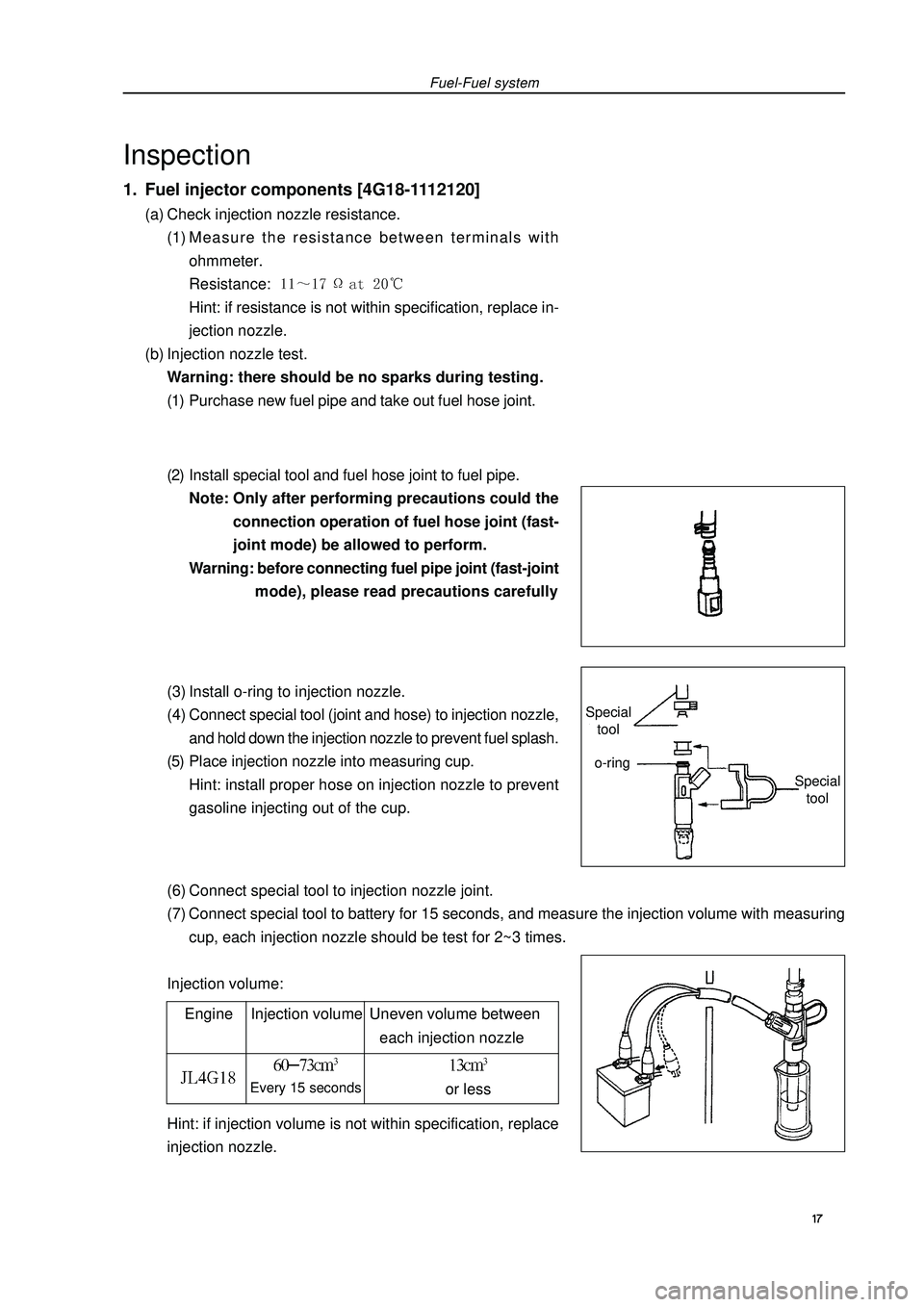
(6) Connect special tool to injection nozzle joint.
(7) Connect special tool to battery for 15 seconds, and measure the injection volume with measuring
cup, each injection nozzle should be test for 2~3 times.
Injection volume:Fuel-Fuel systemInspection1. Fuel injector components [4G18-1112120](a) Check injection nozzle resistance.
(1) Measure the resistance between terminals with
ohmmeter.
Resistance: Hint: if resistance is not within specification, replace in-
jection nozzle.
(b) Injection nozzle test.
Warning: there should be no sparks during testing.
(1) Purchase new fuel pipe and take out fuel hose joint.
(2) Install special tool and fuel hose joint to fuel pipe.
Note: Only after performing precautions could the
connection operation of fuel hose joint (fast-
joint mode) be allowed to perform.
Warning: before connecting fuel pipe joint (fast-joint
mode), please read precautions carefully
(3) Install o-ring to injection nozzle.
(4) Connect special tool (joint and hose) to injection nozzle,
and hold down the injection nozzle to prevent fuel splash.
(5) Place injection nozzle into measuring cup.
Hint: install proper hose on injection nozzle to prevent
gasoline injecting out of the cup.
Engine Injection volume Uneven volume between
each injection nozzleEvery 15 secondsor lessHint: if injection volume is not within specification, replace
injection nozzle. 17 Special
toolSpecial
toolo-ring
Page 34 of 419
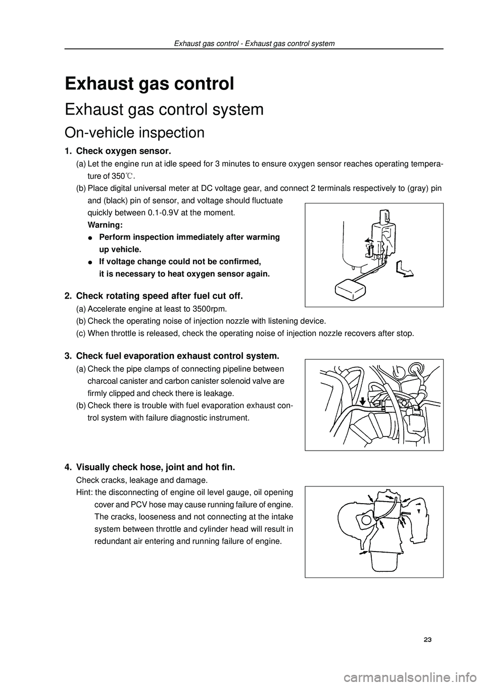
Exhaust gas controlExhaust gas control systemOn-vehicle inspection1. Check oxygen sensor.(a) Let the engine run at idle speed for 3 minutes to ensure oxygen sensor reaches operating tempera-
ture of 350(b) Place digital universal meter at DC voltage gear, and connect 2 terminals respectively to (gray) pin
and (black) pin of sensor, and voltage should fluctuate
quickly between 0.1-0.9V at the moment.
Warning:Perform inspection immediately after warming
up vehicle.If voltage change could not be confirmed,
it is necessary to heat oxygen sensor again.Exhaust gas control - Exhaust gas control system2. Check rotating speed after fuel cut off.(a) Accelerate engine at least to 3500rpm.
(b) Check the operating noise of injection nozzle with listening device.
(c) When throttle is released, check the operating noise of injection nozzle recovers after stop.3. Check fuel evaporation exhaust control system.(a) Check the pipe clamps of connecting pipeline between
charcoal canister and carbon canister solenoid valve are
firmly clipped and check there is leakage.
(b) Check there is trouble with fuel evaporation exhaust con-
trol system with failure diagnostic instrument.4. Visually check hose, joint and hot fin.Check cracks, leakage and damage.
Hint: the disconnecting of engine oil level gauge, oil opening
cover and PCV hose may cause running failure of engine.
The cracks, looseness and not connecting at the intake
system between throttle and cylinder head will result in
redundant air entering and running failure of engine.23
Page 36 of 419
 Blow air into valve from cylinder side and check the air is
easy to get through.
Warning: do not suck against th GEELY FC 2008 Workshop Manual Exhaust gas control - Exhaust gas control system3. PCV valve assembly [4G18-1014110](a) Blow air into valve from cylinder side and check the air is
easy to get through.
Warning: do not suck against th](/img/58/57161/w960_57161-35.png)
Exhaust gas control - Exhaust gas control system3. PCV valve assembly [4G18-1014110](a) Blow air into valve from cylinder side and check the air is
easy to get through.
Warning: do not suck against the valve, because the
gasoline left in the valve will make you be
injured.
(b) Blow air into valve from intake manifold side and check
the air is hard to get through.
Hint: if the function does not conform to the standard, PCV
valve should be replaced.Inspection1. Carbon canister assembly [4G18-1129020]Carbonl canister assembly. Check the function of carbon can-
ister according to the following tables.
Standard:2. Carbon canister control valve(a) For carbon canister control valve, check the conduction be-
tween terminals.
Resistance: (b) Check the control valve operates.
(1) Supply battery voltage to its terminal.
(2) Check air is flown as the arrow direction on valve body. 25Inspection Methods Standard
Close B hole and C hole and then
supply vacuum to A hole No leakage
Close C hole and then supply vacuum Air flown out
to A hole from B hole
Close C hole and then blow air Air flown out
into A hole from B hole
Blow air into A hole Air flown out from B hole
and C holeClean hose Cylinder side
Intake manifold side
Page 65 of 419
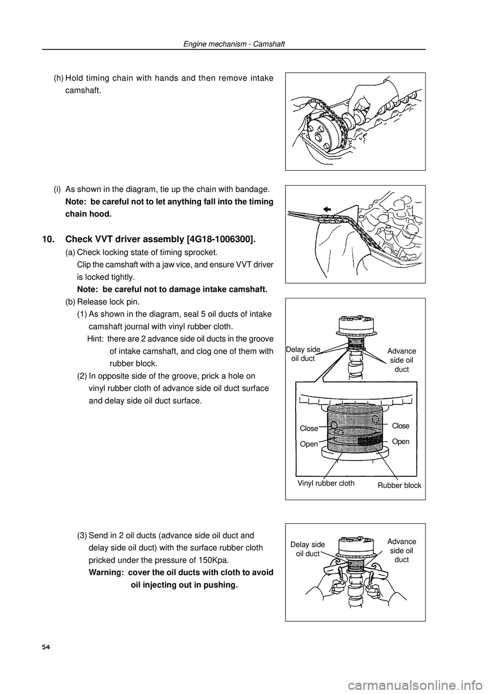
Engine mechanism - Camshaft(h) Hold timing chain with hands and then remove intake
camshaft.
(i) As shown in the diagram, tie up the chain with bandage.
Note: be careful not to let anything fall into the timing
chain hood.10. Check VVT driver assembly [4G18-1006300].(a) Check locking state of timing sprocket.
Clip the camshaft with a jaw vice, and ensure VVT driver
is locked tightly.
Note: be careful not to damage intake camshaft.
(b) Release lock pin.
(1) As shown in the diagram, seal 5 oil ducts of intake
camshaft journal with vinyl rubber cloth.
Hint: there are 2 advance side oil ducts in the groove
of intake camshaft, and clog one of them with
rubber block.
(2) In opposite side of the groove, prick a hole on
vinyl rubber cloth of advance side oil duct surface
and delay side oil duct surface.
(3) Send in 2 oil ducts (advance side oil duct and
delay side oil duct) with the surface rubber cloth
pricked under the pressure of 150Kpa.
Warning: cover the oil ducts with cloth to avoid
oil injecting out in pushing.54Delay side
oil ductAdvance
side oil
duct
Close
OpenClose
Open
Vinyl rubber cloth
Rubber blockDelay side
oil ductAdvance
side oil
duct
Page 66 of 419
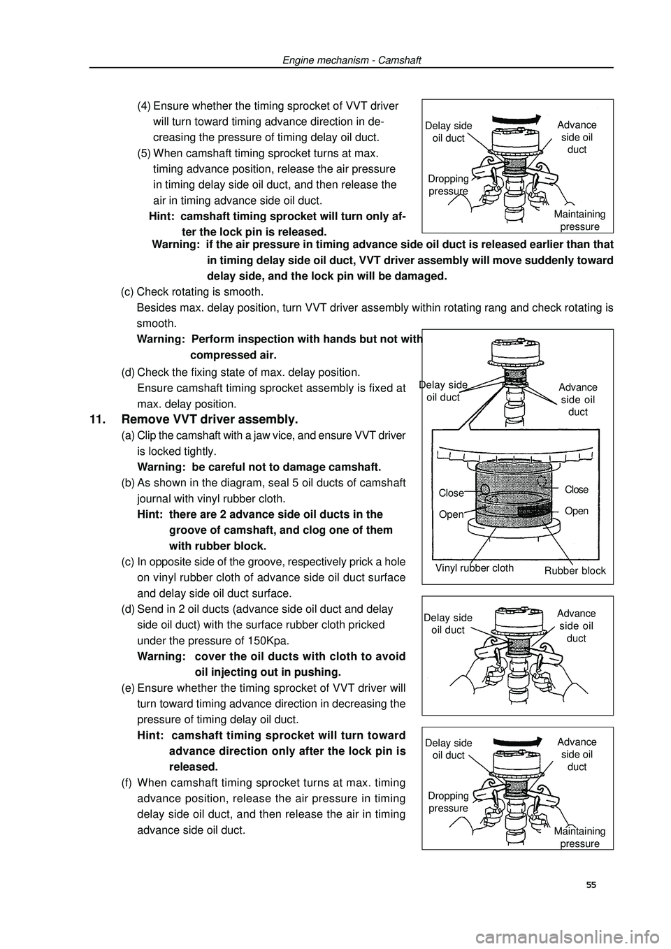
Engine mechanism - Camshaft(4) Ensure whether the timing sprocket of VVT driver
will turn toward timing advance direction in de-
creasing the pressure of timing delay oil duct.
(5) When camshaft timing sprocket turns at max.
timing advance position, release the air pressure
in timing delay side oil duct, and then release the
air in timing advance side oil duct.
Hint: camshaft timing sprocket will turn only af-
ter the lock pin is released.
(d) Check the fixing state of max. delay position.
Ensure camshaft timing sprocket assembly is fixed at
max. delay position.11. Remove VVT driver assembly.(a) Clip the camshaft with a jaw vice, and ensure VVT driver
is locked tightly.
Warning: be careful not to damage camshaft.
(b) As shown in the diagram, seal 5 oil ducts of camshaft
journal with vinyl rubber cloth.
Hint: there are 2 advance side oil ducts in the
groove of camshaft, and clog one of them
with rubber block.
(c) In opposite side of the groove, respectively prick a hole
on vinyl rubber cloth of advance side oil duct surface
and delay side oil duct surface.
(d) Send in 2 oil ducts (advance side oil duct and delay
side oil duct) with the surface rubber cloth pricked
under the pressure of 150Kpa.
Warning:cover the oil ducts with cloth to avoid
oil injecting out in pushing.
(e) Ensure whether the timing sprocket of VVT driver will
turn toward timing advance direction in decreasing the
pressure of timing delay oil duct.
Hint: camshaft timing sprocket will turn toward
advance direction only after the lock pin is
released.
(f) When camshaft timing sprocket turns at max. timing
advance position, release the air pressure in timing
delay side oil duct, and then release the air in timing
advance side oil duct. Warning: if the air pressure in timing advance side oil duct is released earlier than that
in timing delay side oil duct, VVT driver assembly will move suddenly toward
delay side, and the lock pin will be damaged.
(c) Check rotating is smooth.
Besides max. delay position, turn VVT driver assembly within rotating rang and check rotating is
smooth.
Warning: Perform inspection with hands but not with
compressed air.55Delay side
oil ductAdvance
side oil
duct
Close
OpenClose
Open
Vinyl rubber cloth
Rubber block
Delay side
oil ductAdvance
side oil
ductDropping
pressure
Maintaining
pressure Delay side
oil ductAdvance
side oil
duct
Dropping
pressure
Maintaining
pressure Delay side
oil ductAdvance
side oil
duct
Page 67 of 419
Engine mechanism - CamshaftWarning: if the air pressure in timing advance side oil duct is released earlier than that in
timing delay side oil duct, VVT driver assembly will move suddenly toward
delay side.This will cause the damage of lock pin.
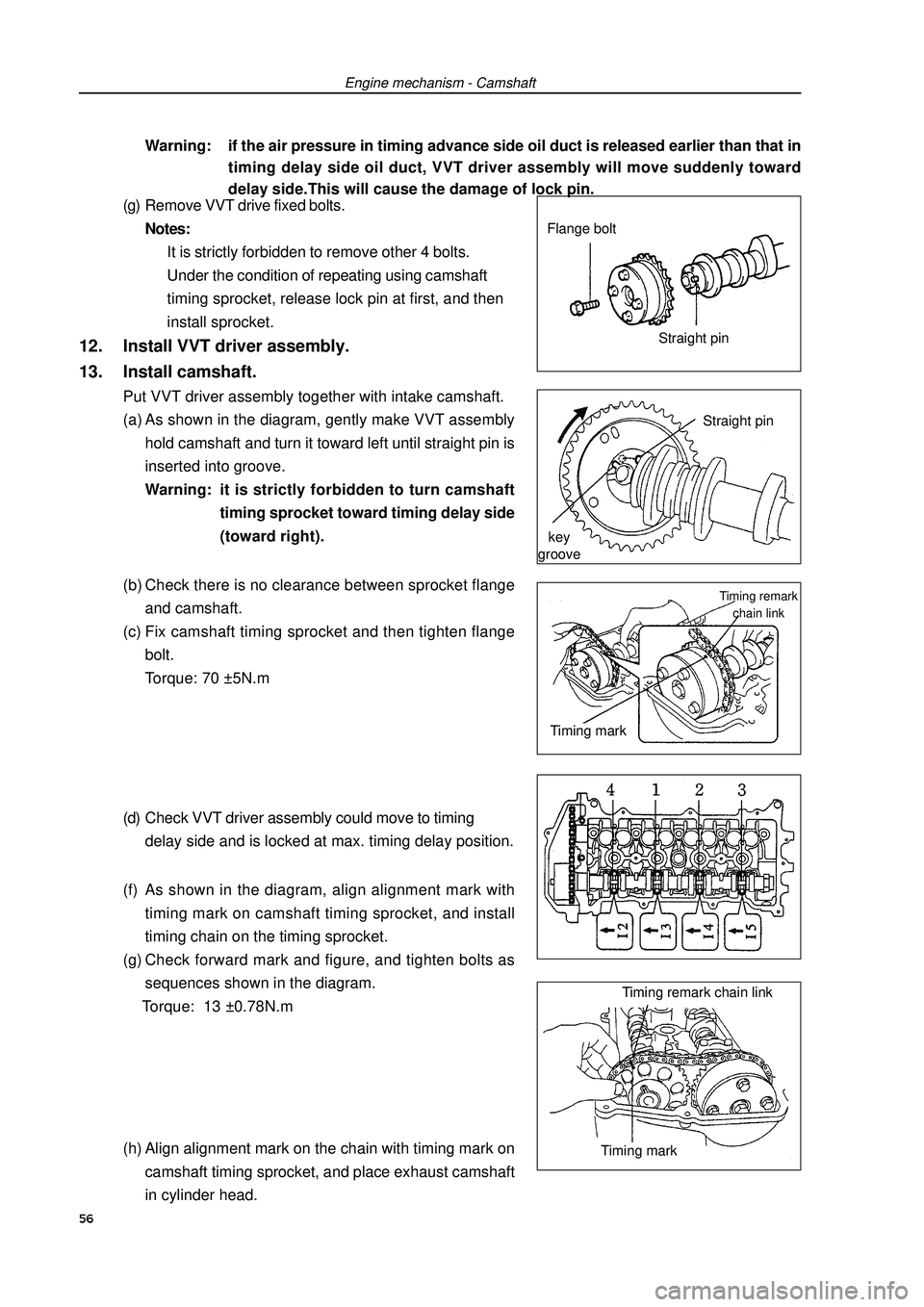
(g) Remove VVT drive fixed bolts.
Notes:
It is strictly forbidden to remove other 4 bolts.
Under the condition of repeating using camshaft
timing sprocket, release lock pin at first, and then
install sprocket.12. Install VVT driver assembly.
13. Install camshaft.Put VVT driver assembly together with intake camshaft.
(a) As shown in the diagram, gently make VVT assembly
hold camshaft and turn it toward left until straight pin is
inserted into groove.
Warning: it is strictly forbidden to turn camshaft
timing sprocket toward timing delay side
(toward right).
(b) Check there is no clearance between sprocket flange
and camshaft.
(c) Fix camshaft timing sprocket and then tighten flange
bolt.
Torque: 70 ±5N.m
(d) Check VVT driver assembly could move to timing
delay side and is locked at max. timing delay position.
(f) As shown in the diagram, align alignment mark with
timing mark on camshaft timing sprocket, and install
timing chain on the timing sprocket.
(g) Check forward mark and figure, and tighten bolts as
sequences shown in the diagram.
Torque: 13 ±0.78N.m
(h) Align alignment mark on the chain with timing mark on
camshaft timing sprocket, and place exhaust camshaft
in cylinder head.Straight pin
key
grooveFlange bolt
Straight pin56Timing remark
chain linkTiming mark
Timing remark chain link
Timing mark
Page 77 of 419
Cooling - Cooling syste2. Check engine coolant level in reservoir.Engine coolant level should be between “Low” and “Full” mark line.
Hint: if the level is too low, check there is leakage and refill coolant to “Full” mark line.3. Check engine coolant quality.(a) Remove radiator cap.
Warning: when the temperature of engine and radiator is high, do not remove radiator cap to
avoid being scalded, because coolant and steam will spurt under high pressure.
(b) Check there is too much rust deposit around radiator cap or at outlet and check there is flake; there
should not be oil in the coolant.
Hint: if coolant is too dirty, it is required to replace coolant.
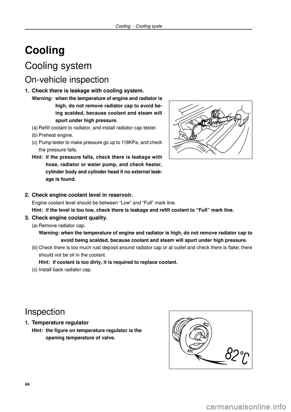
(c) Install back radiator cap.Inspection1. Temperature regulatorHint: the figure on temperature regulator is the
opening temperature of valve.CoolingCooling systemOn-vehicle inspection1. Check there is leakage with cooling system.Warning: when the temperature of engine and radiator is
high, do not remove radiator cap to avoid be-
ing scalded, because coolant and steam will
spurt under high pressure.
(a) Refill coolant to radiator, and install radiator cap tester.
(b) Preheat engine.
(c) Pump tester to make pressure go up to 118KPa, and check
the pressure falls.
Hint: if the pressure falls, check there is leakage with
hose, radiator or water pump, and check heater,
cylinder body and cylinder head if no external leak-
age is found.66
Page 84 of 419
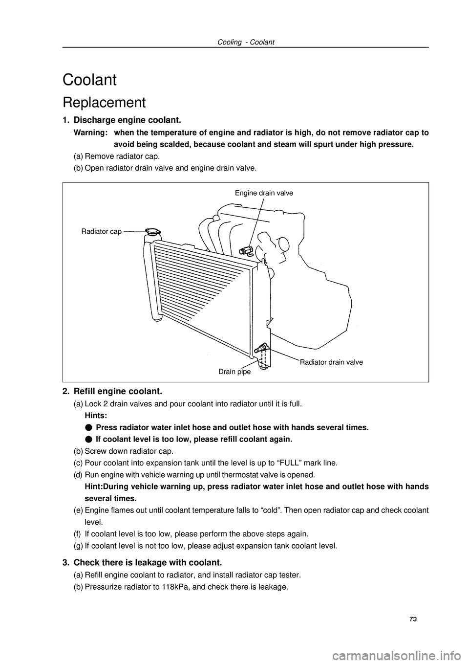
CoolantReplacement1. Discharge engine coolant.Warning: when the temperature of engine and radiator is high, do not remove radiator cap to
avoid being scalded, because coolant and steam will spurt under high pressure.
(a) Remove radiator cap.
(b) Open radiator drain valve and engine drain valve.Cooling - Coolant2. Refill engine coolant.(a) Lock 2 drain valves and pour coolant into radiator until it is full.
Hints:Press radiator water inlet hose and outlet hose with hands several times.If coolant level is too low, please refill coolant again.
(b) Screw down radiator cap.
(c) Pour coolant into expansion tank until the level is up to “FULL” mark line.
(d) Run engine with vehicle warning up until thermostat valve is opened.
Hint:During vehicle warning up, press radiator water inlet hose and outlet hose with hands
several times.
(e) Engine flames out until coolant temperature falls to “cold”. Then open radiator cap and check coolant
level.
(f) If coolant level is too low, please perform the above steps again.
(g) If coolant level is not too low, please adjust expansion tank coolant level.3. Check there is leakage with coolant.(a) Refill engine coolant to radiator, and install radiator cap tester.
(b) Pressurize radiator to 118kPa, and check there is leakage.73Engine drain valve
Radiator drain valve Radiator cap
Drain pipe