automatic transmission GEELY MK 2008 User Guide
[x] Cancel search | Manufacturer: GEELY, Model Year: 2008, Model line: MK, Model: GEELY MK 2008Pages: 416, PDF Size: 25.19 MB
Page 74 of 416

Figure 7-93-33Replacement1. Discharge the automatic transmission oil.
(1) Remove the discharge plug and washer to discharge the ATF oil.
(2) Install the discharge plug and new washer.
Torque: 25N.m
2. Remove the front wheel.
3. Remove the left/right front wheel hub nuts.
4. Unfix the front stabilizer bar.
5. Unfix #1 left/ring front suspension sub-assembly.
6. Unfix the left/right ball extension rod sub-assembly.
7. Unfix the left/right front axles.
8. Remove the differential front oil seal (on the transaxle housing).Section 3 Differential Front Oil Seal (ATM)1. Check the hydraulic torque converter assembly.
(1)Measure the status of the hydraulic torque converter.
(2)Replace the ATF in the hydraulic torque converter.
(3)Wash and check oil freezer and oil pipe.
(4)Prevent the hydraulic torque converter being deformed and
the oil pump gear being damaged.
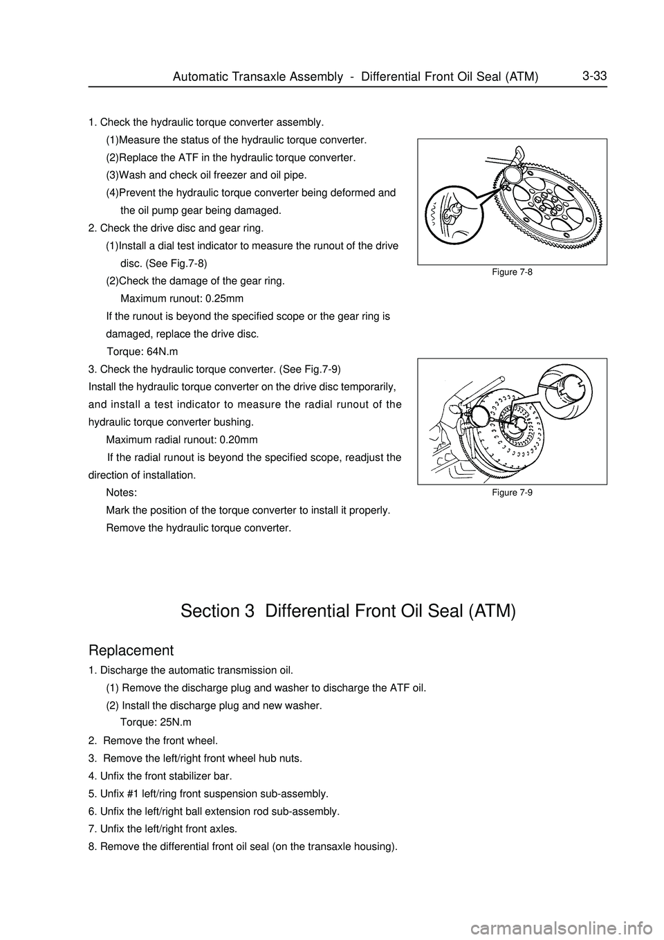
2. Check the drive disc and gear ring.
(1)Install a dial test indicator to measure the runout of the drive
disc. (See Fig.7-8)
(2)Check the damage of the gear ring.
Maximum runout: 0.25mm
If the runout is beyond the specified scope or the gear ring is
damaged, replace the drive disc.
Torque: 64N.m
3. Check the hydraulic torque converter. (See Fig.7-9)
Install the hydraulic torque converter on the drive disc temporarily,
and install a test indicator to measure the radial runout of the
hydraulic torque converter bushing.
Maximum radial runout: 0.20mm
If the radial runout is beyond the specified scope, readjust the
direction of installation.
Notes:
Mark the position of the torque converter to install it properly.
Remove the hydraulic torque converter.Figure 7-8Automatic Transaxle Assembly Differential Front Oil Seal (ATM) -
Page 75 of 416

9. Pull out oil seal (on the transaxle housing) with a special tool.
(See Fig.7-10)
10. Remove the differential front oil seal on the transmission housing.
Pull out the oil seal on the transmission housing with a special
tool. (See Fig.7-11)
11. Install the differential front oil seal onto the transmission housing.
(1) Install a new oil seal on the transmission housing with a
special tool and hammer. (See Fig.7-12)
(2) Apply MP lube on the flange of the oil seal.
12. Install the differential front oil seal onto the transmission housing.
(1) Install a new oil seal onto the transmission housing with a
special tool and hammer. (See Fig.7-13)
(2) Apply MP lube on the flange of the oil seal.Figure 7-10
Figure 7-11
Figure 7-12Figure 7-13Automatic Transaxle Assembly Differential Front Oil Seal (ATM)3-3413. Install all parts in the sequence of removal till the front wheel is installed, and then add transmission oil.
14. Check and adjust the alignment of the front wheel. -
Page 77 of 416

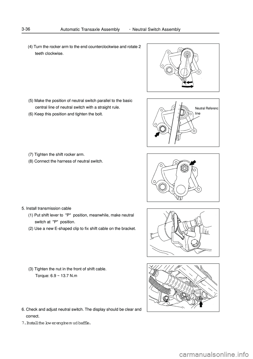
Automatic Transaxle Assembly Neutral Switch Assembly3-36 (4) Turn the rocker arm to the end counterclockwise and rotate 2
teeth clockwise.
(5) Make the position of neutral switch parallel to the basic
central line of neutral switch with a straight rule.
(6) Keep this position and tighten the bolt.
(7) Tighten the shift rocker arm.
(8) Connect the harness of neutral switch.
5. Install transmission cable
(1) Put shift lever to "P" position, meanwhile, make neutral
switch at "P" position.
(2) Use a new E-shaped clip to fix shift cable on the bracket.
(3) Tighten the nut in the front of shift cable.
Torque: 6.9 ~ 13.7 N.m
6. Check and adjust neutral switch. The display should be clear and
correct.
7. Install the lower engine mud baffle.Neutral Referencline -
Page 84 of 416

Transmission ControlAutomatic Transmission Shift Mechanism4-7Section 4 Automatic Transmission Shift MechanismComponent ViewConsole Panel Upper
Cover Assembly E Clip
Console Panel Lower
Cover Assembly
Cup Holder
Park Brake Cover Plate
E Clip
Console Assembly
Automatic Shifter Assembly121212 Shift Cable Key Retaining Cable E Clip
Specified Torque -
Page 85 of 416

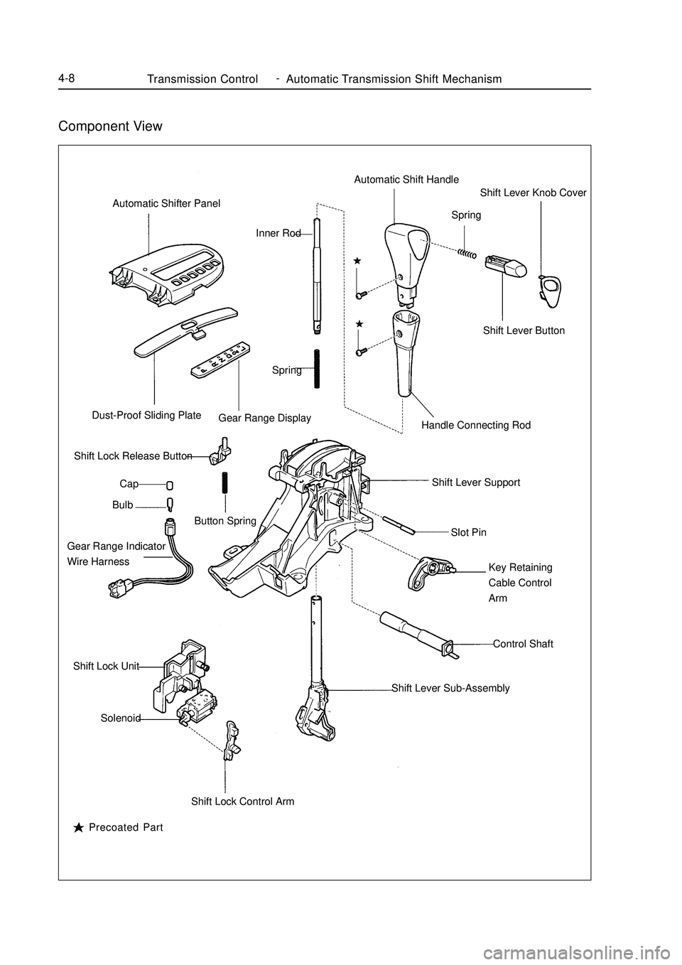
Transmission ControlAutomatic Transmission Shift Mechanism4-8Component ViewAutomatic Shifter Panel
Dust-Proof Sliding Plate
Gear Range Display
Shift Lock Release Button
Cap
Bulb
Button Spring
Gear Range Indicator
Wire Harness
Shift Lock Unit
Solenoid
Shift Lock Control ArmShift Lever Sub-AssemblyControl Shaft Key Retaining
Cable Control
Arm Slot Pin Shift Lever SupportHandle Connecting RodShift Lever Button Shift Lever Knob Cover
Spring Automatic Shift Handle
Spring Inner Rod
Precoated Part -
Page 86 of 416

Transmission ControlAutomatic Transmission Shift Mechanism4-9Replacement1. Remove CD cover
2. Remove console panel lower cover assembly
3. Remove cup holder
4. Remove console assembly
5. Remove key retaining cable.
(1) loosen the adjustment locking cap.
Tip:
Face the vehicle front and turn rotate it clockwise by 90°.
(2) Use screwdriver to remove the key retaining cable
6. Disconnect shift cable assembly
(1) Remove the nut, disconnect the shift cable from the shifter
assembly
(2) Use screwdriver to disconnect the shift cable from the shift
lever tray.
7. Remove automatic shifter assembly
(1) Remove the four bolts.
(2) Disconnect the two connectors.
(3) Remove the shifter assembly. -
Page 87 of 416

4-108. Install the automatic shifter assembly
Install it in place in the reverse order of removal.
9. Check and adjust the shift lever position
(1) Check that the starter works only when the shift lever is in P position, but doesn't work in other positions.
(2) Move the shift lever, check whether the display of the gear range indicator is consistent with the actual gear
range.
(3) Check that the key can be pulled out in P position.
(4) Except the P position, the ignition key can not be turned to LOCK position with the shift lever in other
positions.
(5) Check that when shift release button is pressed down, the shift lever can be transferred to other positions
from the P position.
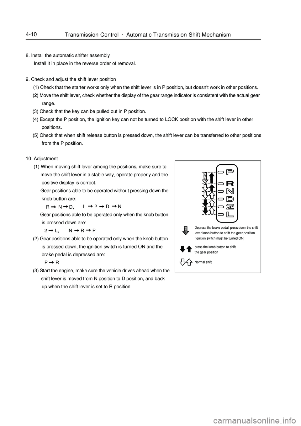
10. Adjustment
(1) When moving shift lever among the positions, make sure to
move the shift lever in a stable way, operate properly and the
positive display is correct.
Gear positions able to be operated without pressing down the
knob button are:
R N D,L 2 D N
Gear positions able to be operated only when the knob button
is pressed down are:
2 L,N R P
(2) Gear positions able to be operated only when the knob button
is pressed down, the ignition switch is turned ON and the
brake pedal is depressed are:
P R
(3) Start the engine, make sure the vehicle drives ahead when the
shift lever is moved from N position to D position, and back
up when the shift lever is set to R position.Depress the brake pedal, press down the shift
lever knob button to shift the gear position.
(ignition switch must be turned ON)
press the knob button to shift
the gear position
Normal shiftTransmission ControlAutomatic Transmission Shift Mechanism -
Page 98 of 416

Overhaul1. Drain manual transmission oil (M/T transmission)
Torque: 39N.m
2. Drain automatic transmission oil (A/T transmission)
Torque: 25N.m
3. Remove front wheel
4. Remove engine bottom left shield (M/T transaxle)
5. Remove engine bottom right shield (M/T transaxle)
6. Remove engine bottom shield assembly (A/T transaxle)
7. Remove front wheel hub left bolt
(1) Using a hammer and a drive shaft nut chisel, unstake the
staked part of the left wheel hub nut.
(2) While applying the brake pedal, remove the left wheel hub
nut.
Notice: the staked part of the nut should be fully unstaked,
otherwise it may damage the thread of the drive shaft.
8. Remove left front vehicle speed sensor (with ABS)
(1) Remove the bolt and clip, remove vehicle speed sensor and
brake hose from left front shock absorber assembly.
(2) Remove the bolt, separate the left front vehicle speed sensor
from steering knuckle.
9. Remove front stabilizer bar
(1) Use a 10mm wrench to hold the bolt, remove the nut
(2) Remove two collars, No.1 and No.2 gaskets, remove front
stabilizer barPropeller Shaft/DriveshaftFront Driveshaft4-21 -
Page 105 of 416

Propeller Shaft/DriveshaftFront Driveshaft4-28 Hint:
Please refer to the following table for dimension (A).LH mm
528.3±5.0
527.0±5.0RH mm
859.3±5.0
860.0±5.0 M/T manual transmission
A/T automatic transmission38. Install left constant velocity drive shaft assembly
(1) M/T
Coat the spline of the tripod joint assembly with gear oil.
(2) A/T
Coat the spline of the tripod joint assembly with ATF
(Automatic Transmission Fluid).
(3) Align the spline, use a brass bar and hammer to install the left
drive shaft assembly.
Notice:
Face the retainer open end downward.
Be careful not to damage the boot and oil seal.
Hint:
You can find out whether the tripod joint shaft contact the pinion shaft by rotating the shaft assembly, listening
to the sound and feeling.
39. Install right constant velocity drive shaft assembly
Hint:
The installation of the right side is the same as that of the left side.
Notice:
Install the retainer with its open end facing downward.
Be careful not to damage the boot and oil seal.
40. Install left steering knuckle assembly
Install the left constant velocity drive shaft assembly on the left steering knuckle assembly.
Notice:
Be careful not to damage the outboard joint boot.
With ABS:
Be careful not to damage the vehicle speed sensor rotor.
41. Install left steering gear with tie rod assembly
(1) Install the steering gear with tie rod assembly on the steering knuckle assembly with nuts.
Torque: 33N.m
(2) Install the new cotter pins.
Notice:
If the pin holes are not aligned, further tighten the nut by 60°.
42. Install left lower swing arm assembly
(1) Install the left lower swing arm assembly on the steering knuckle assembly with nuts.
Torque: 98N.m -
Page 106 of 416

Propeller Shaft/DriveshaftFront Driveshaft4-29 (2) Install the new cotter pins.
Notice:
If the pin holes are not aligned, further tighten the nut by 60°.
43. Install front stabilizer bar
(1) As shown in the illustration, install the stabilizer bar with two
No.1 collars and two gaskets and nuts.
Notice:
Make sure the gaskets and collars are correctly installed.
(2) Tighten the nut with a 10mm wrench.
Torque: 18N.m
44. Install left front vehicle speed sensor (with ABS)
(1) Install the left front vehicle speed sensor and brake hose on the
front shock absorber with bolts and clps.
Torque: 29N.m
(2) Install the vehicle speed sensor on the steering knuckle with
bolts.
Torque: 8.0N.m
Notice:
Be careful not to damage the wheel speed sensor.
Keep the vehicle speed sensor clean.
When installing the sensor,do not twist the sensor wire harness.
45. Install left steering knuckle wheel hub nut
(1) Install new left steering knuckle hub nuts
Torque: 216N.m
(2) Using a chisel and hammer, stake the hub locking nut.
46. Install engine bottom left shield
47. Install engine bottom right shield
48. Install engine bottom shield assembly
49. Install front wheel
Torque: 103 N.m
50. Add oil into manual transmission
51. Check and adjust the manual transmission fluid
52. Refill automatic transmission fluid
53. Check and adjust the automatic transmission fluid
54. Check and adjust front wheel alignment
55. Check ABS vehicle speed signal (with ABS) -