automatic transmission GEELY MK 2008 Workshop Manual
[x] Cancel search | Manufacturer: GEELY, Model Year: 2008, Model line: MK, Model: GEELY MK 2008Pages: 416, PDF Size: 25.19 MB
Page 3 of 416
Geely “MK” series sedans (JL7132U,JL7132HU,JL7152U,JL7152HU,JL7162U) are brand
new superior models developed by Geely Group who has fully proprietary intellectual property
rights. As a result of the three years of involvements and efforts of the experts from Geely Automo-
bile Research Institute, these sedans reach international leading level in model design, power,
sense of comfort, safety and manufacturing technology while featured in beautiful appearance,
economy, environment protection and safety. The meaning of MK implied that Geely Automobile
has a great development from caterpillar to butterfly. With respect to the power, Geely “MK” series
sedans are equipped with 1.3L, 1.5L, and 1.6L EFI engines developed and manufactured by Geely
itself, and has reached “Chinese III” (Euro III) emission standard.
This manual contains a detailed description of the structures and principles, servicing and adjustment,
removal, assembling technology and matching clearance of the parts of the Geely “MK” sedans
with torque information of the bolts and nuts as well as schematic diagram for special tool operation.
This manual also introduces the transmission control system of the automatic transmission models,
vehicle electric circuits and elaborates ABS system, SRS, BOSCH M7.9.7 electronic control fuel
injection and ignition system, rear parking radar, sound, air conditioning and onboard hands-free
phone system. You can refer to this manual for the information about the regular maintenance,
servicing, adjustment, troubleshooting, removal and installation procedure, specific operations of
the “MK” sedans.
This manual covers the matching relation among the engine assembly, transmission assembly and
the vehicle, but does not have the further description of the structures and principles of the engine
and transmission assemblies and their servicing process. You can refer to the service manuals
solely prepared for engine assembly and transmission assembly for these information.
All information in this manual is based on the latest products released at the time of publication of
this manual. However, the specifications and procedures may need to be modified, and the subse-
quent change will be revealed in later versions.
This manual is prepared by Geely Automobile Research Institute under the assistance of technical
staff from Zhejiang Geely Automobile Co., Ltd and Geely International Corporation. Readers
discovering during the use of this manual the errors and careless omissions due to limited skills of
the preparers and tight schedule are encouraged and pled to contact Geely International in time for
our timely correction of the mistakes.ForewordGeely International Corporation
Nov . 2007
Page 5 of 416
Table of Contents II Section 4 Fuel Emission Control System ....................................................................... 3-18
Section 5 Carbon Canister Replacement ....................................................................... 3-19
Chapter 4 Exhaust System................................................................................................. 3-21
Chapter 5 Cooling System................................................................................................. 3-22
Section 1 System Inspection .......................................................................................... 3-22
Section 2 Radiator Replacement ................................................................................... 3-24
Chapter 6 Manual Transaxle Assembly............................................................................. 3-25
Section 1 Frequent Problem Diagnosis .......................................................................... 3-25
Section 2 Vehicle Speed Sensor Replacement ............................................................. 3-26
Section 3 Manual Transaxle Replacement ..................................................................... 3-27
Section 4 Transmission/Transaxle Case Oil Seal Replacement .................................... 3-28
Chapter 7 Automatic Transaxle Assembly........................................................................ 3-29
Section 1 Frequent Problems Diagnosis ........................................................................ 3-29
Section 2 Hydraulic Torque Converter and Transaxle .................................................... 3-30
Section 3 Differential Front Oil Seal (ATM) .................................................................... 3-33
Section 4 Neutral Switch Assembly ................................................................................ 3-35Part IV ChassisChapter 1 Transmission Control........................................................................................ 4-1
Section 1 Introduction of Transmission Control ............................................................. 4-1
Section 2 Cable Type Transmission Control .................................................................. 4-3
Section 3 Manual Transmission Shift Mechanism .......................................................... 4-5
Section 4 Automatic Transmission Shift Mechanism ...................................................... 4-7
Chapter 2 Accelerator Pedal Device................................................................................. 4-11
Section 1 Introduction of Accelerator Pedal ................................................................... 4-11
Chapter 3 Clutch Control System...................................................................................... 4-12
Section 1 Introduction of Clutch Centrol ......................................................................... 4-12
Section 2 Clutch Pedal ...................................................................................................4-13
Chapter 4 Propeller Shaft/Driveshaft................................................................................ 4-17
Section 1 Propeller Shaft, Driveshaft and Transaxle ..................................................... 4-17
Page 27 of 416
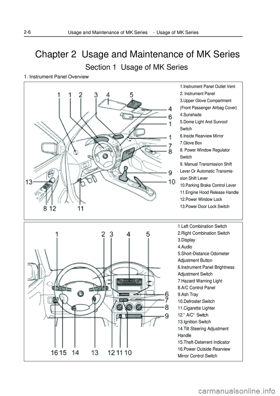
Chapter 2 Usage and Maintenance of MK SeriesSection 1 Usage of MK Series1. Instrument Panel Overview1.Instrument Panel Outlet Vent
2. Instrument Panel
3.Upper Glove Compartment
(Front Passenger Airbag Cover)
4.Sunshade
5.Dome Light And Sunroof
Switch
6.Inside Rearview Mirror
7.Glove Box
8. Power Window Regulator
Switch
9. Manual Transmission Shift
Lever Or Automatic Transmis-
sion Shift Lever
10.Parking Brake Control Lever
11.Engine Hood Release Handle
12.Power Window Lock
13.Power Door Lock Switch1.Left Combination Switch
2.Right Combination Switch
3.Display
4.Audio
5.Short-Distance Odometer
Adjustment Button
6.Instrument Panel Brightness
Adjustment Switch
7.Hazard Warning Light
8.A/C Control Panel
9.Ash Tray
10.Defroster Switch
11.Cigarette Lighter
12.”A/C“ Switch
13.Ignition Switch
14.Tilt Steering Adjustment
Handle
15.Theft-Deterrent Indicator
16.Power Outside Rearview
Mirror Control SwitchUsage and Maintenance of MK Series - Usage of MK Series2-6
Page 36 of 416
2-15
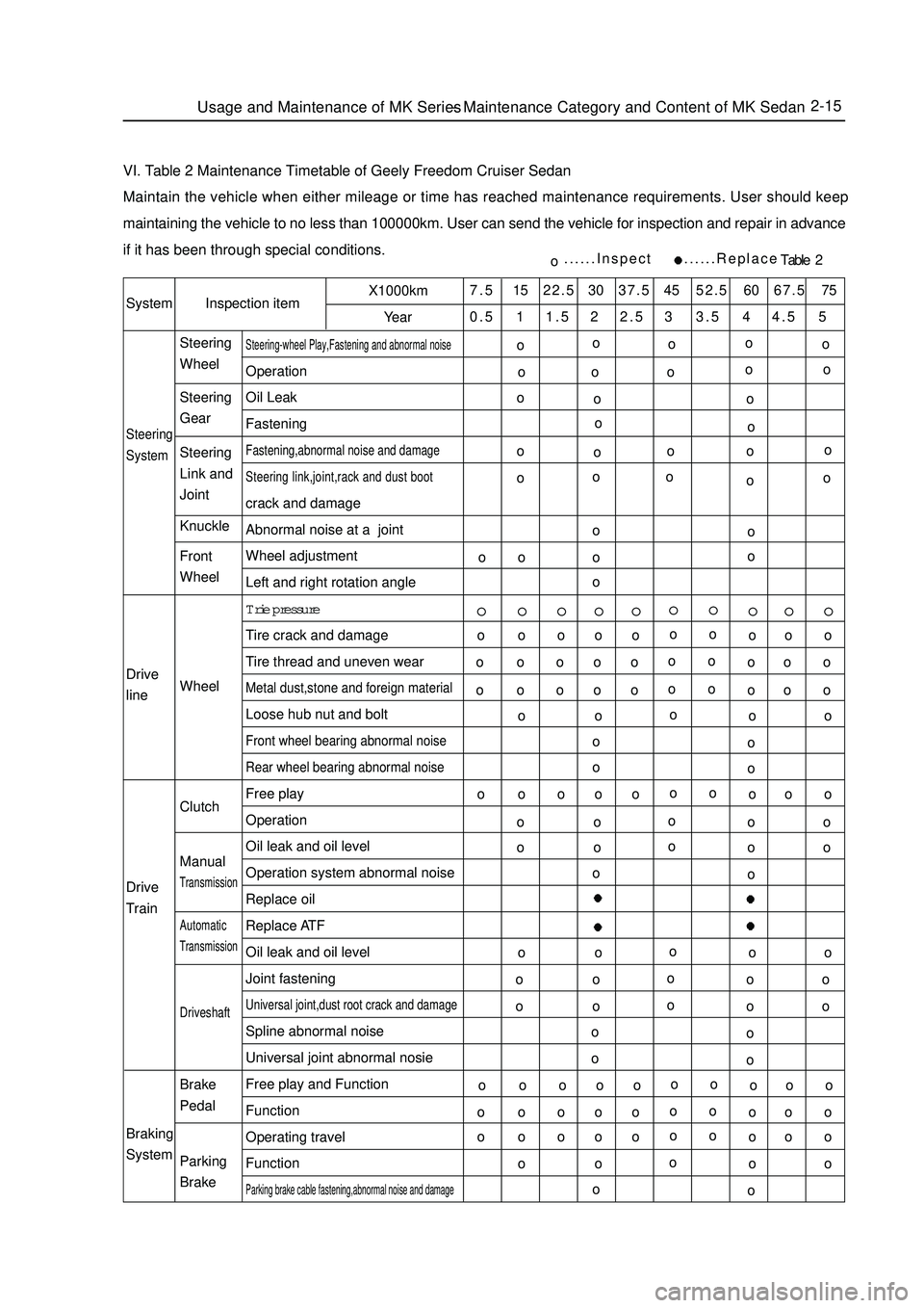
VI. Table 2 Maintenance Timetable of Geely Freedom Cruiser SedanMaintain the vehicle when either mileage or time has reached maintenance requirements. User should keep
maintaining the vehicle to no less than 100000km. User can send the vehicle for inspection and repair in advance
if it has been through special conditions.SystemInspection itemX1000km
Year7.5 15 22.5 30 37.5 45 52.5 60 67.5 75
0.5 1 1.5 2 2.5 3 3.5 4 4.5 5Steering
SystemSteering-wheel Play,Fastening and abnormal noiseOperation
Oil Leak
FasteningFastening,abnormal noise and damage
Steering link,joint,rack and dust bootcrack and damage
Abnormal noise at a joint
Wheel adjustment
Left and right rotation angle
Trie pressure
Tire crack and damage
Tire thread and uneven wearMetal dust,stone and foreign materialLoose hub nut and boltFront wheel bearing abnormal noise
Rear wheel bearing abnormal noiseFree play
Operation
Oil leak and oil level
Operation system abnormal noise
Replace oil
Replace ATF
Oil leak and oil level
Joint fasteningUniversal joint,dust root crack and damageSpline abnormal noise
Universal joint abnormal nosie
Free play and Function
Function
Operating travel
FunctionParking brake cable fastening,abnormal noise and damageo......Inspect ......ReplaceTable 2 Drive
line
Drive
Train
Braking
SystemSteering
Wheel
Steering
Gear
Steering
Link and
Joint
Knuckle
Front
Wheel
Wheel
Clutch
ManualTransmissionAutomaticTransmissionDriveshaftBrake
Pedal
Parking
BrakeUsage and Maintenance of MK Series - Maintenance Category and Content of MK Sedano
o
oo
o o oo o
o o
oo
o o
oo
ooo
o
o oo
o ooo
o o o
o
oo o o o
o o o o
o
oo o o o
o o o o
o
oo o o o
o o o o
o
oo o o o
o o o o
o
oo o o o
o o o o
o
oo o o o
o o o o
o
oo o o o
o o o o
o
oo o o o
o o o o
oo o o
o
o
o o o
o
o
o o o
o
o
o o o
o
o
o o o
o
o
o o o
o
oo o
o o
o o
o o
o o
o oo o o
o
o
Page 38 of 416
2-17
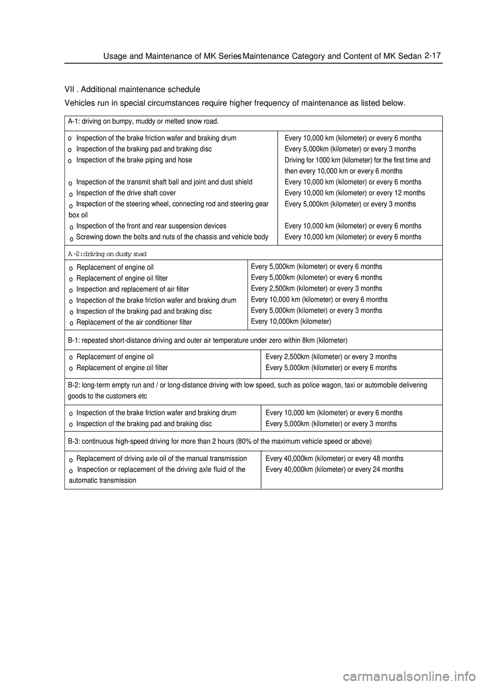
VII . Additional maintenance scheduleVehicles run in special circumstances require higher frequency of maintenance as listed below. Replacement of engine oil
Replacement of engine oil filter B-1: repeated short-distance driving and outer air temperature under zero within 8km (kilometer)
Inspection of the brake friction wafer and braking drum
Inspection of the braking pad and braking disc B-2: long-term empty run and / or long-distance driving with low speed, such as police wagon, taxi or automobile delivering
goods to the customers etcEvery 2,500km (kilometer) or every 3 months
Every 5,000km (kilometer) or every 6 months
Every 10,000 km (kilometer) or every 6 months
Every 5,000km (kilometer) or every 3 monthsB-3: continuous high-speed driving for more than 2 hours (80% of the maximum vehicle speed or above)
Replacement of driving axle oil of the manual transmission
Inspection or replacement of the driving axle fluid of the
automatic transmissionEvery 40,000km (kilometer) or every 48 months
Every 40,000km (kilometer) or every 24 months Inspection of the brake friction wafer and braking drum
Inspection of the braking pad and braking disc
Inspection of the brake piping and hose
Inspection of the transmit shaft ball and joint and dust shield
Inspection of the drive shaft cover
Inspection of the steering wheel, connecting rod and steering gear
box oil
Inspection of the front and rear suspension devices
Screwing down the bolts and nuts of the chassis and vehicle body A-1: driving on bumpy, muddy or melted snow road.
Replacement of engine oil
Replacement of engine oil filter
Inspection and replacement of air filter
Inspection of the brake friction wafer and braking drum
Inspection of the braking pad and braking disc
Replacement of the air conditioner filterA-2: driving on dusty roadEvery 10,000 km (kilometer) or every 6 months
Every 5,000km (kilometer) or every 3 months
Driving for 1000 km (kilometer) for the first time and
then every 10,000 km or every 6 months
Every 10,000 km (kilometer) or every 6 months
Every 10,000 km (kilometer) or every 12 months
Every 5,000km (kilometer) or every 3 months
Every 10,000 km (kilometer) or every 6 months
Every 10,000 km (kilometer) or every 6 months
Every 5,000km (kilometer) or every 6 months
Every 5,000km (kilometer) or every 6 months
Every 2,500km (kilometer) or every 3 months
Every 10,000 km (kilometer) or every 6 months
Every 5,000km (kilometer) or every 3 months
Every 10,000km (kilometer)Usage and Maintenance of MK Series - Maintenance Category and Content of MK Sedanoo o
o o o o
o o
o
o o
o o
o o
o ooo
Page 65 of 416
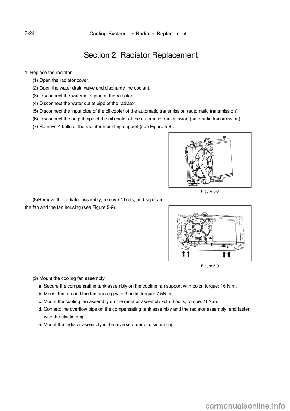
Section 2 Radiator Replacement1. Replace the radiator.
(1) Open the radiator cover.
(2) Open the water drain valve and discharge the coolant.
(3) Disconnect the water inlet pipe of the radiator.
(4) Disconnect the water outlet pipe of the radiator.
(5) Disconnect the input pipe of the oil cooler of the automatic transmission (automatic transmission).
(6) Disconnect the output pipe of the oil cooler of the automatic transmission (automatic transmission).
(7) Remove 4 bolts of the radiator mounting support (see Figure 5-8).Figure 5-8
Figure 5-9Cooling SystemRadiator Replacement3-24 (8)Remove the radiator assembly, remove 4 bolts, and separate
the fan and the fan housing (see Figure 5-9).
(9) Mount the cooling fan assembly.
a. Secure the compensating tank assembly on the cooling fan support with bolts; torque: 16 N.m.
b. Mount the fan and the fan housing with 3 bolts; torque: 7.5N.m.
c. Mount the cooling fan assembly on the radiator assembly with 3 bolts; torque: 16N.m.
d. Connect the overflow pipe on the compensating tank assembly and the radiator assembly, and fasten
with the elastic ring.
e. Mount the radiator assembly in the reverse order of dismounting. -
Page 70 of 416
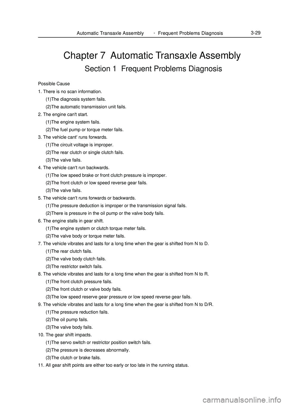
Chapter 7 Automatic Transaxle AssemblySection 1 Frequent Problems DiagnosisPossible Cause1. There is no scan information.
(1)The diagnosis system fails.
(2)The automatic transmission unit fails.
2. The engine can't start.
(1)The engine system fails.
(2)The fuel pump or torque meter fails.
3. The vehicle cant' runs forwards.
(1)The circuit voltage is improper.
(2)The rear clutch or single clutch fails.
(3)The valve fails.
4. The vehicle can't run backwards.
(1)The low speed brake or front clutch pressure is improper.
(2)The front clutch or low speed reverse gear fails.
(3)The valve fails.
5. The vehicle can't runs forwards or backwards.
(1)The pressure deduction is improper or the transmission signal fails.
(2)There is pressure in the oil pump or the valve body fails.
6. The engine stalls in gear shift.
(1)The engine system or clutch torque meter fails.
(2)The valve body or torque meter fails.
7. The vehicle vibrates and lasts for a long time when the gear is shifted from N to D.
(1)The rear clutch fails.
(2)The valve body clutch fails.
(3)The restrictor switch fails.
8. The vehicle vibrates and lasts for a long time when the gear is shifted from N to R.
(1)The front clutch pressure fails.
(2)The front clutch or valve body fails.
(3)The low speed reserve gear pressure or low speed reverse gear fails.
9. The vehicle vibrates and lasts for a long time when the gear is shifted from N to D/R.
(1)The pressure reduction fails.
(2)The oil pump fails.
(3)The valve body fails.
10. The gear shift impacts.
(1)The servo switch or restrictor position switch fails.
(2)The pressure is decreases abnormally.
(3)The clutch or brake fails.
11. All gear shift points are either too early or too late in the running status.Automatic Transaxle Assembly Frequent Problems Diagnosis3-29 -
Page 71 of 416
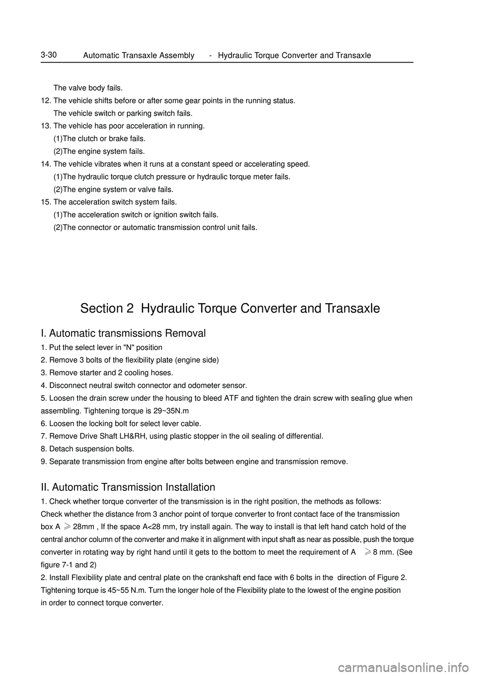
The valve body fails.
12. The vehicle shifts before or after some gear points in the running status.
The vehicle switch or parking switch fails.
13. The vehicle has poor acceleration in running.
(1)The clutch or brake fails.
(2)The engine system fails.
14. The vehicle vibrates when it runs at a constant speed or accelerating speed.
(1)The hydraulic torque clutch pressure or hydraulic torque meter fails.
(2)The engine system or valve fails.
15. The acceleration switch system fails.
(1)The acceleration switch or ignition switch fails.
(2)The connector or automatic transmission control unit fails.I. Automatic transmissions Removal1. Put the select lever in "N" position
2. Remove 3 bolts of the flexibility plate (engine side)
3. Remove starter and 2 cooling hoses.
4. Disconnect neutral switch connector and odometer sensor.
5. Loosen the drain screw under the housing to bleed ATF and tighten the drain screw with sealing glue when
assembling. Tightening torque is 29~35N.m
6. Loosen the locking bolt for select lever cable.
7. Remove Drive Shaft LH&RH, using plastic stopper in the oil sealing of differential.
8. Detach suspension bolts.
9. Separate transmission from engine after bolts between engine and transmission remove.II. Automatic Transmission Installation1. Check whether torque converter of the transmission is in the right position, the methods as follows:
Check whether the distance from 3 anchor point of torque converter to front contact face of the transmission
box A 28mm , If the space A<28 mm, try install again. The way to install is that left hand catch hold of the
central anchor column of the converter and make it in alignment with input shaft as near as possible, push the torque
converter in rotating way by right hand until it gets to the bottom to meet the requirement of A 28 mm. (See
figure 7-1 and 2)
2. Install Flexibility plate and central plate on the crankshaft end face with 6 bolts in the direction of Figure 2.
Tightening torque is 45~55 N.m. Turn the longer hole of the Flexibility plate to the lowest of the engine position
in order to connect torque converter.Section 2 Hydraulic Torque Converter and TransaxleAutomatic Transaxle Assembly Hydraulic Torque Converter and Transaxle3-30 -
Page 72 of 416
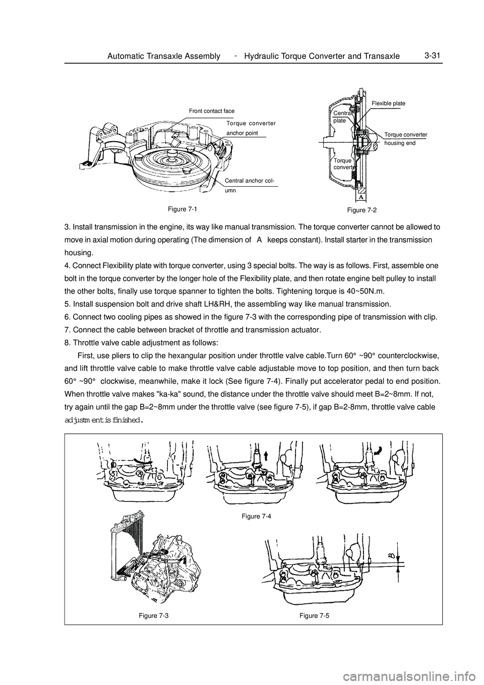
Figure 7-3Automatic Transaxle Assembly Hydraulic Torque Converter and Transaxle3-31Figure 7-5 Figure 7-4Figure 7-1
Figure 7-23. Install transmission in the engine, its way like manual transmission. The torque converter cannot be allowed to
move in axial motion during operating (The dimension of A keeps constant). Install starter in the transmission
housing.
4. Connect Flexibility plate with torque converter, using 3 special bolts. The way is as follows. First, assemble one
bolt in the torque converter by the longer hole of the Flexibility plate, and then rotate engine belt pulley to install
the other bolts, finally use torque spanner to tighten the bolts. Tightening torque is 40~50N.m.
5. Install suspension bolt and drive shaft LH&RH, the assembling way like manual transmission.
6. Connect two cooling pipes as showed in the figure 7-3 with the corresponding pipe of transmission with clip.
7. Connect the cable between bracket of throttle and transmission actuator.
8. Throttle valve cable adjustment as follows:
First, use pliers to clip the hexangular position under throttle valve cable.Turn 60°~90°counterclockwise,
and lift throttle valve cable to make throttle valve cable adjustable move to top position, and then turn back
60°~90° clockwise, meanwhile, make it lock (See figure 7-4). Finally put accelerator pedal to end position.
When throttle valve makes "ka-ka" sound, the distance under the throttle valve should meet B=2~8mm. If not,
try again until the gap B=2~8mm under the throttle valve (see figure 7-5), if gap B=2-8mm, throttle valve cable
adjustment is finished.Central
plateFlexible plate
Torque converter
housing end
Torque
converterFront contact face
Torque converter
anchor point
Central anchor col-
umn -
Page 73 of 416
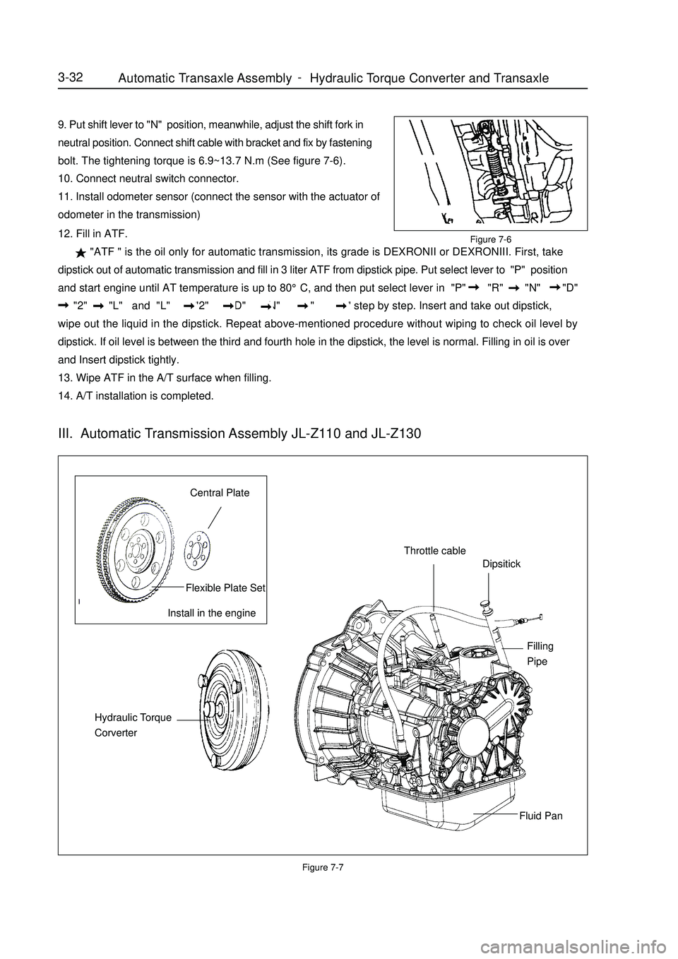
9. Put shift lever to "N" position, meanwhile, adjust the shift fork in
neutral position. Connect shift cable with bracket and fix by fastening
bolt. The tightening torque is 6.9~13.7 N.m (See figure 7-6).
10. Connect neutral switch connector.
11. Install odometer sensor (connect the sensor with the actuator of
odometer in the transmission)Figure 7-712. Fill in ATF.
"ATF " is the oil only for automatic transmission, its grade is DEXRONII or DEXRONIII. First, take
dipstick out of automatic transmission and fill in 3 liter ATF from dipstick pipe. Put select lever to "P" position
and start engine until AT temperature is up to 80°C, and then put select lever in "P" "R" "N" "D"
"2" "L" and "L" "2" "D" "N" "R" "P" step by step. Insert and take out dipstick,
wipe out the liquid in the dipstick. Repeat above-mentioned procedure without wiping to check oil level by
dipstick. If oil level is between the third and fourth hole in the dipstick, the level is normal. Filling in oil is over
and Insert dipstick tightly.
13. Wipe ATF in the A/T surface when filling.
14. A/T installation is completed.3-32Install in the engineCentral PlateFlexible Plate SetThrottle cableDipsitickFilling
PipeFluid Pan Hydraulic Torque
CorverterIII. Automatic Transmission Assembly JL-Z110 and JL-Z130Figure 7-6Automatic Transaxle Assembly Hydraulic Torque Converter and Transaxle -