fuel pressure GEELY MK 2008 User Guide
[x] Cancel search | Manufacturer: GEELY, Model Year: 2008, Model line: MK, Model: GEELY MK 2008Pages: 416, PDF Size: 25.19 MB
Page 56 of 416
Chapter 3 Fuel SystemSection 1 Check Fuel System PressureOn-board inspection
1. Check the operation of the fuel pump.
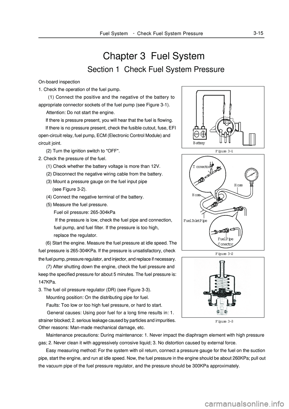
(1) Connect the positive and the negative of the battery to
appropriate connector sockets of the fuel pump (see Figure 3-1).
Attention: Do not start the engine.
If there is pressure present, you will hear that the fuel is flowing.
If there is no pressure present, check the fusible cutout, fuse, EFI
open-circuit relay, fuel pump, ECM (Electronic Control Module) and
circuit joint.
(2) Turn the ignition switch to "OFF".
2. Check the pressure of the fuel.
(1) Check whether the battery voltage is more than 12V.
(2) Disconnect the negative wiring cable from the battery.
(3) Mount a pressure gauge on the fuel input pipe
(see Figure 3-2).
(4) Connect the negative terminal of the battery.
(5) Measure the fuel pressure.
Fuel oil pressure: 265-304kPa
If the pressure is low, check the fuel pipe and connection,
fuel pump, and fuel filter. If the pressure is too high,
replace the regulator.
(6) Start the engine. Measure the fuel pressure at idle speed. The
fuel pressure is 265-304KPa. If the pressure is unsatisfactory, checkFigure 3-1
Figure 3-3 Figure 3-2Fuel SystemCheck Fuel System Pressure3-15the fuel pump, pressure regulator, and injector, and replace if necessary.
(7) After shutting down the engine, check the fuel pressure and
keep the specified pressure for about 5 minutes. The fuel pressure is:
147KPa.
3. The fuel oil pressure regulator (DR) (see Figure 3-3).
Mounting position: On the distributing pipe for fuel.
Faults: Too low or too high fuel pressure, or hard to start.
General causes: Using poor fuel for a long time results in: 1.
strainer blocked; 2. serious leakage caused by particles and impurities.
Other reasons: Man-made mechanical damage, etc.
Maintenance precautions: During maintenance: 1. Never impact the diaphragm element with high pressure
gas; 2. Never clean it with aggressively corrosive liquid; 3. No distortion caused by external force.
Easy measuring method: For the system with oil return, connect a pressure gauge for the fuel on the suction
pipe, start the engine, and run at idle speed. Now, the fuel pressure in the engine should be about 260KPa; pull out
the vacuum pipe of the fuel pressure regulator, and the pressure should be 300KPa approximately.Battery
T conector
Hose
Hose
Fuel Inlet Pipe
Fuel Pipe
Conector -
Page 70 of 416
Chapter 7 Automatic Transaxle AssemblySection 1 Frequent Problems DiagnosisPossible Cause1. There is no scan information.
(1)The diagnosis system fails.
(2)The automatic transmission unit fails.
2. The engine can't start.
(1)The engine system fails.
(2)The fuel pump or torque meter fails.
3. The vehicle cant' runs forwards.
(1)The circuit voltage is improper.
(2)The rear clutch or single clutch fails.
(3)The valve fails.
4. The vehicle can't run backwards.
(1)The low speed brake or front clutch pressure is improper.
(2)The front clutch or low speed reverse gear fails.
(3)The valve fails.
5. The vehicle can't runs forwards or backwards.
(1)The pressure deduction is improper or the transmission signal fails.
(2)There is pressure in the oil pump or the valve body fails.
6. The engine stalls in gear shift.
(1)The engine system or clutch torque meter fails.
(2)The valve body or torque meter fails.
7. The vehicle vibrates and lasts for a long time when the gear is shifted from N to D.
(1)The rear clutch fails.
(2)The valve body clutch fails.
(3)The restrictor switch fails.
8. The vehicle vibrates and lasts for a long time when the gear is shifted from N to R.
(1)The front clutch pressure fails.
(2)The front clutch or valve body fails.
(3)The low speed reserve gear pressure or low speed reverse gear fails.
9. The vehicle vibrates and lasts for a long time when the gear is shifted from N to D/R.
(1)The pressure reduction fails.
(2)The oil pump fails.
(3)The valve body fails.
10. The gear shift impacts.
(1)The servo switch or restrictor position switch fails.
(2)The pressure is decreases abnormally.
(3)The clutch or brake fails.
11. All gear shift points are either too early or too late in the running status.Automatic Transaxle Assembly Frequent Problems Diagnosis3-29 -
Page 196 of 416
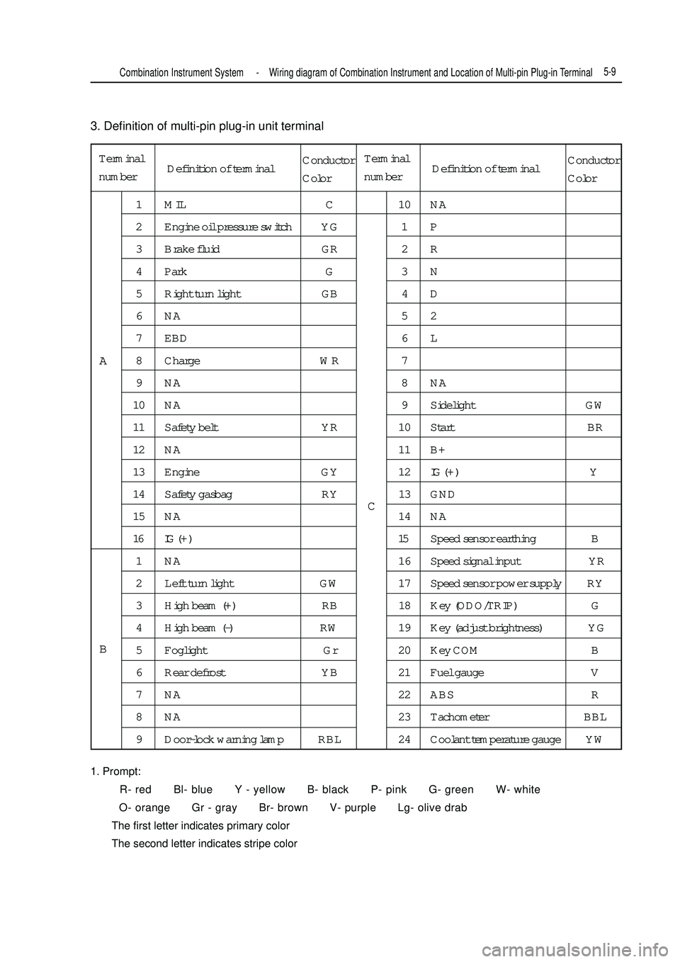
3. Definition of multi-pin plug-in unit terminal
1. Prompt:
R- red Bl- blue Y - yellow B- black P- pink G- green W- white
O- orange Gr - gray Br- brown V- purple Lg- olive drab
The first letter indicates primary color
The second letter indicates stripe colorTerminal
number1 MIL C 10 NA
2 Engine oil pressure switch YG 1 P
3 Brake fluid GR 2 R
4 Park G 3 N
5 Right turn light GB 4 D
6NA 52
7 EBD 6 L
8 Charge WR 7
9NA 8NA
10 NA 9 Sidelight GW
11 Safety belt YR 10 Start BR
12 NA 11 B+
13 Engine GY 12IG ( + ) Y
14 Safety gasbag RY 13 GND
15 NA 14 NA
16 IG ( + ) 15Speed sensor earthing B
1 NA 16 Speed signal input YR
2 Left turn light GW 17 Speed sensor power supply RY
3 High beam (+) RB 18 Key (ODO/TRIP) G
4 High beam (-) RW 19 Key (adjust brightness) YG
5 Foglight Gr 20 Key COM B
6 Rear defrost YB 21 Fuel gauge V
7 NA 22 ABS R
8 NA 23 Tachometer BBL
9 Door-lock warning lamp RBL 24 Coolant temperature gauge YWA
BCCombination Instrument System -Wiring diagram of Combination Instrument and Location of Multi-pin Plug-in Terminal5-9Definition of terminalConductor
ColorTerminal
numberDefinition of terminalConductor
Color
Page 206 of 416
Note:
To measure, disconnect the connector.
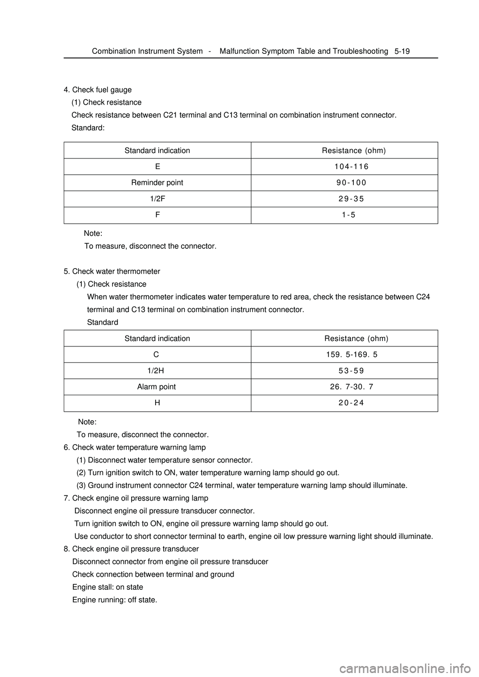
5. Check water thermometer
(1) Check resistance
When water thermometer indicates water temperature to red area, check the resistance between C24
terminal and C13 terminal on combination instrument connector.
Standard 4. Check fuel gauge
(1) Check resistance
Check resistance between C21 terminal and C13 terminal on combination instrument connector.
Standard:5-19Standard indication
E
Reminder point
1/2F
FResistance (ohm)
104-116
90-100
29-35
1-5
Standard indication
C
1/2H
Alarm point
HResistance (ohm)
159. 5-169. 5
53-59
26. 7-30. 7
20-24
Note:
To measure, disconnect the connector.
6. Check water temperature warning lamp
(1) Disconnect water temperature sensor connector.
(2) Turn ignition switch to ON, water temperature warning lamp should go out.
(3) Ground instrument connector C24 terminal, water temperature warning lamp should illuminate.
7. Check engine oil pressure warning lamp
Disconnect engine oil pressure transducer connector.
Turn ignition switch to ON, engine oil pressure warning lamp should go out.
Use conductor to short connector terminal to earth, engine oil low pressure warning light should illuminate.
8. Check engine oil pressure transducer
Disconnect connector from engine oil pressure transducer
Check connection between terminal and ground
Engine stall: on state
Engine running: off state.Combination Instrument System -Malfunction Symptom Table and Troubleshooting
Page 260 of 416
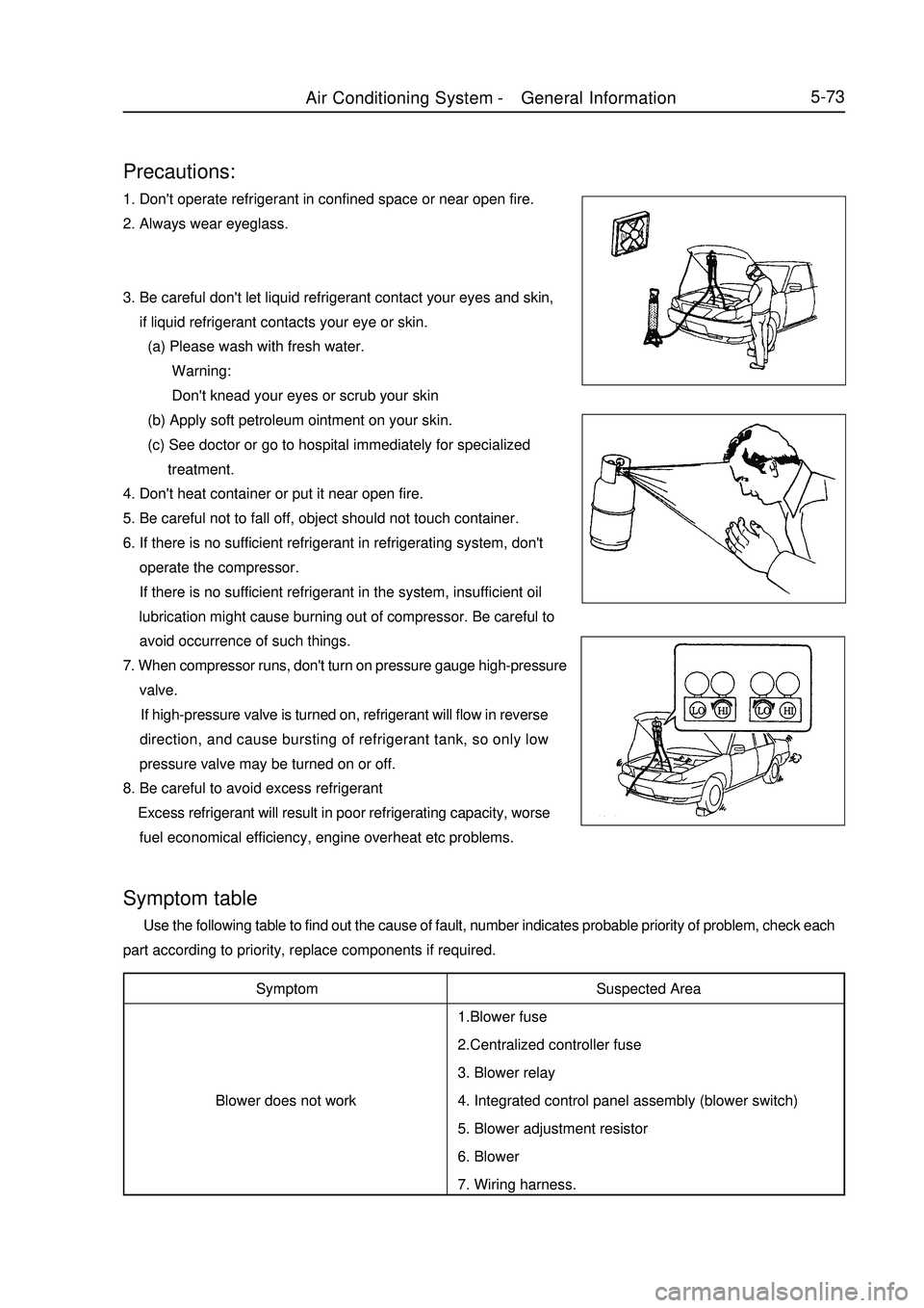
5-73Precautions:1. Don't operate refrigerant in confined space or near open fire.
2. Always wear eyeglass.
3. Be careful don't let liquid refrigerant contact your eyes and skin,
if liquid refrigerant contacts your eye or skin.
(a) Please wash with fresh water.
Warning:
Don't knead your eyes or scrub your skin
(b) Apply soft petroleum ointment on your skin.
(c) See doctor or go to hospital immediately for specialized
treatment.
4. Don't heat container or put it near open fire.
5. Be careful not to fall off, object should not touch container.
6. If there is no sufficient refrigerant in refrigerating system, don't
operate the compressor.
If there is no sufficient refrigerant in the system, insufficient oil
lubrication might cause burning out of compressor. Be careful to
avoid occurrence of such things.
7. When compressor runs, don't turn on pressure gauge high-pressure
valve.
If high-pressure valve is turned on, refrigerant will flow in reverse
direction, and cause bursting of refrigerant tank, so only low
pressure valve may be turned on or off.
8. Be careful to avoid excess refrigerant
Excess refrigerant will result in poor refrigerating capacity, worse
fuel economical efficiency, engine overheat etc problems.Symptom
Blower does not workSymptom table Use the following table to find out the cause of fault, number indicates probable priority of problem, check each
part according to priority, replace components if required.
Suspected Area
1.Blower fuse
2.Centralized controller fuse
3. Blower relay
4. Integrated control panel assembly (blower switch)
5. Blower adjustment resistor
6. Blower
7. Wiring harness.Air Conditioning System -General Information
Page 307 of 416
Fault symptom
Flameout, poor idle speedChapter 9 Engine EFI SystemI. Outline This system includes sensor that detects engine functioning. Engine ECU utilizes sensors installed at differ-
ent parts of engine to measure various working parameters of engine, accurately control oil injection quantity
according to control procedure set in engine electronic control unit, so engine could work in optimum mode
under various operating conditions, i. e. optimal power output, the most economical oil consumption, optimal
exhaust emissions. Engine ECU is capable of start up control, idle speed closed-loop control, air fuel ratio
closed-loop control, canister control, transient operation control, angle of ignition control, knocking control, air
conditioning control, coasting fuel cutoff and overspeed fuel cutoff control, ternary catalyst heating and protec-
tion control, system self-diagnosis etc.II. Inspection of control element1. Manifold intake pressure temperature sensor
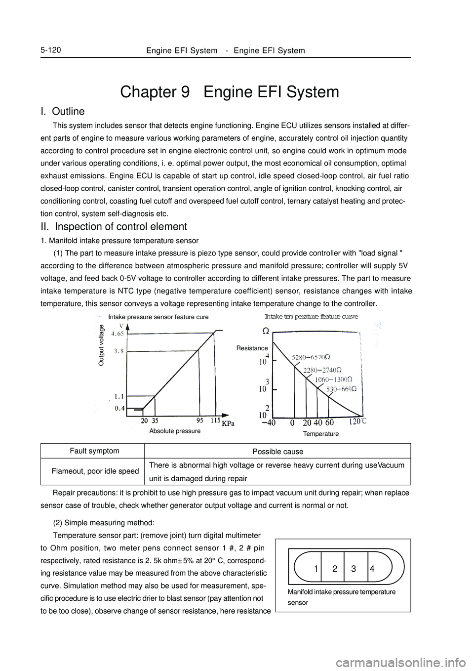
(1) The part to measure intake pressure is piezo type sensor, could provide controller with "load signal "
according to the difference between atmospheric pressure and manifold pressure; controller will supply 5V
voltage, and feed back 0-5V voltage to controller according to different intake pressures. The part to measure
intake temperature is NTC type (negative temperature coefficient) sensor, resistance changes with intake
temperature, this sensor conveys a voltage representing intake temperature change to the controller.
(2) Simple measuring method:
Temperature sensor part: (remove joint) turn digital multimeter
to Ohm position, two meter pens connect sensor 1 #, 2 # pinrespectively, rated resistance is 2. 5k ohm±5% at 20°C, correspond-ing resistance value may be measured from the above characteristic
curve. Simulation method may also be used for measurement, spe-
cific procedure is to use electric drier to blast sensor (pay attention not
to be too close), observe change of sensor resistance, here resistanceEngine EFI System-Engine EFI System5-120Possible cause
There is abnormal high voltage or reverse heavy current during useVacuum
unit is damaged during repair
Repair precautions: it is prohibit to use high pressure gas to impact vacuum unit during repair; when replace
sensor case of trouble, check whether generator output voltage and current is normal or not.1 2 3 4Manifold intake pressure temperature
sensor Intake pressure sensor feature cureIntake temperature feature curve
Output voltageAbsolute pressureTemperatureResistance
Page 311 of 416
1 2 3 45-124replacing air cleaner, always ensure that no dirt enters air duct, never
use ungraded air cleaner.
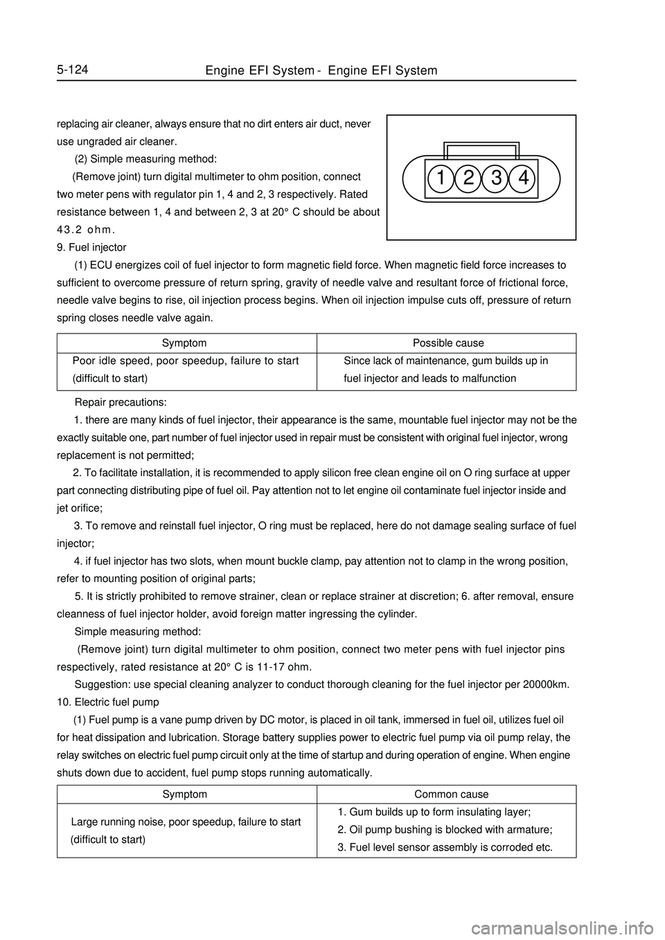
(2) Simple measuring method:
(Remove joint) turn digital multimeter to ohm position, connect
two meter pens with regulator pin 1, 4 and 2, 3 respectively. Rated
resistance between 1, 4 and between 2, 3 at 20°C should be about
43.2 ohm.
9. Fuel injector
(1) ECU energizes coil of fuel injector to form magnetic field force. When magnetic field force increases to
sufficient to overcome pressure of return spring, gravity of needle valve and resultant force of frictional force,
needle valve begins to rise, oil injection process begins. When oil injection impulse cuts off, pressure of return
spring closes needle valve again.
Symptom
Poor idle speed, poor speedup, failure to start
(difficult to start)Possible cause
Since lack of maintenance, gum builds up in
fuel injector and leads to malfunction
Repair precautions:
1. there are many kinds of fuel injector, their appearance is the same, mountable fuel injector may not be the
exactly suitable one, part number of fuel injector used in repair must be consistent with original fuel injector, wrong
replacement is not permitted;
2. To facilitate installation, it is recommended to apply silicon free clean engine oil on O ring surface at upper
part connecting distributing pipe of fuel oil. Pay attention not to let engine oil contaminate fuel injector inside and
jet orifice;
3. To remove and reinstall fuel injector, O ring must be replaced, here do not damage sealing surface of fuel
injector;
4. if fuel injector has two slots, when mount buckle clamp, pay attention not to clamp in the wrong position,
refer to mounting position of original parts;
5. It is strictly prohibited to remove strainer, clean or replace strainer at discretion; 6. after removal, ensure
cleanness of fuel injector holder, avoid foreign matter ingressing the cylinder.
Simple measuring method:
(Remove joint) turn digital multimeter to ohm position, connect two meter pens with fuel injector pins
respectively, rated resistance at 20°C is 11-17 ohm.
Suggestion: use special cleaning analyzer to conduct thorough cleaning for the fuel injector per 20000km.
10. Electric fuel pump
(1) Fuel pump is a vane pump driven by DC motor, is placed in oil tank, immersed in fuel oil, utilizes fuel oil
for heat dissipation and lubrication. Storage battery supplies power to electric fuel pump via oil pump relay, the
relay switches on electric fuel pump circuit only at the time of startup and during operation of engine. When engine
shuts down due to accident, fuel pump stops running automatically.Symptom
Large running noise, poor speedup, failure to start
(difficult to start)Common cause
1. Gum builds up to form insulating layer;
2. Oil pump bushing is blocked with armature;
3. Fuel level sensor assembly is corroded etc.Engine EFI System-Engine EFI System
Page 312 of 416

Symptom
Poor idle speed, malfunction etc
Symptom
Fail to start5-125 Repair precautions:
1. according to engine requirement, electric fuel pumps with different flows are available, they have the same
appearance, mountable fuel pump may not be exactly suitable, during repair, part number of fuel pump used must
be consistent with original one, wrong replacement is not permitted;
2. in order to prevent fuel pump from damaging, please do not run it in dry state for a long time;
3. in case fuel pump needs to be replaced, please pay attention to clean fuel tank and pipeline and replace fuel
filter.
(2) Simple measuring method:
(Remove joint) turn digital multimeter to ohm position, connect two meter pens with fuel pump pins
respectively, measure internal resistance, it should not be zero or infinite (namely not in short circuit, open circuit
condition).
(Connect joint) connect fuel pressure gauge on sucker, start up engine, run the engine at idle speed, now fuel
pressure of engine should be about 260kPa; unplug fuel pressure regulator vacuum tube, now fuel pressure should
be about 300KPa.
11. Canister control valve
(1) Canister in fuel evaporation control system adsorbs oil vapor from oil tank until saturated. Electronic
control unit controls opening of canister control valve, fresh air and saturated fuel vapor in canister form
regeneration stream, which is led into engine intake pipe again. Electronic control unit changes duty ratio of pulsing
signal to canister control valve solenoid according to different operating conditions of engine, thus controls flow
of regeneration stream. In addition, this flow is also influenced by pressure difference at both ends.
Possible cause
Entering of foreign matter into valve inside results in
corrosion or poor leak tightness etc
Repair precautions:
1. To install, airflow direction must meet the specification;
2. when black granules inside valve body result in malfunction of control valve, and control valve needs to be
replaced, please check the condition of canister;
3. avoid water, oil etc liquids from entering valve as far as possible during repair;
4. in order to avoid transfer of solid-borne noise, it is recommended to install canister control valve suspending
on the hose or use soft rubber to fix.
(2) Simple measuring method:
(Remove joint) turn digital multimeter to ohm position, connect two meter pens with canister control valve pins
respectively, rated resistance at 20°C is 22 - 30 ohm.
12. Ignition coil
(1) When earthing channel of primary winding is connected, this primary winding is charged. Once ECU cut
off primary winding circuit, charging stops, high voltage is induced in secondary winding at the same time, so spark
plug discharges. Ignition coil ZSK 22 (both ends of 2 secondary windings are connected with a spark plug
respectively, so these two spark plugs ignite simultaneously.
Possible cause
Too heavy current leads to burnout, damaged by external force Repair precautions: it is prohibited to use "short circuit ignition testing method" to test ignition function, soEngine EFI System-
Engine EFI System
Page 315 of 416

No
1
2
3
4
5
6
7
8
9
10
11
12
13
14
15
16
17
18
19
20
21
22
23
24
255-128 4. Eliminate fault code either by diagnosis instrument or manually. Manual operation method, specific
procedure: use engine data K-line (namely 9 # terminal of diagnostic interface) earth twice, earthing time is more
than 2. 5 s at each time.
Fault code tableFaulty part
No fault
Electronic control unit (unit) fault
Knocking control zero test
Knocking sensor
Storage battery voltage
Intake pressure sensor
Throttle position sensor
Idle speed control valve
Coolant temperature sensor
Intake temperature sensor
Engine maximum speed overrun
Fuel injector 1
Fuel injector 2
Fuel injector 3
Fuel injector 4
Fan relay
Oxygen sensor
Air fuel ratio control correction coefficient
? self-learning value 1
? self-learning value 2
? self-learning value 3
Fault caution light
Canister control valve
Air conditioner condenser temperature sensor
Phase sensorFault code
11
34
1
15
38
16
14
61
19
18
33
22
23
24
21
42
17
31
35
36
37
45
25
13
43Fault lamp
OFF
ON
OFF
ON
OFF
ON
ON
ON
ON
ON
OFF
ON
ON
ON
ON
ON
ON
OFF
OFF
OFF
OFF
OFF
ON
OFF
ONFault type
-
2
-
2
2
1
1
1
1
1
2
1
1
1
1
1
1
2
2
2
2
1
1
1
1
Fault type: 1-open circuit 2-signal overrun
No. 18 to 21 in the table refers to air fuel ratio correction coefficient,?=actual air quantity/air need for
combustion, "? self-learning value" is also called learning air fuel ratio control value.Engine EFI System-
Engine EFI System