check engine light GEELY MK 2008 Workshop Manual
[x] Cancel search | Manufacturer: GEELY, Model Year: 2008, Model line: MK, Model: GEELY MK 2008Pages: 416, PDF Size: 25.19 MB
Page 18 of 416
General Information - Repair Instruction1-93. Electronic Control Device
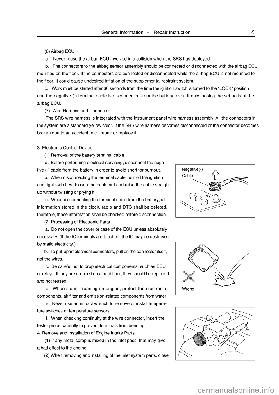
(1) Removal of the battery terminal cable
a. Before performing electrical servicing, disconnect the nega-
tive (-) cable from the battery in order to avoid short for burnout.
b. When disconnecting the terminal cable, turn off the ignition
and light switches, loosen the cable nut and raise the cable straight
up without twisting or prying it.
c. When disconnecting the terminal cable from the battery, all
information stored in the clock, radio and DTC shall be deleted,
therefore, these information shall be checked before disconnection.
(2) Processing of Electronic Parts
a. Do not open the cover or case of the ECU unless absolutely
necessary. (If the IC terminals are touched, the IC may be destroyed
by static electricity.)
b. To pull apart electrical connectors, pull on the connector itself,
not the wires.
c. Be careful not to drop electrical components, such as ECU
or relays. If they are dropped on a hard floor, they should be replaced
and not reused.
d. When steam cleaning an engine, protect the electronic
components, air filter and emission-related components from water.
e. Never use an impact wrench to remove or install tempera-
ture switches or temperature sensors.
f. When checking continuity at the wire connector, insert the
tester probe carefully to prevent terminals from bending.
4. Remove and Installation of Engine Intake Parts
(1) If any metal scrap is mixed in the inlet pass, that may give
a bad effect to the engine.
(2) When removing and installing of the inlet system parts, close (6) Airbag ECU
a. Never reuse the airbag ECU involved in a collision when the SRS has deployed.
b. The connectors to the airbag sensor assembly should be connected or disconnected with the airbag ECU
mounted on the floor. If the connectors are connected or disconnected while the airbag ECU is not mounted to
the floor, it could cause undesired inflation of the supplemental restraint system.
c. Work must be started after 60 seconds from the time the ignition switch is turned to the "LOCK" position
and the negative (-) terminal cable is disconnected from the battery, even if only loosing the set bolts of the
airbag ECU.
(7) Wire Harness and Connector
The SRS wire harness is integrated with the instrument panel wire harness assembly. All the connectors in
the system are a standard yellow color. If the SRS wire harness becomes disconnected or the connector becomes
broken due to an accident, etc., repair or replace it.Negative(-)
Cable
Wrong
Page 29 of 416
2-85. Actions to ensure vehicle working condition and safe driving.
(1) To make sure of driving safety, execute the following inspections before driving.
a. Inspect fuel level, and add fuel when necessary.
b. Inspect illuminating lights, turning signal lights, braking signal lights to see if they work.
c.Check the position of rearview mirrors.
d.Check if breaking system functions well.
e.Check if glass of all the lights, windshield is clean.
(2) Regular inspection Perform the following regular inspections to ensure the vehicle work condition and
driving safety.
a. Check engine oil level. Park the vehicle on flat road; check the oil level with engine oil level indicator
at least 10 minutes after the engine is stopped. The oil level should be between the two marks. If it is
lower than "L" mark, add some oil; if it is higher than "F" mark, there is excessive oil, so release it.
Or investigate the cause of high oil level.
The volume between the lowest oil level ("L") and highest oil level ("F") is 1.4L.
b. Check engine coolant level. Check the level when the engine is cool. The coolant level should be between
LOW and FULL. If it is lower than "LOW", add coolant. If the coolant is much lower than Min (every
coolant fill is more than 1L) or the vehicle requires frequent fills,investigate if there is any problem with
the cooling system.
To keep the function of coolant, replace coolant every two years at the beginning of cold winter.
c. Check brake and clutch fluid level (sharing a reservoir). Brake fluid level should between the Max and
Min marks. And it is better to keep it close to the Max mark. Add fluid in time when there is not enough
fluid.
d. Check power steering fluid tank. The level should be between Max and Min marks. Refill when there
is not enough steering fluid to avoid pump stuck. It is strictly prohibited to run the vehicle without
steering fluid in any circumstances.
e. Check the charging status of battery and if the connection of battery wires is good.
f. Check tire status and pressure
g. Check the status of wipers.
(3) Observe warning lights and indicators on instrument panel.
a. There are various warning lights and indicators on the instrument panel of MK-1 sedans to indicate and
warn abnormal operations of engine, braking, and charging systems.
b. Pay attention to these lights when driving.When the warning lights or indicators are on,stop the vehicle,
check the vehicle and resolve the causes to make sure the vehicle works well or drives safely.
6. Correct ways to use new cars
Reliability and stability of components in new cars and recently repaired cars still need to be confirmed, and
relative parts are not broken-in, so they must be used carefully to ensure driving safety, to avoid abnormal damage,
and to extend the useful life of the car.
(1) Before driving inspection The following inspections must be performed on the new car to ensure car safety
and reliable operation:
a. Check if instrument panel, warning lights, and indicator, front and rear wiper and washer, and switches
work.
b. Check if the fastening of driveline, steering, suspension, wheels and other connection parts is good.Usage and Maintenance of MK Series - Usage of MK Series
Page 30 of 416
2-9 c. Check levels of braking fluid, engine coolant, engine oil, transmission oil, power steering fluid, and
washing fluid to see if there is any leaking.
d. Inspect if brake pedal, clutch pedal, accelerator pedal, transmission shifter, steering wheel, choke are
loose or stuck. The free travel of clutch pedal is 5~15mm, the free travel of brake pedal is 1~6mm and
the free play of steering wheel is less than 30mm(measurement point at margin of steering wheel). if it
is out of this normal range, the clutch needs to be tuned.
e. Inspect if the connection of battery, lamps and signal lights are normal, and if the wire routing and
position are correct and not loose.
f. Inspect if the tire pressure is correct.
(2) On-road inspection If the inspection result of the above items is good, start the engine and test the car on
road, and perform the following inspections.
a. Acceleration pedal, see if the operation is smooth and if it is loose.
b. Clutch, see if there is any stuck or abnormal noise, and slip when driving.
c. Transmission,check if shifting is smooth,or rough and wrong shifting.Inspect if the display of A/T
shift lever is normal.
d. Steering, check if steering is light and smooth, and if the steering wheel turns back after steering.
e. Brake pedal, apply brake pedal to check if the braking functions well when vehicle speed is at
40km/h and if the vehicle runs off track.
f. Park brake, when parking brake handler is pulled, there should be 6~9 clicking sounds. Pull park brake
when vehicle is running at the speed of 20km/h and transmission is at neutral gear to see if it brakes.
g. Vehicle speed meter, observe the vehicle speed meter while driving. When speed changes, check if the
indicator is moving steadily or shakes.
h. Heating and air-conditioning.Try every control button to see if both heating and cooling system work
well.
i. Abnormal noise, listen carefully to see if there is any abnormal noise from engine, drive line system or
any other parts of the vehicle at a steady speed and during accelerating, and decelerating.
(3) Inspection after test ride check if there is anything abnormal in the vehicle while driving and conduct the
following inspections after the vehicle is parked.
a. Check electrical fan When engine coolant temperature is beyond 92.5°C, the radiator fan should be
running; When A/C is on and the pressure of refrigerant is more than 1.5 cooling ton, air conditioning
cooling fan should be running.
b. Check headlamp, method: park the car 5m away from the inspection surface (inspection board, curtain,
or wall) to the front bumper, and check if the beam from headlamp is good. The upper level if headlamp
should be 540mm above the ground, and the distance between headlamps on the two sides is 900mm.
c. Inspect engine idle speed,idle speed of hot engine is 800r/min±50r/min,when A/C compressor works,
the idle speed should be 900r/min±50r/min. If idle speed is abnormal, adjust the idle speed adjust
ment screw to adjust it.
(4) Usage of new cars in breaking-in period Follow the instructions below in the first 1500~2500km breaking
mileage to avoid wear and abnormal damage in breaking-in period, and to improve vehicle performance, fuel
economy and to extend vehicle useful life.
a. Drive steadily during breaking-in; do not accelerate harshly to avoid running engine at high speed.
Engine should not exceed 4500r/min in any gears. Especially at the early stage of breaking-in, vehicleUsage and Maintenance of MK Series - Usage of MK Series
Page 31 of 416
2-10 must be running at medium speed without load. Increase the speed and load gradually with the
accumulation of breaking-in mileage.
b. Because the brake plat is not broken in on a new vehicle,in order to ensure safety and reduce wear,avoid
harsh brake, and brake for multiple times to break in the brake plate faster.
c. It is better to avoid driving vehicle on steep roads or in bad conditions during breaking-in period.
d. Pay special attention to engine coolant temperature meter and oil pressure meter.Check engine oil level
frequently and make sure engine works in normal temperature and good lubrication.
e. Maintain the vehicle strictly according to first-time maintenance requirements to bring the vehicle into
normal usage life under good condition.
7.vehicle towing
There are towing facilities both in the front and rear end of MK-1 sedan for towing other vehicles and being towed.
To ensure safety, pay attention to the following instructions when towing.
(1) Towing car Towing car should be started and shifted steadily.The speed should be no more than 40km/h.
(2) Follow the instructions below when being towed:
a. Steering system of the vehicle being towed works well.
b. Braking system of the vehicle being towed works well or it cannot be towed with a rope and must be
towed with the towing shaft instead.
c. Release park brake and shift the transmission to neutral gear when the vehicle is being towed.
d. Turn the ignition switch to ACC to allow turning signal lights,braking indicator to be turned on when
necessary.
e. The towing rope must be tensioned in the towing process.
f. If the purpose of towing is to start the engine, shift the transmission to the 2nd or 3rd gear to increase
engine speed. It is good for starting the engine.
8. Instructions to save fuel when using the vehicle
(1) Reasonable load Do not store useless articles in luggage compartment because they consumes fuel for
nothing.
(2) Correct driving style Instructions as follows:
a. When engine is started, do not heat it but press the accelerator pedal slightly, drive the vehicle slowly
and accelerate gradually.
b. Shift to higher gears when driving to allow the engine to work at appropriate engine speed and avoid
running the engine at low or high speed. The engine speed should be higher than 2500r/min when
driving, and higher than 3000r/min when up-shifting.
c. Keep the vehicle speed stable, and avoid harsh acceleration and frequent braking.
d. Pay attention to vehicle speed. Drive at high speed results in excessive fuel consumption.
(3) Organize vehicle usage well Pay attention to the following two instructions.
a. Organize vehicle usage time and avoid short trips. Because at the beginning when the vehicle is started
(around 1km), the engine has not reached its efficiency point, and the fuel consumption doubles
compared to regular.
b. Select a good driving route, avoid driving through the city or blocks with heavy traffic.
(4) Keep the vehicle under good work condition Strictly follow instructions to maintain the vehicle to make
sure the vehicle is under good technical working condition, and inspect and replace key parts that affect vehicle
fuel consumptions. For example:Usage and Maintenance of MK Series - Usage of MK Series
Page 41 of 416
2-20 (3) Long time exposure to sun damages interior. So it is better to use covers on upper seat backs, and rear
separation board that are exposed to sun.
8. Maintenance of body exterior
Body exterior is to keep body cleanness and brightness to give the impression of beauty and comfort, and to avoid
rust and abnormal paint peeling off. The key points of body maintenances are:
(1) Wash body using the method below:
a. Wash the dirty things off the body by pressurized water, and then clean the body with
soft cloth of sponge from up to down.
b. Dry body surface with good white cloth. Apply brake pedal several times when driving
after the car is washed to get rid of water in braking system.
c. Do not wipe the body when it is dry. Do not clean paint surface and glass with gasoline,
coal oil, narkosid, strong lye or alcohol.
(2) Cleaning windshield glass
Do not use silicon-bronze radical products. To get better cleaning effects, use special glass cleanser.
(3) Cleaning asphalt on the body
Do not peel the asphalt off from body or bumper, but use special cleanser
(4) Paint
Scratches or slight damages can be fixed with special paint spray. It dries in the air.
(5) Cleaning exterior decoration parts and aluminum parts. Wash with water with soap fluid or cleanser, and wash with clean water. To keep the gloss of painted surface,
wax on the surface after it is dry. (6) Polish and wax the body paint polishing and waxing keeps the body bright and pretty, and protects the paint
as well.
a. Polish in winter. Make sure the vehicle body is absolutely clean and dry before
polishing, polish with fluid or milky wax.
b. Vehicle body must be absolutely dry and clean before waxing. Use waxing tools (soft
table tissue or smooth cotton cloth) to cover the body paint surface evenly with wax.
Check if the vehicle body is covered by wax: spray some water onto the paint surface,
if water drops are formed, that surface is waxed, otherwise, clean the surface and wax
it again. Attention: do not wax under sun, or in cold weather.
Attention
1) When using high pressure washing machine, do not point the washing sprayer to transmission, steering
mechanism and other rubber protection parts, or exterior decoration parts, roof welding lines, heat radiator
or engine compartment.
2) The bottom of vehicle body is made of anti-corrosion material,and has been through anti-corrosion process.
After the vehicle has been running frequently on roads de-frozen with salt for some time, clean engine
compartment and lower part of vehicle body and take some protection actions.Usage and Maintenance of MK Series - Daily Maintenance of MK Sedan
Page 43 of 416
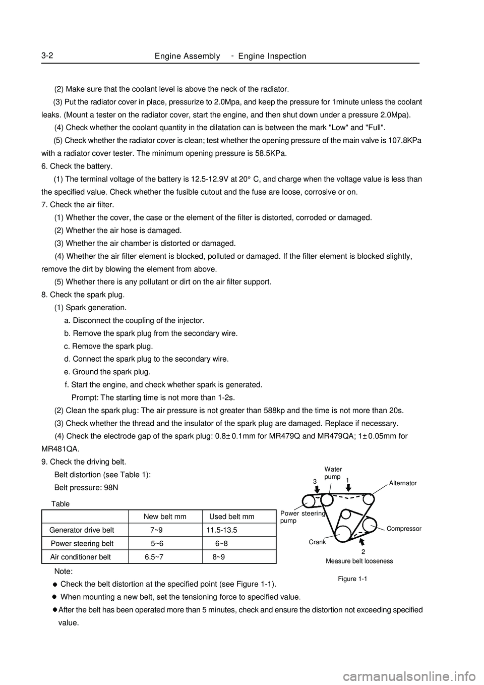
TableEngine AssemblyEngine Inspection3-2 Note:
Check the belt distortion at the specified point (see Figure 1-1).
When mounting a new belt, set the tensioning force to specified value.
After the belt has been operated more than 5 minutes, check and ensure the distortion not exceeding specified
value. (2) Make sure that the coolant level is above the neck of the radiator.
(3) Put the radiator cover in place, pressurize to 2.0Mpa, and keep the pressure for 1minute unless the coolant
leaks. (Mount a tester on the radiator cover, start the engine, and then shut down under a pressure 2.0Mpa).
(4) Check whether the coolant quantity in the dilatation can is between the mark "Low" and "Full".
(5) Check whether the radiator cover is clean; test whether the opening pressure of the main valve is 107.8KPa
with a radiator cover tester. The minimum opening pressure is 58.5KPa.
6. Check the battery.
(1) The terminal voltage of the battery is 12.5-12.9V at 20°C, and charge when the voltage value is less than
the specified value. Check whether the fusible cutout and the fuse are loose, corrosive or on.
7. Check the air filter.
(1) Whether the cover, the case or the element of the filter is distorted, corroded or damaged.
(2) Whether the air hose is damaged.
(3) Whether the air chamber is distorted or damaged.
(4) Whether the air filter element is blocked, polluted or damaged. If the filter element is blocked slightly,
remove the dirt by blowing the element from above.
(5) Whether there is any pollutant or dirt on the air filter support.
8. Check the spark plug.
(1) Spark generation.
a. Disconnect the coupling of the injector.
b. Remove the spark plug from the secondary wire.
c. Remove the spark plug.
d. Connect the spark plug to the secondary wire.
e. Ground the spark plug.
f. Start the engine, and check whether spark is generated.
Prompt: The starting time is not more than 1-2s.
(2) Clean the spark plug: The air pressure is not greater than 588kp and the time is not more than 20s.
(3) Check whether the thread and the insulator of the spark plug are damaged. Replace if necessary.
(4) Check the electrode gap of the spark plug: 0.8±0.1mm for MR479Q and MR479QA; 1±0.05mm for
MR481QA.
9. Check the driving belt.
Belt distortion (see Table 1):
Belt pressure: 98NMeasure belt loosenessCompressor
Crank Power steering
pumpWater
pump
Alternator2 1
3Figure 1-1New belt mm Used belt mm
Generator drive belt 7~9 11.5-13.5
Power steering belt 5~6 6~8
Air conditioner belt 6.5~7 8~9 -
Page 44 of 416
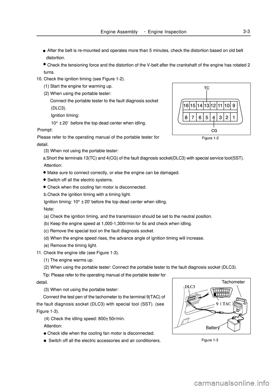
Figure 1-2
Figure 1-3Engine AssemblyEngine Inspection3-3 After the belt is re-mounted and operates more than 5 minutes, check the distortion based on old belt
distortion.
Check the tensioning force and the distortion of the V-belt after the crankshaft of the engine has rotated 2
turns.
10. Check the ignition timing (see Figure 1-2).
(1) Start the engine for warming up.
(2) When using the portable tester:
Connect the portable tester to the fault diagnosis socket
(DLC3).
Ignition timing:
before the top dead center when idling.
Prompt:
Please refer to the operating manual of the portable tester for
detail.
(3) When not using the portable tester:
a.Short the terminals 13(TC) and 4(CG) of the fault diagnosis socket(DLC3) with special service tool(SST).
Attention:
Make sure to connect correctly, or else the engine can be damaged.
Switch off all the electric systems.
Check when the cooling fan motor is disconnected.
b.Check the ignition timing with a timing light.
Ignition timing: 10°±20' before the top dead center when idling.
Note:
(a) Check the ignition timing, and the transmission should be set to the neutral position.
(b) Keep the engine speed at 1,000-1,300r/min for 5s and check when idling.
(c) Remove the special tool on the fault diagnosis socket.
(d) When the engine speed rises, the advance angle of ignition timing will increase.
(e) Remove the timing light.
11. Check the engine idle (see Figure 1-3).
(1) The engine warms up.
(2) When using the portable tester: Connect the portable tester to the fault diagnosis socket (DLC3).
Tip: Please refer to the operating manual of the portable tester for
detail.
(3) When not using the portable tester:
Connect the test pen of the tachometer to the terminal 9(TAC) of
the fault diagnosis socket (DLC3) with special tool (SST). (see
Figure 1-3).
(4) Check the idling speed: 800±50r/min.
Attention:
Check idle when the cooling fan motor is disconnected.
Switch off all the electric accessories and air conditioners.Tachometer
Battery10°±20' -
Page 191 of 416
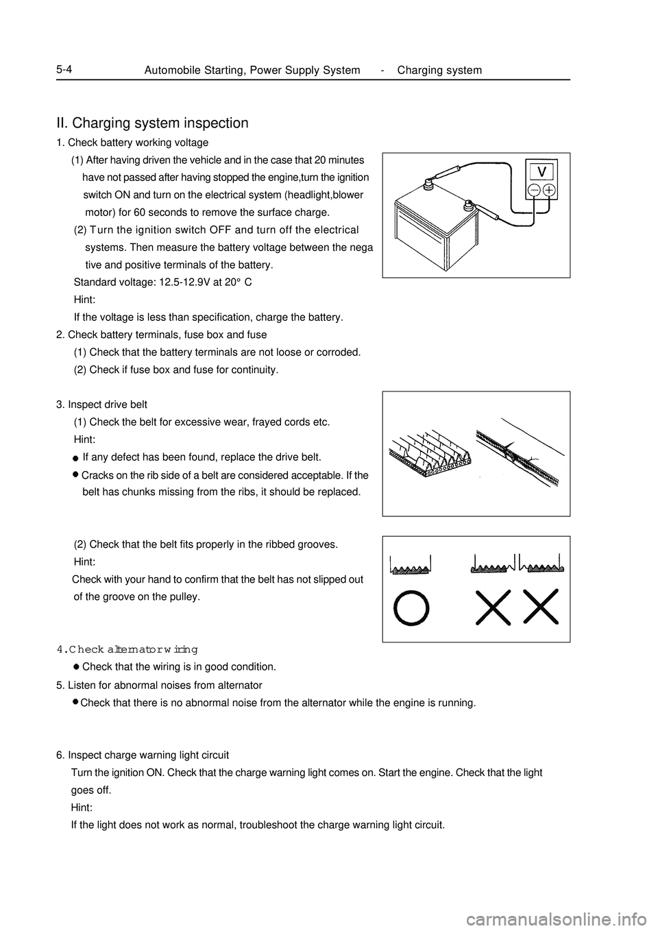
II. Charging system inspection1. Check battery working voltage
(1) After having driven the vehicle and in the case that 20 minutes
have not passed after having stopped the engine,turn the ignition
switch ON and turn on the electrical system (headlight,blower
motor) for 60 seconds to remove the surface charge.
(2) Turn the ignition switch OFF and turn off the electrical
systems. Then measure the battery voltage between the nega
tive and positive terminals of the battery.
Standard voltage: 12.5-12.9V at 20°C
Hint:
If the voltage is less than specification, charge the battery.
2. Check battery terminals, fuse box and fuse
(1) Check that the battery terminals are not loose or corroded.
(2) Check if fuse box and fuse for continuity.
3. Inspect drive belt
(1) Check the belt for excessive wear, frayed cords etc.
Hint:
If any defect has been found, replace the drive belt.
Cracks on the rib side of a belt are considered acceptable. If the
belt has chunks missing from the ribs, it should be replaced.
(2) Check that the belt fits properly in the ribbed grooves.
Hint:
Check with your hand to confirm that the belt has not slipped out
of the groove on the pulley.
4. Check alternator wiring
Check that the wiring is in good condition.Automobile Starting, Power Supply System -Charging system5-45. Listen for abnormal noises from alternator
Check that there is no abnormal noise from the alternator while the engine is running.
6. Inspect charge warning light circuit
Turn the ignition ON. Check that the charge warning light comes on. Start the engine. Check that the light
goes off.
Hint:
If the light does not work as normal, troubleshoot the charge warning light circuit.
Page 192 of 416
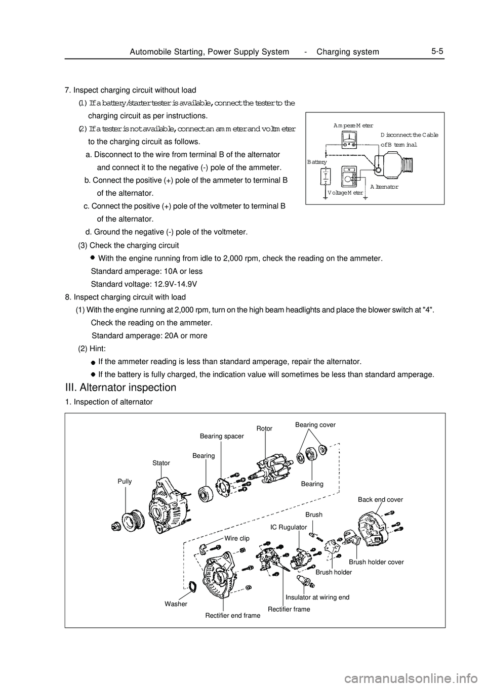
Automobile Starting, Power Supply System -Charging system5-57. Inspect charging circuit without load
(1) If a battery/starter tester is available, connect the tester to the
charging circuit as per instructions.
(2) If a tester is not available, connect an ammeter and voltmeter
to the charging circuit as follows.
a. Disconnect to the wire from terminal B of the alternator
and connect it to the negative (-) pole of the ammeter.
b. Connect the positive (+) pole of the ammeter to terminal B
of the alternator.
c. Connect the positive (+) pole of the voltmeter to terminal B
of the alternator.
d. Ground the negative (-) pole of the voltmeter.
(3) Check the charging circuit
With the engine running from idle to 2,000 rpm, check the reading on the ammeter.
Standard amperage: 10A or less
Standard voltage: 12.9V-14.9V
8. Inspect charging circuit with load
(1) With the engine running at 2,000 rpm, turn on the high beam headlights and place the blower switch at "4".
Check the reading on the ammeter.
Standard amperage: 20A or more
(2) Hint:
If the ammeter reading is less than standard amperage, repair the alternator.
If the battery is fully charged, the indication value will sometimes be less than standard amperage.III. Alternator inspection1. Inspection of alternatorPullyStatorBearingBearing spacerRotorBearing cover
Bearing
Wire clipBrush
Washer
Rectifier end frameRectifier frameInsulator at wiring endBrush holderBrush holder coverBack end coverIC RugulatorAmpere Meter
BatteryVoltage MeterAlternatorDisconnect the Cable
of B terminal
Page 197 of 416
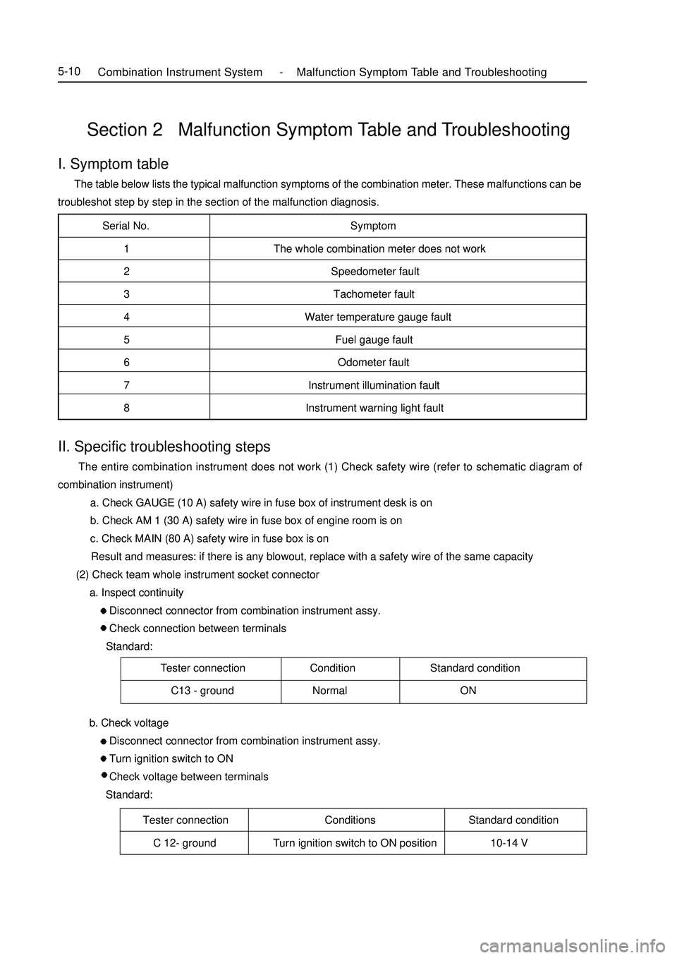
Serial No. Symptom
1 The whole combination meter does not work
2 Speedometer fault
3 Tachometer fault
4 Water temperature gauge fault
5 Fuel gauge fault
6 Odometer fault
7 Instrument illumination fault
8 Instrument warning light fault
Tester connection Condition Standard condition
C13 - ground Normal ONSection 2 Malfunction Symptom Table and TroubleshootingI. Symptom table The table below lists the typical malfunction symptoms of the combination meter. These malfunctions can be
troubleshot step by step in the section of the malfunction diagnosis.Tester connection Conditions Standard condition
C 12- ground Turn ignition switch to ON position 10-14 VCombination Instrument System -Malfunction Symptom Table and Troubleshooting5-10II. Specific troubleshooting steps The entire combination instrument does not work (1) Check safety wire (refer to schematic diagram of
combination instrument)
a. Check GAUGE (10 A) safety wire in fuse box of instrument desk is on
b. Check AM 1 (30 A) safety wire in fuse box of engine room is on
c. Check MAIN (80 A) safety wire in fuse box is on
Result and measures: if there is any blowout, replace with a safety wire of the same capacity
(2) Check team whole instrument socket connector
a. Inspect continuity
Disconnect connector from combination instrument assy.
Check connection between terminals
Standard:
b. Check voltage
Disconnect connector from combination instrument assy.
Turn ignition switch to ON
Check voltage between terminals
Standard: