radiator GEELY MK 2008 User Guide
[x] Cancel search | Manufacturer: GEELY, Model Year: 2008, Model line: MK, Model: GEELY MK 2008Pages: 416, PDF Size: 25.19 MB
Page 65 of 416

Section 2 Radiator Replacement1. Replace the radiator.
(1) Open the radiator cover.
(2) Open the water drain valve and discharge the coolant.
(3) Disconnect the water inlet pipe of the radiator.
(4) Disconnect the water outlet pipe of the radiator.
(5) Disconnect the input pipe of the oil cooler of the automatic transmission (automatic transmission).
(6) Disconnect the output pipe of the oil cooler of the automatic transmission (automatic transmission).
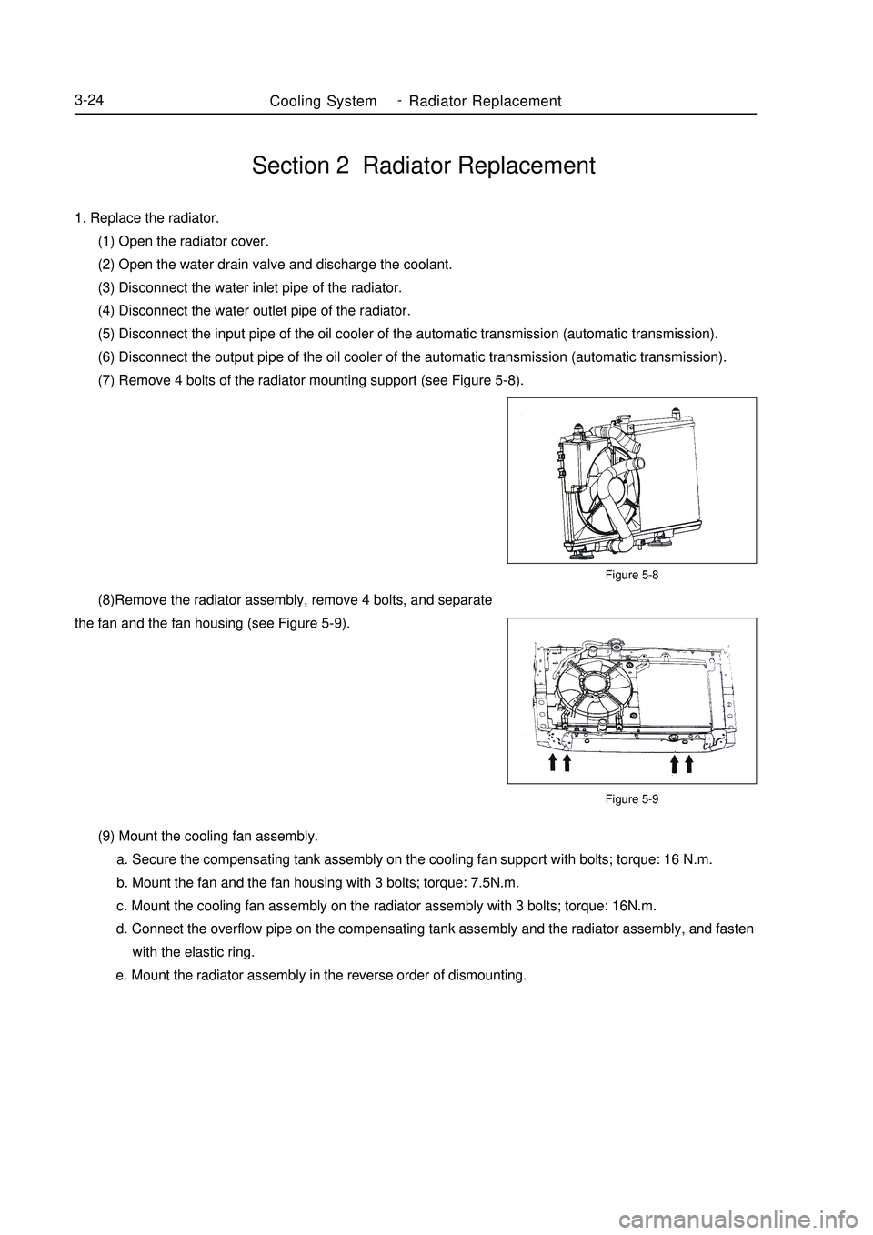
(7) Remove 4 bolts of the radiator mounting support (see Figure 5-8).Figure 5-8
Figure 5-9Cooling SystemRadiator Replacement3-24 (8)Remove the radiator assembly, remove 4 bolts, and separate
the fan and the fan housing (see Figure 5-9).
(9) Mount the cooling fan assembly.
a. Secure the compensating tank assembly on the cooling fan support with bolts; torque: 16 N.m.
b. Mount the fan and the fan housing with 3 bolts; torque: 7.5N.m.
c. Mount the cooling fan assembly on the radiator assembly with 3 bolts; torque: 16N.m.
d. Connect the overflow pipe on the compensating tank assembly and the radiator assembly, and fasten
with the elastic ring.
e. Mount the radiator assembly in the reverse order of dismounting. -
Page 267 of 416

(4) Poor refrigerant circulation1. Indicates vacuum on low pres-
sure side, indicates too low pres-
sure on high pressure side
2. There is dew or frost on pipe
before and after expansion valve
or stock solution drier1. Pressure on high, low pressure side is a bit low
2. Pipeline from stock solution drier to main set frosts
3. Refrigeration is insufficientDirt in refrigeration
drier obstructs flow
of refrigerantStock solution
drier does not
circulateReplace stock
solution drierManifold pressure gauge indication in case of poor refrigerant circulationaSystem con-
tains moisture
or dirt which
obstructs flow
of refrigerant
Expansion
valve failureRefrigerant
does not cir-
culate1. Check expansion valve
2. Use compressed air to eliminate dirt of expan-
sion valve, but it cannot be eliminated, replace
expansion valve.
3. Vacuumize and fill in appropriate quantity of
new refrigerant
4. Expansion valve leaks, replace expansion valve Manifold pressure gauge indication in case of no refrigerant circulationa (5) Refrigerant does not circulateAir Conditioning System -Refrigerant5-80Symptom Possible cause Diagnosis Correct treatment
SymptomPossible cause Diagnosis
Correct treatmentWhen there is too much refrigerant or heat dissipation of condenser is poor (6) Too much refrigerant or heat dissipation of radiator is poor
Page 268 of 416

Air Conditioning System -Refrigerant5-811. Too high pressure on the
high and low pressure side
2. Even with decreasing engine
speed, no bubble can be seen
through view glass
3. Refrigeration is insufficient1. Excessive refrigerant,
not utilizing the efficacy
of refrigerant
2. Poor heat dissipation
of condenser1.Excessive refrigerant is
circulating
2. Insufficient refrigera-
tion in condenser, block
of condenser radiator or
fan fault1. Clean condenser
2. Check operation of fan
motor
3.Check the amount of
refrigerant, and fill in proper
amount of refrigerant1. Pressure on high, low pressure side
is too high
2. Touch thesuction hose, it is hot
3. Bubble appears in glass window,
cooling is not goodThere is air in
refrigerating
system1. There is air in re-
frigerating system
2. Vacuumizing is
not complete1. Check whether compressor
lubricating oil is dirty or insuffi-
cient
2. Pump off air and fill in appro-
priate quantity of refrigerantThere is air in the system. (7) There is air in the system (8) Expansion valve fault1. Pressure on high, low pressure
side is too high
2. There is frost or a great deal of
water drops on pipeline of low
pressure sideRefrigerant in low-pres-
sure line is too much
2. Expansion valve is opened
too largeCheck expansion
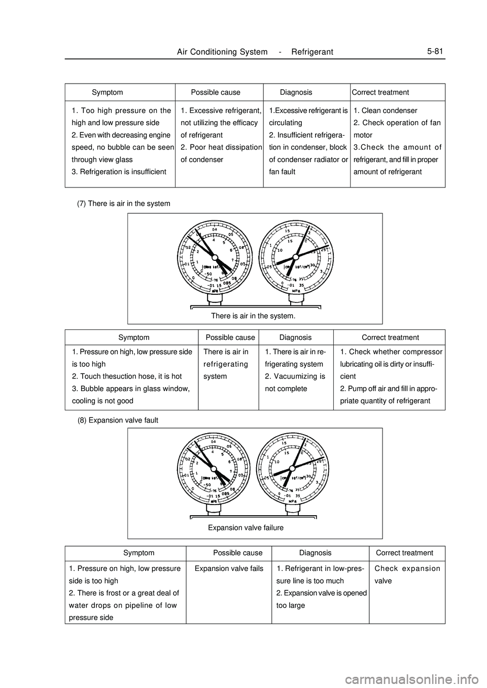
valveExpansion valve failureSymptom Possible cause Diagnosis Correct treatment
Symptom Possible cause Diagnosis Correct treatment Symptom Possible cause Diagnosis Correct treatment
Expansion valve fails1.
Page 283 of 416

Section 8 Condenser Fan Motor and Condenser AssemblyOn-board Inspection1. check condenser assembly
(1) if the radiator in the condenser is dirty, wash it with clean water and dry it with compressed air.
(2) if the radiator in the condenser is distorted, use the proper tool to correct it.
2. check the condenser for coolant leakage.
(1) use the leakage tester to check the connection area of the pipeline for leakage.
(2) If there is leakage, check the connector set bolt for tightening condition.Component Viewcondenser fan upper cushion
condenser fan
motor assembly
condenser as-
sembly
condenser lower
cushion condenser fan lower
cushioncondenser upper cushionAir Conditioning System -Condenser Fan Motor and Condenser Assembly5-96
Page 285 of 416

Air Conditioning System -Condenser Fan Motor and Condenser Assembly5-986. Remove the centor backet for the radiator.
7. Remove the condenser body.
8. Change new O sealing ring and Installation is the reverse
order of removal.
Page 362 of 416

Chapter 12 Front BumperI.Component ViewRadiator grille assemblyRight bumper bracketFront bumperRight bottom grilleFront bottom grille
Towing hitch capLeft bumper
bottom grilleLeft bumper bracketInterior & Exterior Trim and Accessory -Front Bumper6-33II. Removal and installation of front bumper Notes:
Installation is basically the reverse of removal and different operation(s) in the process of installation, if any,
will be pointed out specifically.
1. Remove the radiator grille assembly
a. Unfix 2 bolts and clips;
Page 363 of 416

Interior & Exterior Trim and Accessory -Front Bumper6-34 b. Loosen the clips by use of a screwdriver and then unfasten the radiator grille assembly.
Caution
Protect the radiator grille from damage carefully by wrapping the sharp end of screwdriver up with adhesive
tape before operation.
2. Remove the front bumper
a. Unfix 2 bolts, 6 screws and clips;
b. Loosen 2 clips and then unfasten the front bumper.
3. Remove the left bumper bracket
Unfix 2 nuts and then unfasten the bracket.
4. Remove the right bumper bracket
Unfix 2 nuts and then unfasten the bracket.
5. Remove the left bottom grille
Loosen clips and then unfasten the grille.
6. Remove the right bottom grille
Loosen clips and then unfasten the grille.
7. Remove the front bottom grille
Loosen clips and then unfasten the grille.
8. Install in reverse order of removal.
Page 373 of 416

Part VII BodyChapter 1 SurveySection 1 Body StructureThe body is made up of main structure, movable plate work, interior/exterior trim parts, and body accessories.I. Main StructureAs shown in Fig.5-1, the main structure is made up of various assemblies and parts including engine compartment
assembly & front wall parts, floor assembly, left/right wall assembly, rear wall assembly, roof assembly and
luggage compartment main cover assembly etc.Fig. 5-1 Main Structure
1 Engine compartment assembly & front wall parts 2. Left/right wall assembly
3. Luggage compartment main cover assembly 4. Rear wall assembly 5. Floor assembly
6. Roof assembly 7. Front cross beam assembly(1) Engine Compartment Assembly & Front Wall Parts The main function of the engine compartment assembly and front wall parts is to form an engine compartment
and absorb most energy generated when the vehicle is collided from the front. The compartment provides a hood
for the engine and its accessories, which can prevent the front wheel from throwing mud. In the appearance, it
represents the body's design requirements. As shown in Fig.5-2, the engine compartment assembly and front wall
parts include front cross beam assembly, left/right longitudinal beam assembly, radiator cross beam assembly,Body -Survey7-1
123456
7
Page 374 of 416

1. Front cross beam assembly
The front cross beam assembly includes front cross beam left/right support assembly, front cross beam sub-
assembly, front cross beam side support etc. They play a role in front bumper.
2. Left/right longitudinal beam assembly
The left/right longitudinal beam assembly includes left/right longitudinal bean front and mid- block assembly,
energy-absorbing beam big assembly, and left/right front damper support assembly etc.
It is mainly used to install engine left/right suspension, left/right front suspension damper, storage battery and
other accessories. In the outside, it can be equipped with left/right front fender.
3. Radiator cross beam assembly
The radiator cross beam assembly includes radiator left/right post big assembly, radiator lower cross beam big
assembly, radiator central support sub-assembly, and radiator upper cross beam big assembly etc.
It is mainly used to install radiator, condenser, engine hood lock, radiator hood, front bumper, and front
headlight.
4. Front wall lower plate assembly
The front wall lower plate connects to the floor, which separates the engine compartment from the cabin. It
includes front wall frame assembly, front wall lower main plate assembly, brake installation reinforced plate, and
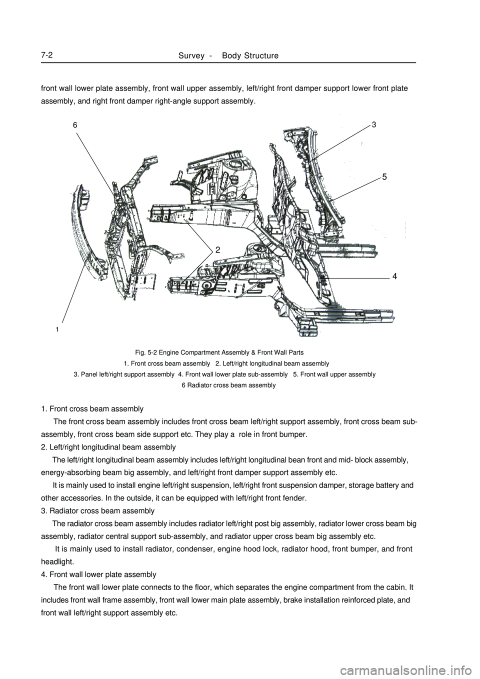
front wall left/right support assembly etc.Fig. 5-2 Engine Compartment Assembly & Front Wall Parts
1. Front cross beam assembly 2. Left/right longitudinal beam assembly
3. Panel left/right support assembly 4. Front wall lower plate sub-assembly 5. Front wall upper assembly
6 Radiator cross beam assemblySurvey -Body Structure7-2123456front wall lower plate assembly, front wall upper assembly, left/right front damper support lower front plate
assembly, and right front damper right-angle support assembly.
Page 407 of 416

7-35Section 5 Painting Techniques After Body RepairIn the practical use, various factors may cause painting damage, such as traffic accident, component rust,
premature damage due to bubble, and local color change etc. It is necessary to make repair locally as the following
steps:I. Base Processing (Pretreatment)1. Remove the paint, and remove the coating on the plate work.
2. Cut the edges and corners, and polish the metal plate without paint and the uneven paint at the edge.
3. Blow and clean the dust and dirt, and remove the grease with degreasant.II. Primer Processing1. Apply the self-drying primer on the bare metal surface.
2. Leave the primer drying naturally, or dry it with the infrared radiator.
3. Apply the self-drying oily putty or polyester putty on the plate work surface.
4. Leave the putty drying naturally or artificially.
5. Polish the putty manually to remove the uneven parts.
6. Polish it manually in water to clear the sandpaper lines.
7. Wash the dirt, polish the oil dirt and putty slurry.
8. Wipe the oil dirt on the polishing surface.
9. Cover the part not to be repaired with protective shield or paper.III. Painting Intermediate Coat1. Paint the second primer.
2. Leave the primer drying naturally or dry it.
3. Find out the sand hole or sandpaper line.
4. Polish it manually in wet condition.
5. Wash the part clean, and leave it drying naturally. (The number of putty applying and polishing depends on the
evenness of the surface to be repaired.)IV. Preparing to Paint Surface Paint1. Paste paper on the surface not to be painted.
2. Remove the dust and grease on the local surface paint.
3. Mix the color the same with that of the vehicle's surface paint.
4. Prepare the paint.V. Painting Surface Paint1. Paint the part with fast-drying surface paint 3-4 times and synthetic resin paint 2-3 times.
2. Leave it drying naturally or dry it.VI. Polishing1. After painting, burnish the part with wax to clear the shadow and improve the effect.
2. After painting, tear off the paper and wipe the ground paint.
3. Check the appearance and quality.Body Repair -Painting Techniques After Body Repair