sensor GEELY MK 2008 User Guide
[x] Cancel search | Manufacturer: GEELY, Model Year: 2008, Model line: MK, Model: GEELY MK 2008Pages: 416, PDF Size: 25.19 MB
Page 58 of 416
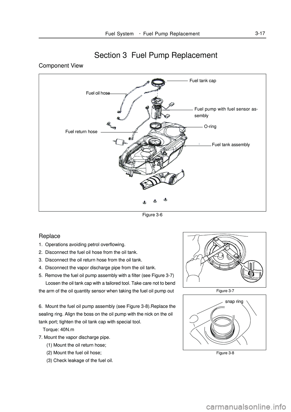
Section 3 Fuel Pump ReplacementComponent ViewFigure 3-6Replace1. Operations avoiding petrol overflowing.
2. Disconnect the fuel oil hose from the oil tank.
3. Disconnect the oil return hose from the oil tank.
4. Disconnect the vapor discharge pipe from the oil tank.
5. Remove the fuel oil pump assembly with a filter (see Figure 3-7)
Loosen the oil tank cap with a tailored tool. Take care not to bend
the arm of the oil quantity sensor when taking the fuel oil pump out
6. Mount the fuel oil pump assembly (see Figure 3-8).Replace the
sealing ring. Align the boss on the oil pump with the nick on the oil
tank port; tighten the oil tank cap with special tool.
Torque: 40N.m
7. Mount the vapor discharge pipe.
(1) Mount the oil return hose;
(2) Mount the fuel oil hose;
(3) Check leakage of the fuel oil.Figure 3-7
Figure 3-8Fuel SystemFuel Pump Replacement3-17Fuel tank cap
Fuel pump with fuel sensor as-
sembly
O-ring
Fuel tank assembly Fuel return hoseFuel oil hose
snap ring -
Page 64 of 416

Figure 5-6
Figure 5-7Above 93°CFigure 5-5Cooling SystemSystem Inspection3-235. Fan
(1) At low temperature (lower than 83°C), check the operation of
the cooling fan.
a. The ignition switch is set to ON.
b. The cooling fan should stop.
c. Disconnect the connector of the water temperature sensor.
(see Figure 5-5)
d.Touch the ground with a wire.
e.Check if the cooling fan rotates.
f. Re-connect the connector of the water temperature sensor.
(2) At high temperature (more than 93°C), check the operation of
the fan (see Figure 5-6).
a. Start the engine, and enable the coolant temperature higher
than 93°C.
b.Check whether the cooling fan rotates.
If not, replace the water temperature switch.
(3) Check the cooling fan (see Figure 5-7).
a. Disconnect the joint of the cooling fan.
b. Connect the battery and the ammeter with the connector.
c. The cooling fan should rotate stably and check the current
readings.
Standard current: 5.7-7.7A.
d. Connect the connector of the cooling fan.disconnectBattery Amper meter -
Page 66 of 416
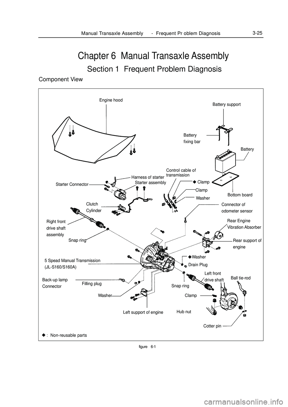
Chapter 6 Manual Transaxle AssemblySection 1 Frequent Problem DiagnosisComponent Viewfigure6-1Manual Transaxle Assembly Frequent Pr oblem Diagnosis3-25Battery support
Battery
fixing bar
Bottom board
Rear Engine
Vibration Absorber Starter assembly Engine hood
Control cable of
transmissionBattery
Harness of starter
Clamp
Clamp
Washer
Connector of
odometer sensor Clutch
Cylinder Starter Connector
Rear support of
engine
5 Spead Manual Transmission
(JL-S160/S160A)
Left front
drive shaftBall tie-rod
Cotter pin Hub nut Snap ring
Clamp
Left support of engineWasher
Washer Back-up lamp
ConnectorFilling plugDrain Plug Right front
drive shaft
assembly
Snap ring: Non-reusable parts -
Page 67 of 416

Table 6-1 Frequent problem diagnosisPossible causes
Transmission or the engine is suspended loosely or damaged;
Axial gap is improper;
Gear or bearing is worn or damaged;
Unsatisfactory transmission oil is used or oil level is low;
Engine idle is incorrect.
The oil seal or the O-ring is damaged.
The control cable is unqualified;
Synchronizer is poorly contacted with gear or worn;
Elasticity of the synchronous spring is insufficient;
Unqualified transmission oil is used.
Fork of the shift gear is worn or lifting spring is broken;
Gap between the synchronizer bush and the sleeve spline is too large;
Gear or bearing is worn or damaged. Sympton
Vibration and noise
Oil leakage of the transmission
Hard to shift
Trip stopManual Transaxle Assembly Vehicle Speed Sensor Replacement3-261. Disengage the vehicle speed sensor (see Figure 6-2).
2. Remove the bolt and the vehicle speed sensor.
3. Mount the vehicle speed sensor (see Figure 6-3).
4. Connect the vehicle speed sensor.Section 2 Vehicle Speed Sensor ReplacementFigure 6-2
Figure 6-3 -
Page 68 of 416
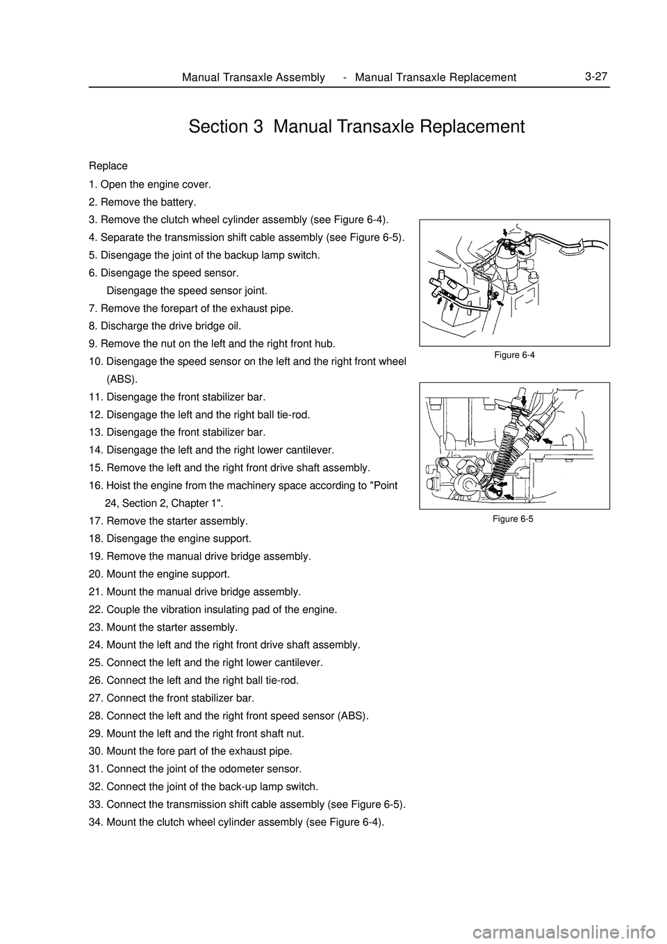
Figure 6-5Manual Transaxle Assembly Manual Transaxle Replacement3-27Section 3 Manual Transaxle ReplacementReplace1. Open the engine cover.
2. Remove the battery.
3. Remove the clutch wheel cylinder assembly (see Figure 6-4).
4. Separate the transmission shift cable assembly (see Figure 6-5).
5. Disengage the joint of the backup lamp switch.
6. Disengage the speed sensor.
Disengage the speed sensor joint.
7. Remove the forepart of the exhaust pipe.
8. Discharge the drive bridge oil.
9. Remove the nut on the left and the right front hub.
10. Disengage the speed sensor on the left and the right front wheel
(ABS).
11. Disengage the front stabilizer bar.
12. Disengage the left and the right ball tie-rod.
13. Disengage the front stabilizer bar.
14. Disengage the left and the right lower cantilever.
15. Remove the left and the right front drive shaft assembly.
16. Hoist the engine from the machinery space according to "Point
24, Section 2, Chapter 1".
17. Remove the starter assembly.
18. Disengage the engine support.
19. Remove the manual drive bridge assembly.
20. Mount the engine support.
21. Mount the manual drive bridge assembly.
22. Couple the vibration insulating pad of the engine.
23. Mount the starter assembly.
24. Mount the left and the right front drive shaft assembly.
25. Connect the left and the right lower cantilever.
26. Connect the left and the right ball tie-rod.
27. Connect the front stabilizer bar.
28. Connect the left and the right front speed sensor (ABS).
29. Mount the left and the right front shaft nut.
30. Mount the fore part of the exhaust pipe.
31. Connect the joint of the odometer sensor.
32. Connect the joint of the back-up lamp switch.
33. Connect the transmission shift cable assembly (see Figure 6-5).
34. Mount the clutch wheel cylinder assembly (see Figure 6-4).Figure 6-4 -
Page 71 of 416
The valve body fails.
12. The vehicle shifts before or after some gear points in the running status.
The vehicle switch or parking switch fails.
13. The vehicle has poor acceleration in running.
(1)The clutch or brake fails.
(2)The engine system fails.
14. The vehicle vibrates when it runs at a constant speed or accelerating speed.
(1)The hydraulic torque clutch pressure or hydraulic torque meter fails.
(2)The engine system or valve fails.
15. The acceleration switch system fails.
(1)The acceleration switch or ignition switch fails.
(2)The connector or automatic transmission control unit fails.I. Automatic transmissions Removal1. Put the select lever in "N" position
2. Remove 3 bolts of the flexibility plate (engine side)
3. Remove starter and 2 cooling hoses.
4. Disconnect neutral switch connector and odometer sensor.
5. Loosen the drain screw under the housing to bleed ATF and tighten the drain screw with sealing glue when
assembling. Tightening torque is 29~35N.m
6. Loosen the locking bolt for select lever cable.
7. Remove Drive Shaft LH&RH, using plastic stopper in the oil sealing of differential.
8. Detach suspension bolts.
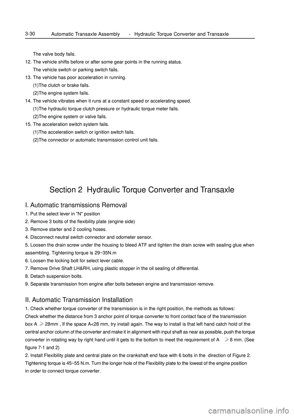
9. Separate transmission from engine after bolts between engine and transmission remove.II. Automatic Transmission Installation1. Check whether torque converter of the transmission is in the right position, the methods as follows:
Check whether the distance from 3 anchor point of torque converter to front contact face of the transmission
box A 28mm , If the space A<28 mm, try install again. The way to install is that left hand catch hold of the
central anchor column of the converter and make it in alignment with input shaft as near as possible, push the torque
converter in rotating way by right hand until it gets to the bottom to meet the requirement of A 28 mm. (See
figure 7-1 and 2)
2. Install Flexibility plate and central plate on the crankshaft end face with 6 bolts in the direction of Figure 2.
Tightening torque is 45~55 N.m. Turn the longer hole of the Flexibility plate to the lowest of the engine position
in order to connect torque converter.Section 2 Hydraulic Torque Converter and TransaxleAutomatic Transaxle Assembly Hydraulic Torque Converter and Transaxle3-30 -
Page 73 of 416
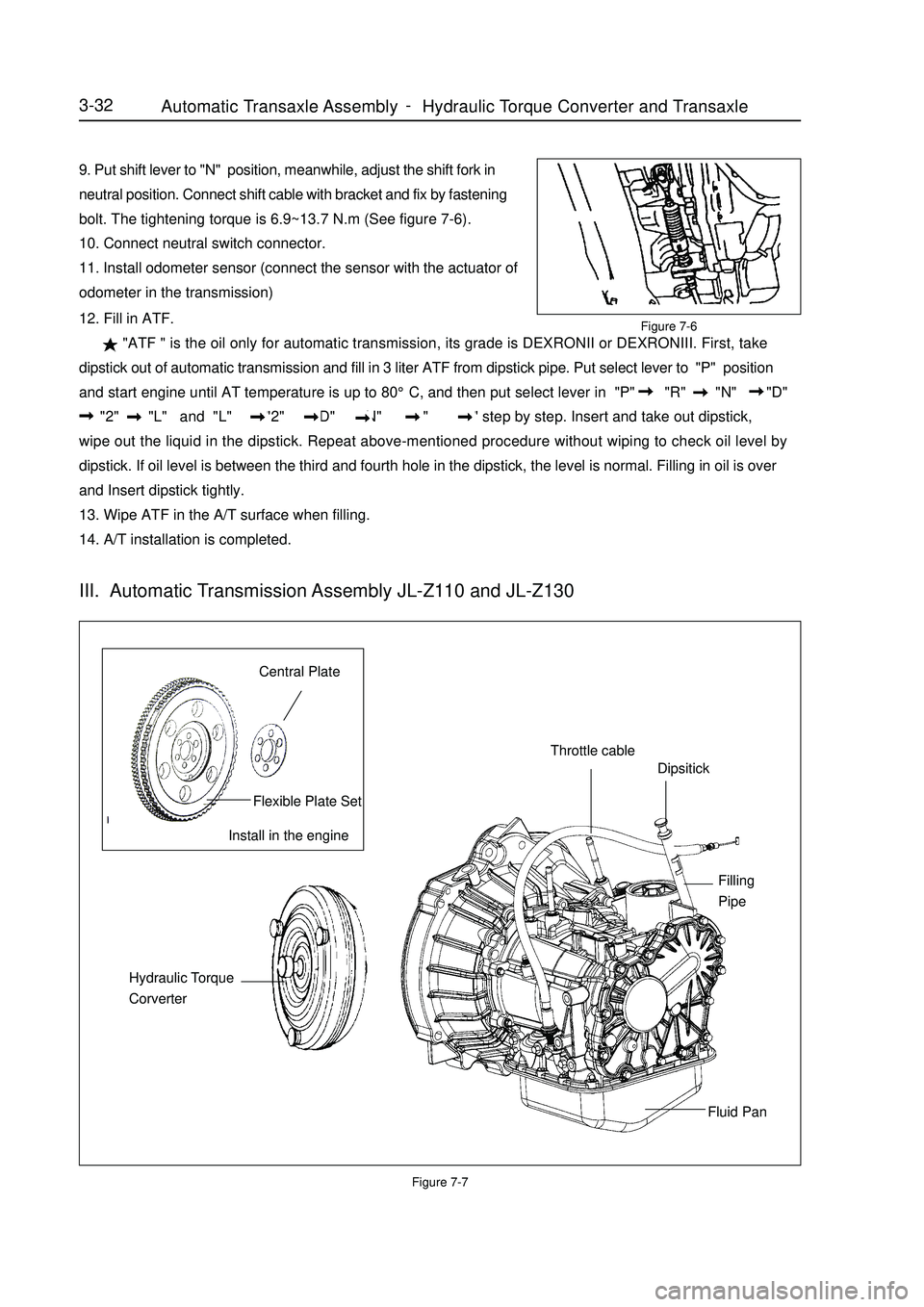
9. Put shift lever to "N" position, meanwhile, adjust the shift fork in
neutral position. Connect shift cable with bracket and fix by fastening
bolt. The tightening torque is 6.9~13.7 N.m (See figure 7-6).
10. Connect neutral switch connector.
11. Install odometer sensor (connect the sensor with the actuator of
odometer in the transmission)Figure 7-712. Fill in ATF.
"ATF " is the oil only for automatic transmission, its grade is DEXRONII or DEXRONIII. First, take
dipstick out of automatic transmission and fill in 3 liter ATF from dipstick pipe. Put select lever to "P" position
and start engine until AT temperature is up to 80°C, and then put select lever in "P" "R" "N" "D"
"2" "L" and "L" "2" "D" "N" "R" "P" step by step. Insert and take out dipstick,
wipe out the liquid in the dipstick. Repeat above-mentioned procedure without wiping to check oil level by
dipstick. If oil level is between the third and fourth hole in the dipstick, the level is normal. Filling in oil is over
and Insert dipstick tightly.
13. Wipe ATF in the A/T surface when filling.
14. A/T installation is completed.3-32Install in the engineCentral PlateFlexible Plate SetThrottle cableDipsitickFilling
PipeFluid Pan Hydraulic Torque
CorverterIII. Automatic Transmission Assembly JL-Z110 and JL-Z130Figure 7-6Automatic Transaxle Assembly Hydraulic Torque Converter and Transaxle -
Page 96 of 416

Section 2 Front DriveshaftComponent Viewsnap ring
snap ring
set nutPropeller Shaft/DriveshaftFront Driveshaft4-19right constant velocity drive
shaft assembly
right constant velocity drive
shaft assembly
Tie rod left end assembly
cotter pin
left lower swing arm collar gasket collar
gasket with ABS LF vehicle speed sensor
brake hose
front stabilizer bar
cotter pin
specified torqueN.
m :
Non-reusable parts -
Page 98 of 416

Overhaul1. Drain manual transmission oil (M/T transmission)
Torque: 39N.m
2. Drain automatic transmission oil (A/T transmission)
Torque: 25N.m
3. Remove front wheel
4. Remove engine bottom left shield (M/T transaxle)
5. Remove engine bottom right shield (M/T transaxle)
6. Remove engine bottom shield assembly (A/T transaxle)
7. Remove front wheel hub left bolt
(1) Using a hammer and a drive shaft nut chisel, unstake the
staked part of the left wheel hub nut.
(2) While applying the brake pedal, remove the left wheel hub
nut.
Notice: the staked part of the nut should be fully unstaked,
otherwise it may damage the thread of the drive shaft.
8. Remove left front vehicle speed sensor (with ABS)
(1) Remove the bolt and clip, remove vehicle speed sensor and
brake hose from left front shock absorber assembly.
(2) Remove the bolt, separate the left front vehicle speed sensor
from steering knuckle.
9. Remove front stabilizer bar
(1) Use a 10mm wrench to hold the bolt, remove the nut
(2) Remove two collars, No.1 and No.2 gaskets, remove front
stabilizer barPropeller Shaft/DriveshaftFront Driveshaft4-21 -
Page 99 of 416

10. Separate left lower swing arm assembly
(1) Remove cotter pin and nut
(2) On steering knuckle, remove the left lower swing arm
assembly with ball joint puller.
11. Separate steering gear with tie rod assembly
(1) Remove cotter pin and nut
(2) On steering knuckle, remove the steering gear with tie rod
assembly with ball joint puller.Propeller Shaft/DriveshaftFront Driveshaft4-2212. Separate LF steering knuckle assembly
Using a plastic hamper, separate left front drive shaft assembly from left front steering knuckle assembly
Notice:
Do not damage the boot.
With ABS:
Be careful not to damage the vehicle speed sensor rotor.
13. Remove left constant velocity drive shaft assembly
Using a differential side gear shaft remover, remove the left
constant velocity drive shaft assembly.
Notice:
Do not damage the boot and oil seal.
Be careful not to drop the drive shaft assembly.
14. Remove right constant velocity drive shaft assembly
Using a brass bar and a hammer, remove the right constant
velocity drive shaft assembly.
Notice:
Do not damage the boot and oil seal.
Be careful not to drop the drive shaft assembly. -