ECU GEELY MK 2008 Owner's Manual
[x] Cancel search | Manufacturer: GEELY, Model Year: 2008, Model line: MK, Model: GEELY MK 2008Pages: 416, PDF Size: 25.19 MB
Page 248 of 416

(21) Airbag ECU warning light is short to power supply (DTC 93D5)
When using the scan tool to test the airbag ECU, the DTC is 93D5, indicating that the airbag ECU warning
light is short to power supply.5-61 (16) The passenger side pretensioner seat belt resistance is too high (DTC 93D0)
When using the scan tool to test the airbag ECU, the DTC is 93D0, indicating that the passenger side
pretensioner seat belt resistance is too high, the resistance is higher than 4.5 ohm.
(17) The passenger side pretensioner seat belt resistance is too low (DTC 93D1)
When using the scan tool to test the airbag ECU, the DTC is 93D1, indicating that the passenger side
pretensioner seat belt resistance is too low, the resistance is lower than 1.2 ohm.
(18) The passenger side pretensioner seat belt resistance is short to ground (DTC 93D2)
When using the scan tool to test the airbag ECU, the DTC is 93D2, indicating that the passenger side
pretensioner seat belt is short to ground, the resistance is lower than 6.5K ohm.
(19) The passenger side pretensioner seat belt resistance is short to power supply (DTC 93D3)
When using the scan tool to test the airbag ECU, the DTC is 93D3, indicating that the passenger side
pretensioner seat belt is short to power supply, the resistance is lower than 21K ohm.
(20) Airbag ECU warning light is short to ground or warning light wire harness is disconnected (DTC 93D4)
When using the scan tool to test the airbag ECU, the DTC is 93D4, indicating that the airbag ECU warning light
is short to ground or the warning light wire harness is disconnected.
Step Operation Yes No
1 When using the scan tool to test the airbag ECU, is the DTC 93D5? Go to step 2 other
2 Go to step 3 Go to step 5
3 Go to step 4 Go to step 5
4 Check the LED and wire harness for connection. Go to step 5
5 Go to step 6 Go to step 1
6 The fault has been removed, use the scan tool to eliminate the DTC.Shut off the power supply, check whether the airbag ECU wire harness
connection is ok? (is there any short)
Check the connector of the warning light on airbag ECU wire harness (is
there any short)?
After the troubleshooting, switch on the power supply, observe the status
of the warning light. The warning light shall goes off after lighting up for
4 seconds (self-check).Step Operation Yes No
1 When using the scan tool to test the airbag ECU, is the DTC 93D4? Go to step 2 other
2 Go to step 3 Go to step 5
3 Go to step 4 Go to step 5
4 Check the LED and wire harness for connection. Go to step 5
5 Go to step 6 Go to step 1
6 The fault has been removed, use the scan tool to eliminate the DTC.Shut off the power supply, check whether the airbag ECU wire harness
connection is ok? (is there any short)Check the connector of the warning light on airbag ECU wire harness (is there any short)?After the troubleshooting, switch on the power supply, observe the status
of the warning light. The warning light shall goes off after lighting up for
4 seconds (self-check).SRS (Supplemental Restraint System)-SRS-General Information
Page 249 of 416

5-62 (22) There are problems in the configuration of the airbag ECU (DTC 93D6)
When using the scan tool to test the airbag ECU, the DTC is 93D6, indicating that there are problems in the
configuration of the airbag ECU.
Step Operation Yes No
1 When using the scan tool to test the airbag ECU, is the DTC 93D6? Go to step 2 other
2Go to step 3
3 Go to step 4 Go to step 1
4 The fault has been removed, use the scan tool to eliminate the DTC.Check whether the configuration of the airbag ECU is consistent with the
actual on-board configuration?
After the troubleshooting, switch on the power supply, observe the status
of the warning light. The warning light shall goes off after lighting up for
4 seconds (self-check). (23) The impact signal output interface of the airbag ECU is short to ground or the impact output circuit is
disconnected. (DTC 93D7)
When using the scan tool to test the airbag ECU, the DTC is 93D7, indicating that the impact signal output
interface of the airbag ECU is short to ground or the impact output circuit is disconnected.IV. Diagnosis of collided vehicle No matter airbag is unfolded or folded, inspection and maintenance of collided vehicle should be performed
according to the following sequence.
1. Check ECU diagnosis signal.
(1) Connect scanner diagnosis joint
(2) Use scanner to read out diagnosis result.
2. Repair sequence
(1) when airbag is unfolded.
The following components should be replaced with new parts
a. Airbag assembly on passenger side
b. ECU
c. Airbag assembly on driver side
d. Seat belt with pretensionerNote:
due to impact, when battery power is insufficient, scanner can not communicate with ECU, now check and
service instrument board wire harness or use external power supply.SRS (Supplemental Restraint System)-SRS-General Information (2 ) Check the following components, if there is any abnormity, replace with new parts
a. Clock spring.
b. Steering wheel, steering column, lower steering shaft assembly
(3 ) The installation status of driver airbag assembly in relation to steering wheel
a. Check and see if there is abnormal noise in the steering wheel, the action of the same is good, or the
clearance is normal.
b. Check the connecter of the wire harness for damage and the terminal for distortion.
Page 250 of 416

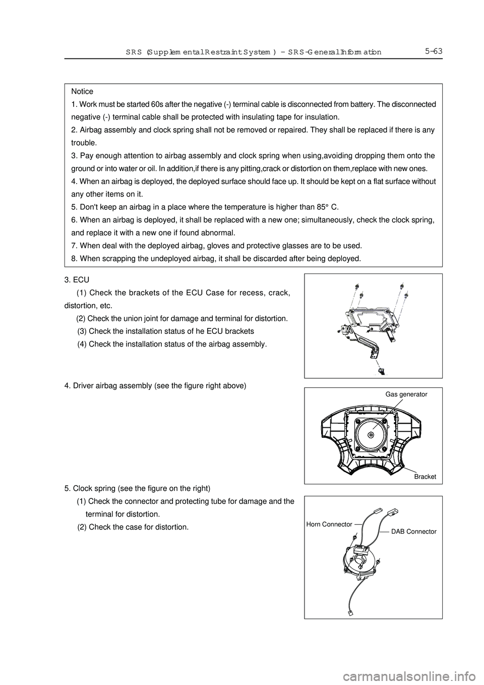
5-633. ECU
(1) Check the brackets of the ECU Case for recess, crack,
distortion, etc.
(2) Check the union joint for damage and terminal for distortion.
(3) Check the installation status of he ECU brackets
(4) Check the installation status of the airbag assembly.Notice
1. Work must be started 60s after the negative (-) terminal cable is disconnected from battery. The disconnected
negative (-) terminal cable shall be protected with insulating tape for insulation.
2. Airbag assembly and clock spring shall not be removed or repaired. They shall be replaced if there is any
trouble.
3. Pay enough attention to airbag assembly and clock spring when using,avoiding dropping them onto the
ground or into water or oil. In addition,if there is any pitting,crack or distortion on them,replace with new ones.
4. When an airbag is deployed, the deployed surface should face up. It should be kept on a flat surface without
any other items on it.
5. Don't keep an airbag in a place where the temperature is higher than 85°C.
6. When an airbag is deployed, it shall be replaced with a new one; simultaneously, check the clock spring,
and replace it with a new one if found abnormal.
7. When deal with the deployed airbag, gloves and protective glasses are to be used.
8. When scrapping the undeployed airbag, it shall be discarded after being deployed.Bracket Gas generatorDAB ConnectorHorn ConnectorSRS (Supplemental Restraint System)-SRS-General Information4. Driver airbag assembly (see the figure right above)
5. Clock spring (see the figure on the right)
(1) Check the connector and protecting tube for damage and the
terminal for distortion.
(2) Check the case for distortion.
Page 251 of 416

6. Steering wheel, steering column and steering lower shaft component.
(1) Check the installation status of driver airbag assembly.
(2) Check the steering wheel for any abnormal noise and see if the clearance is normal.
7. Check the wire harness connector (instrument panel wire harness).
Check and see if the wire harness is securely installed, if the joint is damaged and if the terminal is distorted.V. Warning marks When using or maintaining an airbag, the warnings shall be indicated. When maintaining, proceed in
accordance with the description of mark. In addition, if the mark is damaged or stained, it shall be replaced.
(1) Steering wheel, see Fig. 1.
(2) Driver airbag assembly, see Fig. 2.
(3) Clock spring, see Fig. 3.
Fig. 1.Fig. 2.Warning markFig. 3.Warning
mark (4) ECU, see Fig. 4.
(5) Sunshade, see Fig. 5.VI. SRS electronic control unit (ECU)Removal and Installation
1. Operations prior to Removal
(1) Turn the ignition switch OFF.
(2) Remove negative (-) terminal cable of the battery. Put it in a proper position or wrap it up with insulating
tape.Fig. 4.Fig. 5.5-64SunshadeSRS (Supplemental Restraint System)-SRS-General Information
Page 252 of 416

Notice
1. Work must be started 60s after the negative (-) terminal cable is detached from battery. The detached
negative (-) terminal cable shall be protected with insulating tape for insulation.
2. Never attempt to dismantle or repair an ECU. If there is any trouble, replace the ECU with a new one.
3. Prevent the ECU from shock or vibration. If pitting, crack or distortion is found, replace the ECU with a
new one.
4. Every time an airbag is deployed, the ECU shall be replaced with a new one.
5. When disassembling or maintaining the parts around ECU, attention must be given to avoid contacting the
ECU. 2. Removal procedures:
(1) Remove the miscellaneous box in the middle consoce.
(2) Remove the connectors to SRS ECU.
(3) Remove ECU.
3. Installation procedures:
(1) Install ECU.
(2) Install the connectors to SRS ECU.
(3) Install the miscellaneous box in the middle consoce.
(4) Connect negative (-) terminal cable of the battery.
4. Key points for Installation:
(1) Install ECU.Notice
If the ECU cannot be installed correctly, the airbag will not act normally.
5. Check
a. ECU case for pitting, crack and distortion
b. The connector for damage and distortion.Notice
If pitting, crack or distortion is found on an ECU, replace it with a new one.VII. Airbag assembly & clock spring1.Removal and Installation of driver airbag and clock spring
Operations prior to removal
(1)Take out the ignition key after the steering wheel and front
wheel are adjusted to straightforward direction.
(2)Remove negative (-) terminal cable from the battery.
Removal procedures of the driver airbag assembly:
(1) Unscrew the screws of the two sides, see fig.15-65SRS (Supplemental Restraint System)-SRS-General Information (2) Check after installation.
a. Turn the ignition switch ON.
b. The warning light goes on within 4s, and then goes out.
(3) If the light doesn't go out, check the trouble and eliminate it.
For other ECU inspections, see Troubleshooting.
fig.1
Page 257 of 416

1) Disconnect the positive (+) and negative (-) terminal cables from the battery and remove the battery from
the vehicle.Notice
Work must be started 60s after removal of the battery.Notice
When the connector is not connected, the terminals of the driver airbag assembly will be short circuited
automatically, preventing the airbag from being deployed unexpectedly. If the airbag is deployed unexpectedly,
the deployed surface should face up. It should be kept on a flat surface without any other items on it. 2) The airbag assembly shall be deployed according to the following procedures.
Driver airbag assembly
a. Remove the driver airbag assembly from the vehicle.
b. Prepare two 6m plus wire harnesses for deployment, connect
the other two ends to avoid unexpected deployment in case
of static electricity (see the figure below).Notice
The above-mentioned procedures can prevent the unexpected deployment due to static electricity and shall
therefore be performed strictly.Deployed Harness
Short Circuit Point
More than 6mInsulation tapeDeployment
wire harness
Short circuit
locationDriverÕs airbag
moduleAirbag assembly
Deployed
harness c. Touch the body of the vehicle with hands for static electricity elimination.
d. Cut off the wire harnesses of the driver airbag assembly and
connect them with the two wire harnesses for deployment,
and make sure to wrap up the connecting location with
insulating tape for insulation (see the figure on the right).
f. Pass the deployment wire harness of the driver airbag
assembly through an old tire with rim, and fix upwards the
driver airbag assembly by means of the wire connected to
the bolts, etc (see the figure on the right). e. Install the unused bolts to the inside bolt of the driver airbag assembly,and tie a thick metal wire securing
the wheel rim.5-70SRS (Supplemental Restraint System)-
SRS-General Information
Page 261 of 416

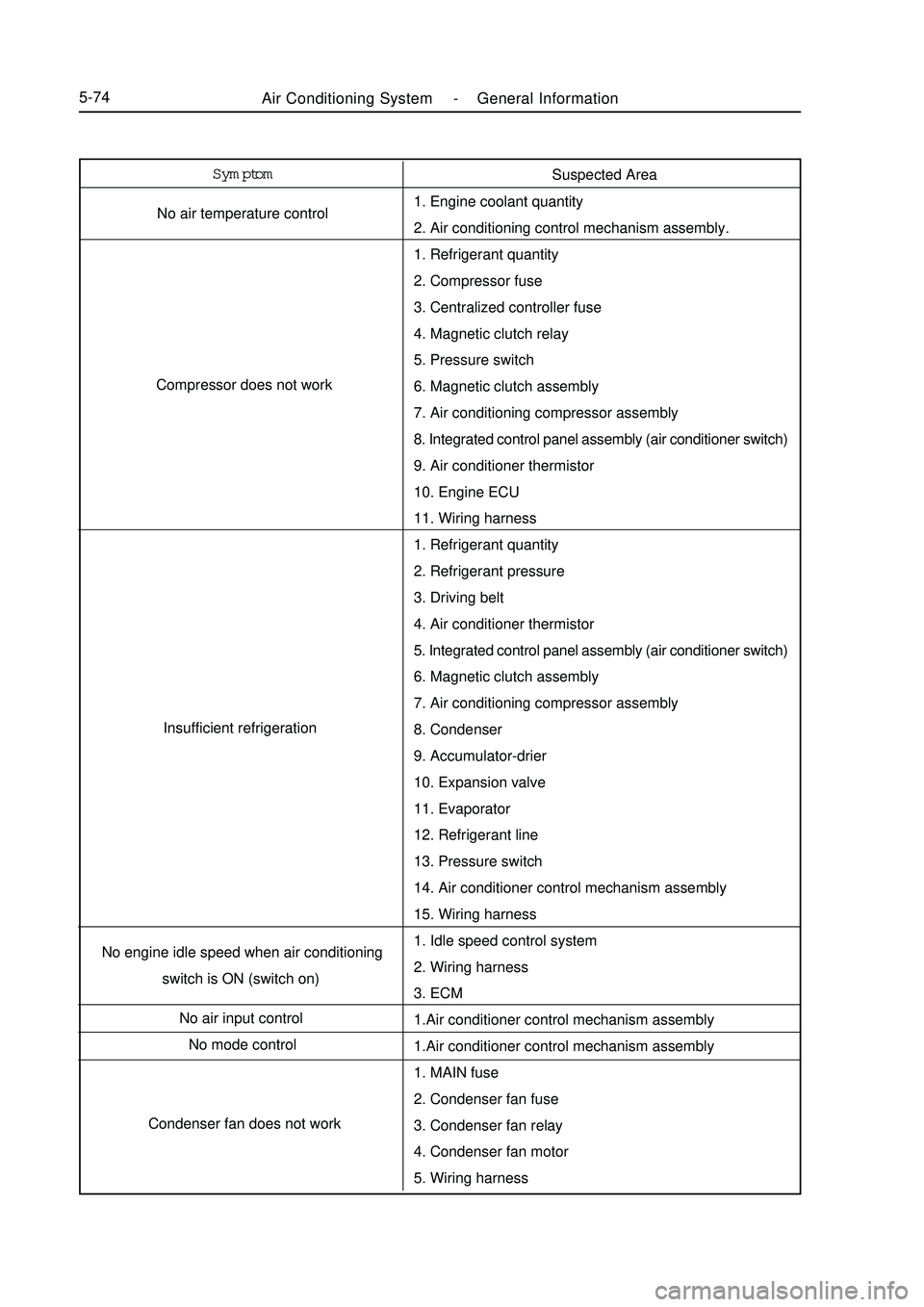
Air Conditioning System -General Information5-74Symptom
No air temperature control
Compressor does not work
Insufficient refrigeration
No engine idle speed when air conditioning
switch is ON (switch on)
No air input control
No mode control
Condenser fan does not workSuspected Area
1. Engine coolant quantity
2. Air conditioning control mechanism assembly.
1. Refrigerant quantity
2. Compressor fuse
3. Centralized controller fuse
4. Magnetic clutch relay
5. Pressure switch
6. Magnetic clutch assembly
7. Air conditioning compressor assembly
8. Integrated control panel assembly (air conditioner switch)
9. Air conditioner thermistor
10. Engine ECU
11. Wiring harness
1. Refrigerant quantity
2. Refrigerant pressure
3. Driving belt
4. Air conditioner thermistor
5. Integrated control panel assembly (air conditioner switch)
6. Magnetic clutch assembly
7. Air conditioning compressor assembly
8. Condenser
9. Accumulator-drier
10. Expansion valve
11. Evaporator
12. Refrigerant line
13. Pressure switch
14. Air conditioner control mechanism assembly
15. Wiring harness
1. Idle speed control system
2. Wiring harness
3. ECM
1.Air conditioner control mechanism assembly
1.Air conditioner control mechanism assembly
1. MAIN fuse
2. Condenser fan fuse
3. Condenser fan relay
4. Condenser fan motor
5. Wiring harness
Page 276 of 416

5-897. Disconnect engine ECU
(1) Remove 3 bolts.
(2) Carefully disconnect the wire harness.
8. Remove A/C head unit assembly.
(1) Remove the clip attaching the console wire harness on the
A/C head unit body.
(2) Disconnect 3 connectors.
(3) Remove 2 bolts and 5 nuts, remove the A/C head unit
assembly
9. Remove heater core
(1) Loosen two clips, remove the air inlet case assembly.
(2) Remove the screw, clamp and heater core.
10. Remove A/C wire harness
disconnect the connector, remove the A/C wire harness.2 clipsAir Conditioning System -Heater, Ventilation and Air Conditioning
Page 286 of 416

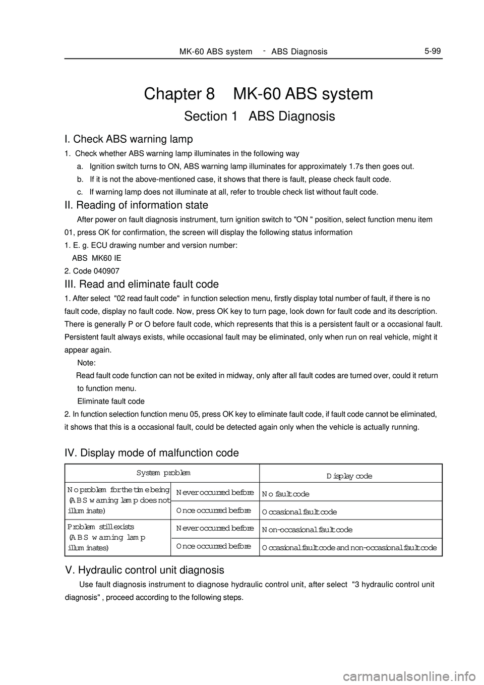
System problem
No problem for the time being
(ABS warning lamp does not
illuminate)Never occurred before
Once occurred before
Never occurred before
Once occurred before Problem still exists
(ABS warning lamp
illuminates)Chapter 8 MK-60 ABS systemSection 1 ABS DiagnosisV. Hydraulic control unit diagnosis Use fault diagnosis instrument to diagnose hydraulic control unit, after select "3 hydraulic control unit
diagnosis" , proceed according to the following steps.MK-60 ABS system -
ABS Diagnosis5-99I. Check ABS warning lamp1. Check whether ABS warning lamp illuminates in the following way
a. Ignition switch turns to ON, ABS warning lamp illuminates for approximately 1.7s then goes out.
b. If it is not the above-mentioned case, it shows that there is fault, please check fault code.
c. If warning lamp does not illuminate at all, refer to trouble check list without fault code.II. Reading of information state After power on fault diagnosis instrument, turn ignition switch to "ON " position, select function menu item
01, press OK for confirmation, the screen will display the following status information
1. E. g. ECU drawing number and version number:
ABS MK60 IE
2. Code 040907III. Read and eliminate fault code1. After select "02 read fault code" in function selection menu, firstly display total number of fault, if there is no
fault code, display no fault code. Now, press OK key to turn page, look down for fault code and its description.
There is generally P or O before fault code, which represents that this is a persistent fault or a occasional fault.
Persistent fault always exists, while occasional fault may be eliminated, only when run on real vehicle, might it
appear again.
Note:
Read fault code function can not be exited in midway, only after all fault codes are turned over, could it return
to function menu.
Eliminate fault code
2. In function selection function menu 05, press OK key to eliminate fault code, if fault code cannot be eliminated,
it shows that this is a occasional fault, could be detected again only when the vehicle is actually running.IV. Display mode of malfunction codeDisplay code
No fault code
Occasional fault code
Non-occasional fault code
Occasional fault code and non-occasional fault code
Page 289 of 416

3317
247
1632
17 6 5 4 3 2 1ABS ECU socket pin distribution (wiring harness end)
(1) ABS ECU socket (view of leading-out terminal) (3) Diagnosis connector (2) Trouble light driver module46
31
15MK-60 ABS system -ABS Diagnosis5-102