oil GEELY MK 2008 Owner's Manual
[x] Cancel search | Manufacturer: GEELY, Model Year: 2008, Model line: MK, Model: GEELY MK 2008Pages: 416, PDF Size: 25.19 MB
Page 42 of 416
Part III EngineChpater 1 Engine AssemblyInformation about engine accessories in MK-1 Car Maintenance Manual deals with only that concerned with a
complete car. Please refer to separated Maintenance Manual for information about the engine body. Engines
concerned are MR479Q, MR479QA and MR481QA.Section 1 Engine Inspection1. Check the engine oil
(1) Check the oil level.
(2) Start the engine, and reach warm-up temperature.
(3) Shut the engine down, wait for 3-5min, and check the oil level.
(4) Check whether the oil level is in within the range marked by the scale; if it is lower than the limit (mark
L), fill oil to mark F.
(5) Keep the oil clean without any coolant or petrol mixed in and with appropriate viscosity.
2. Change oil.
(1) Start the engine. When normal temperature is reached, shut down the engine.
(2) Open the oil cap, remove the oil drain plug, and drain the oil.
(3) Tighten the oil drain plug to a specified torque 54N.m.
(4) Fill fresh oil into the crank case with oil quantity 2.8L in case of the filter not changed, 3.0L in case of the
filter changed and 3.5L in case of the dry filter.
(5) Fit on the oil filling cap.
(6) Start the engine.
(7) Shut down the engine and check the oil quantity, and fill oil to the mark F on the oil scale if necessary.
3. Replace the oil filter.
(1) Remove the oil filter.
(2) Before mounting the oil filter, apply a small quantity of engine oil to the O-ring of the new oil filter.
(3) Tight the oil filter to a specified torque (12.7N.m).
(4) Start the engine, and check whether there is any leakage
(5) Shut down the engine, check the oil quantity and fill as required.
4. Oil selection
Oil over PAI SG grade is preferred.
SAE10W-30 or SAE10W-40 is preferred, and ASE5W-30 is used in cold region in the winter.
Note: For the best effect and the greatest safety, it is advisable to use the following lubrication oil.
a. Meet the requirements of API level.
b. Select proper SAE viscosity rating within expected ambient temperature.
The lubrication oil that can not meet the requirements of SAE viscosity and API label at the same time is not
allowed.
5. Check the coolant.
(1) After the engine is cooled down, remove the radiator cover.EngineEngine Assembly3-1 -
Page 45 of 416

12. Check the compressing pressure (see Figure 1-4).
(1) Warm up and switch off the engine.
(2) Remove the secondary wire.
(3) Remove the spark plug.
(4) Check the compressing pressure in the cylinder.
a.Insert the pressure gauge into the spark plug bore.
b. Throttle widely opens.
c. Rotate the engine crankshaft and measure the compressing
pressure (see Table 2).Figure 1-4Table 2Cylinder compressing pressure (KPa)Pressure difference range of cylinders of this model (KPa)Minimum compressing pressure (KPa)MR479Q MR479QA MR481QA
1250 1320 1360
100
980
Attention:
The electric quantity in the battery should be always enough, and the engine speed should be not less than
250r/min.
Check the compressing pressure in other cylinders in the same way.
Measure as soon as possible.
(5) If the compressing pressure in more than one cylinder is relatively low, fill a bit engine oil to the cylinder
through the spark plug bore, and repeat step a to c to check.
Tip:
If the compressing pressure is increased after the oil is filled, the piston ring or the cylinder may be worn or
damaged.
If the pressure is still low, the valve may be jammed or badly sealed, or the washer may be leaked.
13. Check CO/HC.
(1) Start the engine.
(2) Keep the engine running at a speed of 2500 r/min for about 180s.
(3) During idling, insert the test bar of CO/HC instrument into the exhaust pipe about 40cm depth at least.
(4) Check the concentration of emission of CO/HC at idle speed and at a speed of 2500 r/min respectively.
Tip:
Measure within 3 minutes.
Test the concentration of emission and lambda value of CO/HC at idle speed and at a speed of 2500 r/min
respectively according to GB18352.3-2005 standard.
(5) If the concentration of CO/HC is not up to standard, carry out fault diagnosis by following the steps below.
(1) Check oxygen sensor.
(2) Refer to Table 3 to find possible causes, check and repair.Engine AssemblyEngine Inspection3-4 -
Page 46 of 416

Table 3Section 2 Removal of the Engine Assembly from the Vehicle1. Avoid petrol overflowing (Disconnect from the fuel tank).
2. Remove the front wheel.Figure 1-5Engine AssemblyRemoval of the Engine Assembly from the Vehicle3-5CO
Normal
Low
HighHC
High
High
HighProblems
Bad idle speed
Bad idle speed
(HC reading fluctuates)
Bad idle speed
(Black smoke exhausts)Causes
1. Ignition fault:
Incorrect ignition timing;
Dirt, short circuit, or incorrect spark plug gap.
2. Incorrect valve gap.
3. Suction and exhaust valve leak.
4. Cylinder leaks.
1. Vacuum leaks.
PCV pipe . manifold;
Idle speed control valve;
Brake booster pipeline.
2. Spark lacks since the mixed gas is too thin.
1. Air filter is blocked.
2. PCV valve is blocked.
3. EFI system fails.
ECU fails.
Pressure regulator of fuel oil is out of order.
Water temperature sensor does not work.
Suction pressure/temperature sensor fails.
Injector fails.
The throttle position sensor fails.3. Discharge the coolant completely.
4. Remove the air filter assembly with hose (see Figure 1-5).
(1) Disconnect the joint of the temperature sensor and the wire
plug.
(2) Disconnect the vent duct from the hose of the air filter.
(3) Release the wire clip bolt on the air filter.
(4) Disconnect the hose of the air filter from the throttle body.
(5) Remove 3 bolts and the air filter assemblies.
5. Remove the battery.
6. Remove the fuel pipe sub-assembly.
7. Disconnect the water pipe; disconnect the water outlet pipe of the
heater from the air conditioner pipe.
8. Release the nut and remove the accelerator control cable. -
Page 47 of 416
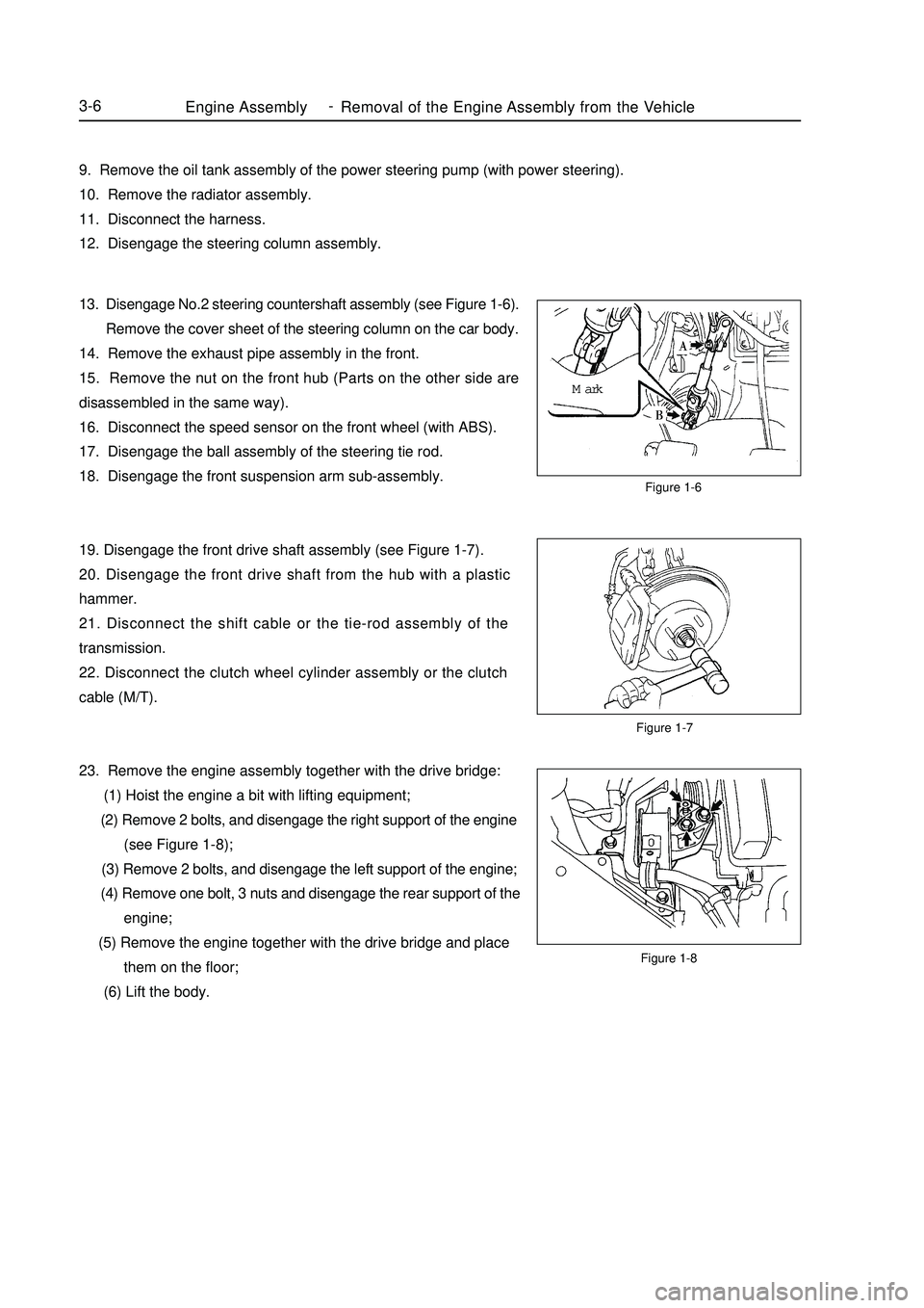
Figure 1-7Figure 1-6
Figure 1-8Engine AssemblyRemoval of the Engine Assembly from the Vehicle3-69. Remove the oil tank assembly of the power steering pump (with power steering).
10. Remove the radiator assembly.
11. Disconnect the harness.
12. Disengage the steering column assembly.
13. Disengage No.2 steering countershaft assembly (see Figure 1-6).
Remove the cover sheet of the steering column on the car body.
14. Remove the exhaust pipe assembly in the front.
15. Remove the nut on the front hub (Parts on the other side are
disassembled in the same way).
16. Disconnect the speed sensor on the front wheel (with ABS).
17. Disengage the ball assembly of the steering tie rod.
18. Disengage the front suspension arm sub-assembly.
19. Disengage the front drive shaft assembly (see Figure 1-7).
20. Disengage the front drive shaft from the hub with a plastic
hammer.
21. Disconnect the shift cable or the tie-rod assembly of the
transmission.
22. Disconnect the clutch wheel cylinder assembly or the clutch
cable (M/T).
23. Remove the engine assembly together with the drive bridge:
(1) Hoist the engine a bit with lifting equipment;
(2) Remove 2 bolts, and disengage the right support of the engine
(see Figure 1-8);
(3) Remove 2 bolts, and disengage the left support of the engine;
(4) Remove one bolt, 3 nuts and disengage the rear support of the
engine;
(5) Remove the engine together with the drive bridge and place
them on the floor;
(6) Lift the body.Mark -
Page 49 of 416

Chapter 2 Engine MechanicalSection 1 Engine ComponentsComponent ViewFigure 2-1Engine MechanicalEngine Components3-8Upside of radiator support
Engine cover lock assembly
Starter assembly
Output pipe of oil cooler
Input pipe of oil coolerTransmission control cable assembly Fuel oil sub-assembly Accelerator control cable assemble
Water inlet pipe of heater
Water outlet pipe of heaterTransmission control cable assemblySuitable for 1.5L/1.6L(Tight coupling)Suitable for 1.3L/1.5L(Non-tight coupling) Radiator assemblyAir filter assembly with hose
Clutch release assembly
Water inlet pipe of radiator
Water outlet pipe of radiator
Battery -
Page 51 of 416
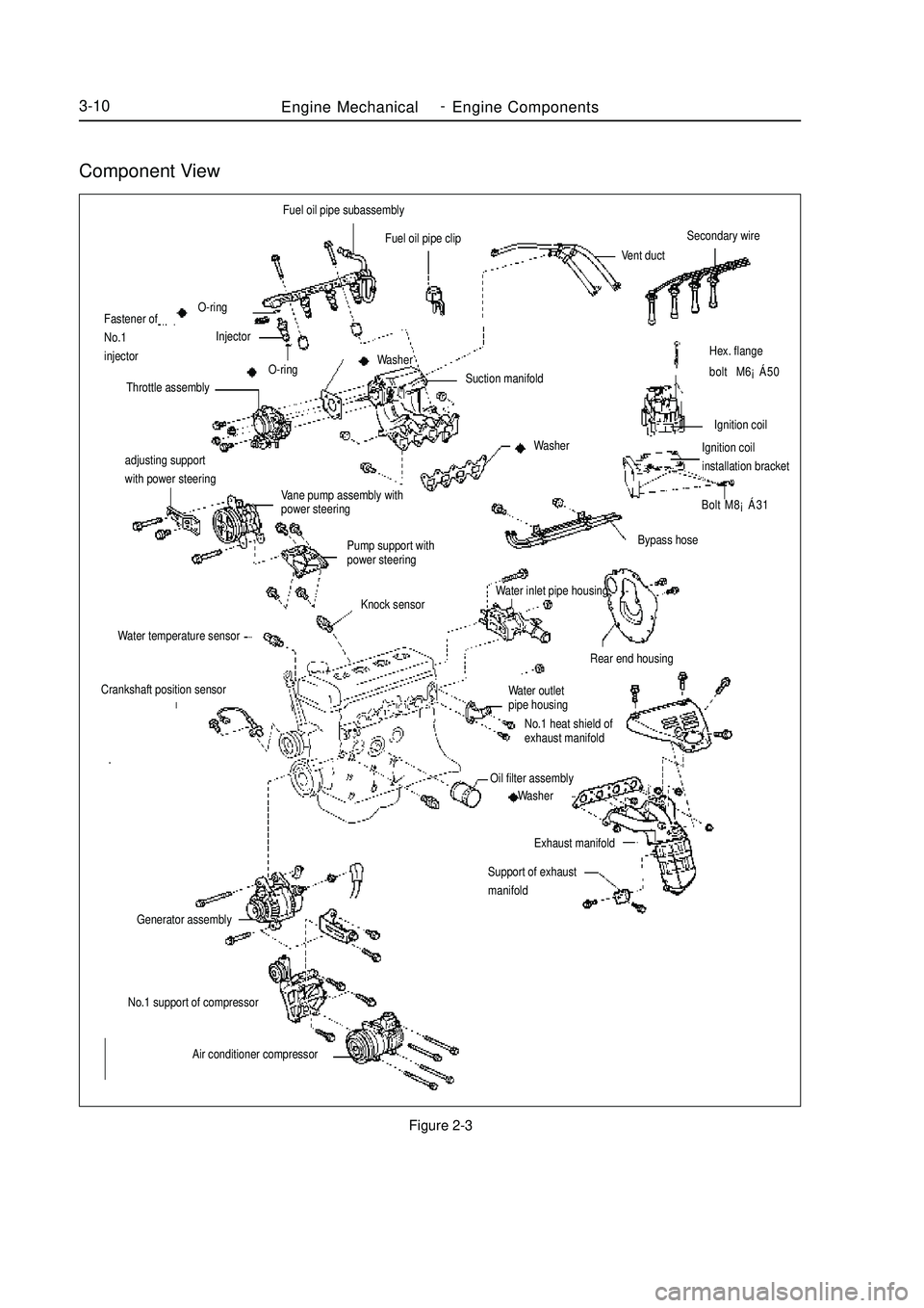
Component ViewFigure 2-3Engine MechanicalEngine Components3-10adjusting support
with power steering
Vane pump assembly with
power steering
Pump support with
power steeringHex. flange
bolt M6¡Á50
Ignition coil
Ignition coilinstallation bracket
Bolt M8¡Á31Fuel oil pipe subassembly
Fuel oil pipe clip
Vent ductSecondary wireBypass hose
Rear end housingWater outlet
pipe housing
No.1 heat shield of
exhaust manifoldOil filter assembly
Washer
Exhaust manifold
Support of exhaust
manifoldO-ring
Fastener of
No.1
injectorInjector
O-ring
Throttle assemblySuction manifold Washer
WasherKnock sensor
Water temperature sensorCrankshaft position sensorGenerator assemblyNo.1 support of compressor
Air conditioner compressorWater inlet pipe housing -
Page 56 of 416
Chapter 3 Fuel SystemSection 1 Check Fuel System PressureOn-board inspection
1. Check the operation of the fuel pump.
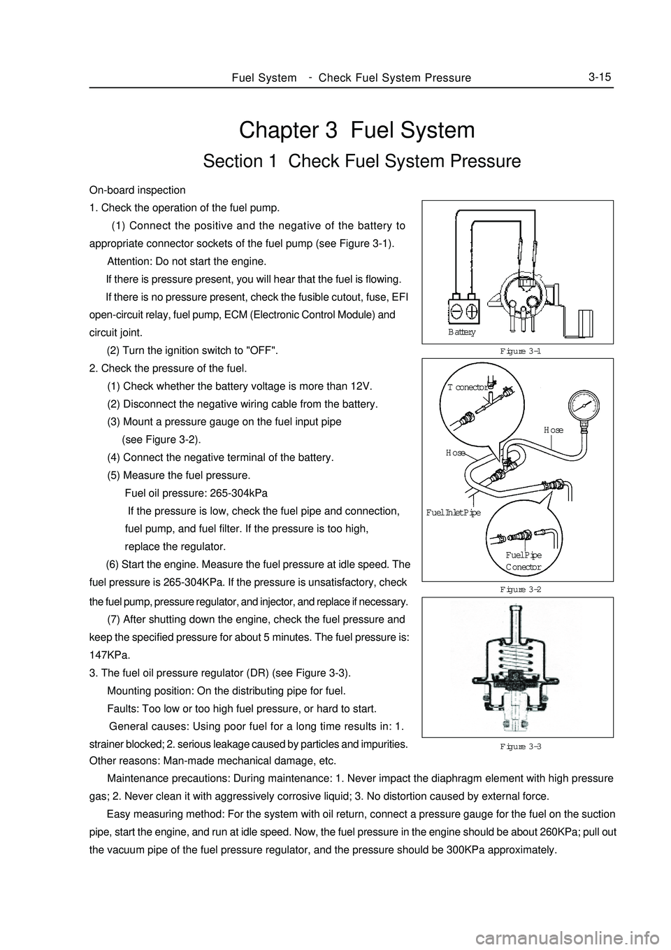
(1) Connect the positive and the negative of the battery to
appropriate connector sockets of the fuel pump (see Figure 3-1).
Attention: Do not start the engine.
If there is pressure present, you will hear that the fuel is flowing.
If there is no pressure present, check the fusible cutout, fuse, EFI
open-circuit relay, fuel pump, ECM (Electronic Control Module) and
circuit joint.
(2) Turn the ignition switch to "OFF".
2. Check the pressure of the fuel.
(1) Check whether the battery voltage is more than 12V.
(2) Disconnect the negative wiring cable from the battery.
(3) Mount a pressure gauge on the fuel input pipe
(see Figure 3-2).
(4) Connect the negative terminal of the battery.
(5) Measure the fuel pressure.
Fuel oil pressure: 265-304kPa
If the pressure is low, check the fuel pipe and connection,
fuel pump, and fuel filter. If the pressure is too high,
replace the regulator.
(6) Start the engine. Measure the fuel pressure at idle speed. The
fuel pressure is 265-304KPa. If the pressure is unsatisfactory, checkFigure 3-1
Figure 3-3 Figure 3-2Fuel SystemCheck Fuel System Pressure3-15the fuel pump, pressure regulator, and injector, and replace if necessary.
(7) After shutting down the engine, check the fuel pressure and
keep the specified pressure for about 5 minutes. The fuel pressure is:
147KPa.
3. The fuel oil pressure regulator (DR) (see Figure 3-3).
Mounting position: On the distributing pipe for fuel.
Faults: Too low or too high fuel pressure, or hard to start.
General causes: Using poor fuel for a long time results in: 1.
strainer blocked; 2. serious leakage caused by particles and impurities.
Other reasons: Man-made mechanical damage, etc.
Maintenance precautions: During maintenance: 1. Never impact the diaphragm element with high pressure
gas; 2. Never clean it with aggressively corrosive liquid; 3. No distortion caused by external force.
Easy measuring method: For the system with oil return, connect a pressure gauge for the fuel on the suction
pipe, start the engine, and run at idle speed. Now, the fuel pressure in the engine should be about 260KPa; pull out
the vacuum pipe of the fuel pressure regulator, and the pressure should be 300KPa approximately.Battery
T conector
Hose
Hose
Fuel Inlet Pipe
Fuel Pipe
Conector -
Page 57 of 416
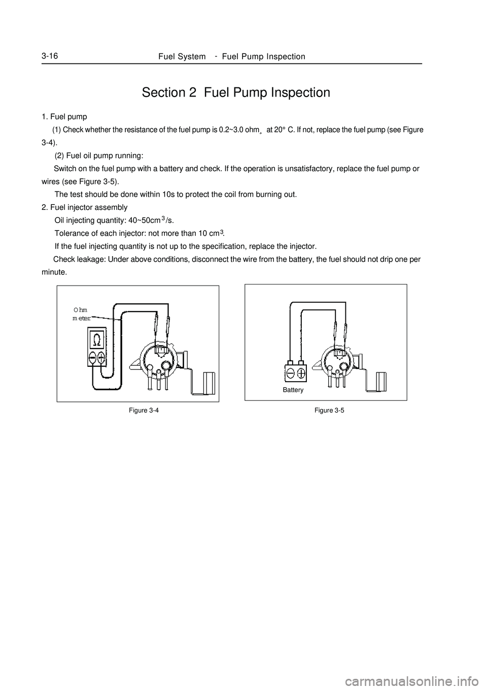
Section 2 Fuel Pump Inspection1. Fuel pump (1) Check whether the resistance of the fuel pump is 0.2~3.0 ohm¸ at 20°C. If not, replace the fuel pump (see Figure3-4).
(2) Fuel oil pump running:
Switch on the fuel pump with a battery and check. If the operation is unsatisfactory, replace the fuel pump or
wires (see Figure 3-5).
The test should be done within 10s to protect the coil from burning out.
2. Fuel injector assembly
Oil injecting quantity: 40~50cm3/s.
Tolerance of each injector: not more than 10 cm3.
If the fuel injecting quantity is not up to the specification, replace the injector.
Check leakage: Under above conditions, disconnect the wire from the battery, the fuel should not drip one per
minute.Figure 3-4 Figure 3-5BatteryOhm
meterFuel SystemFuel Pump Inspection3-16 -
Page 58 of 416
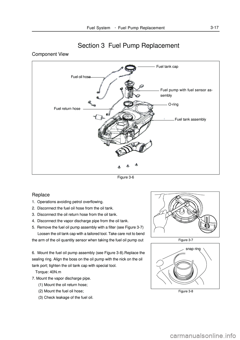
Section 3 Fuel Pump ReplacementComponent ViewFigure 3-6Replace1. Operations avoiding petrol overflowing.
2. Disconnect the fuel oil hose from the oil tank.
3. Disconnect the oil return hose from the oil tank.
4. Disconnect the vapor discharge pipe from the oil tank.
5. Remove the fuel oil pump assembly with a filter (see Figure 3-7)
Loosen the oil tank cap with a tailored tool. Take care not to bend
the arm of the oil quantity sensor when taking the fuel oil pump out
6. Mount the fuel oil pump assembly (see Figure 3-8).Replace the
sealing ring. Align the boss on the oil pump with the nick on the oil
tank port; tighten the oil tank cap with special tool.
Torque: 40N.m
7. Mount the vapor discharge pipe.
(1) Mount the oil return hose;
(2) Mount the fuel oil hose;
(3) Check leakage of the fuel oil.Figure 3-7
Figure 3-8Fuel SystemFuel Pump Replacement3-17Fuel tank cap
Fuel pump with fuel sensor as-
sembly
O-ring
Fuel tank assembly Fuel return hoseFuel oil hose
snap ring -
Page 60 of 416
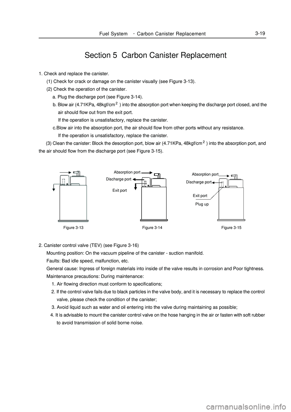
Section 5 Carbon Canister Replacement1. Check and replace the canister.
(1) Check for crack or damage on the canister visually (see Figure 3-13).
(2) Check the operation of the canister.
a. Plug the discharge port (see Figure 3-14).
b. Blow air (4.71KPa, 48kgf/cm2) into the absorption port when keeping the discharge port closed, and the
air should flow out from the exit port.
If the operation is unsatisfactory, replace the canister.
c.Blow air into the absorption port, the air should flow from other ports without any resistance.
If the operation is unsatisfactory, replace the canister.
(3) Clean the canister: Block the desorption port, blow air (4.71KPa, 48kgf/cm2) into the absorption port, and
the air should flow from the discharge port (see Figure 3-15).Fuel SystemCarbon Canister Replacement3-192. Canister control valve (TEV) (see Figure 3-16)
Mounting position: On the vacuum pipeline of the canister - suction manifold.
Faults: Bad idle speed, malfunction, etc.
General cause: Ingress of foreign materials into inside of the valve results in corrosion and Poor tightness.
Maintenance precautions: During maintenance:
1. Air flowing direction must conform to specifications;
2. If the control valve fails due to black particles in the valve body, and it is necessary to replace the control
valve, please check the condition of the canister;
3. Avoid liquid such as water and oil entering into the valve during maintaining as possible;
4. It is advisable to mount the canister control valve on the hose hanging in the air or fasten with soft rubber
to avoid transmission of solid borne noise.Figure 3-13Figure 3-15 Absorption port
Discharge port
Exit port
Plug upFigure 3-14Absorption port
Discharge port
Exit port -