parking brake GEELY MK 2008 Owner's Manual
[x] Cancel search | Manufacturer: GEELY, Model Year: 2008, Model line: MK, Model: GEELY MK 2008Pages: 416, PDF Size: 25.19 MB
Page 181 of 416

Brake System -Rear Brake Drum4-104 (2) As shown in the figure, install the parking brake left post.
27. Install the front brake shoe.
(1) Install the return spring on the front brake shoe.
(2) Install the front brake shoe, pin, set spring and set spring cap
with a special tool.
28. Connect the parking brake shoe left post.
Connect the extension spring to the front/rear brake shoe with a
special tool.
Note:
Be careful not to damage to the dust shield of the brake wheel
cylinder.
29. Check the installation of the brake drum.
(1) Check all parts whether they are installed properly.Braking Plate
parking brake left post
Page 182 of 416
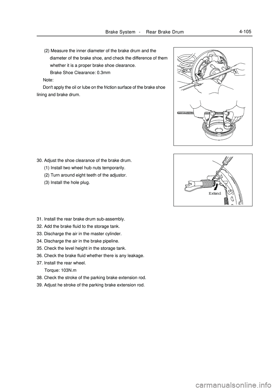
Brake System -Rear Brake Drum4-105 (2) Measure the inner diameter of the brake drum and the
diameter of the brake shoe, and check the difference of them
whether it is a proper brake shoe clearance.
Brake Shoe Clearance: 0.3mm
Note:
Don't apply the oil or lube on the friction surface of the brake shoe
lining and brake drum.
30. Adjust the shoe clearance of the brake drum.
(1) Install two wheel hub nuts temporarily.
(2) Turn around eight teeth of the adjustor.
(3) Install the hole plug.
31. Install the rear brake drum sub-assembly.
32. Add the brake fluid to the storage tank.
33. Discharge the air in the master cylinder.
34. Discharge the air in the brake pipeline.
35. Check the level height in the storage tank.
36. Check the brake fluid whether there is any leakage.
37. Install the rear wheel.
Torque: 103N.m
38. Check the stroke of the parking brake extension rod.
39. Adjust he stroke of the parking brake extension rod.Extend
Page 183 of 416
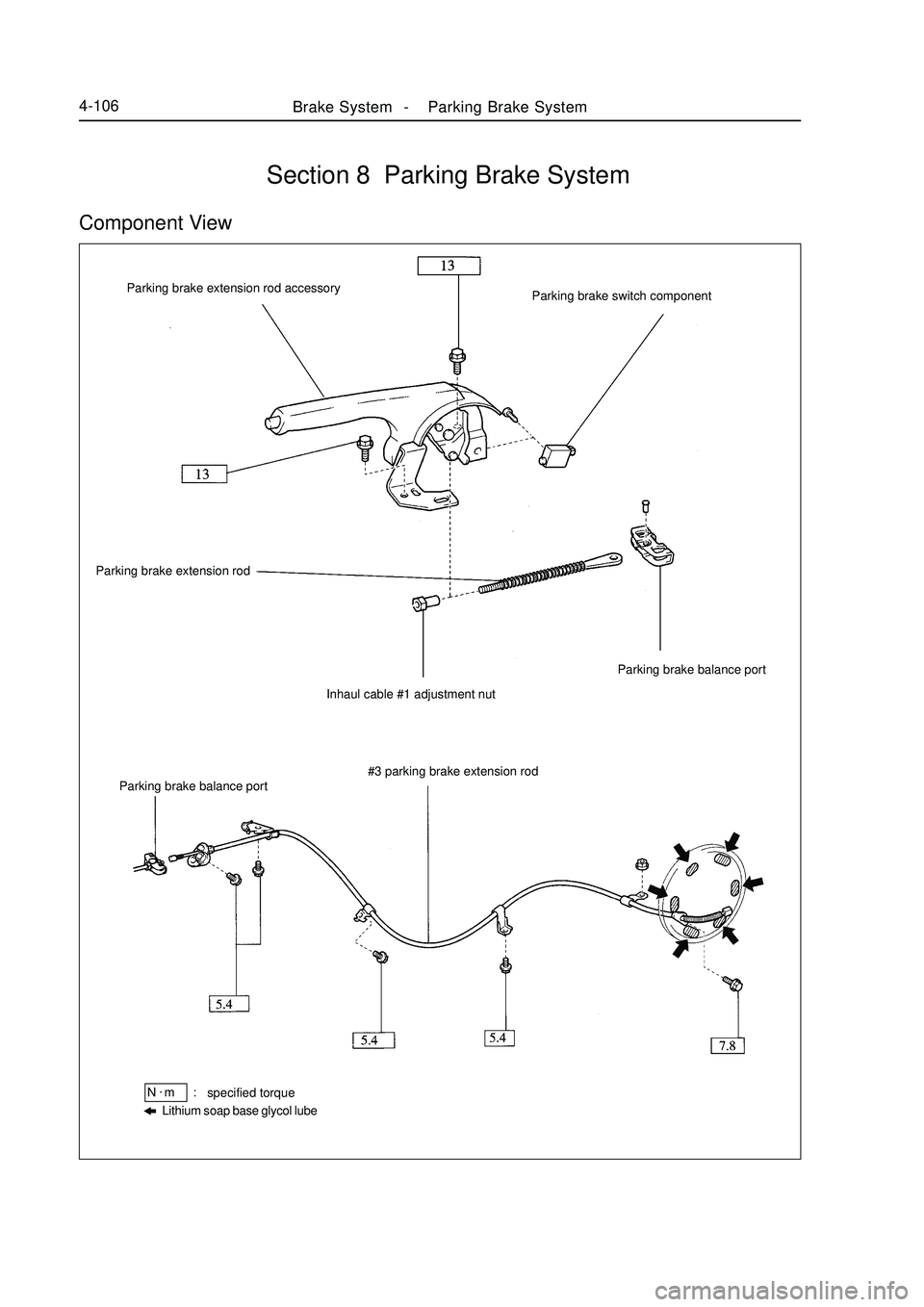
Brake System -Parking Brake System4-106Section 8 Parking Brake SystemComponent View#3 parking brake extension rod
Lithium soap base glycol lubespecified torqueN.
m :Parking brake balance port Parking brake extension rod
Inhaul cable #1 adjustment nutParking brake balance port Parking brake extension rod accessory
Parking brake switch component
Page 184 of 416
Brake System -Parking Brake System4-107Adjustment1. Remove the rear wheel.
2. Adjust the clearance of the brake shoe.
3. Install the rear wheel.
Torque: 103N.m
4. Check the stroke of the parking brake extension rod.
Pull the parking brake extension rod, and count the number of sound.
Parking Brake Extension Rod Stroke: Pull with 196N force till 6-9 clicks.
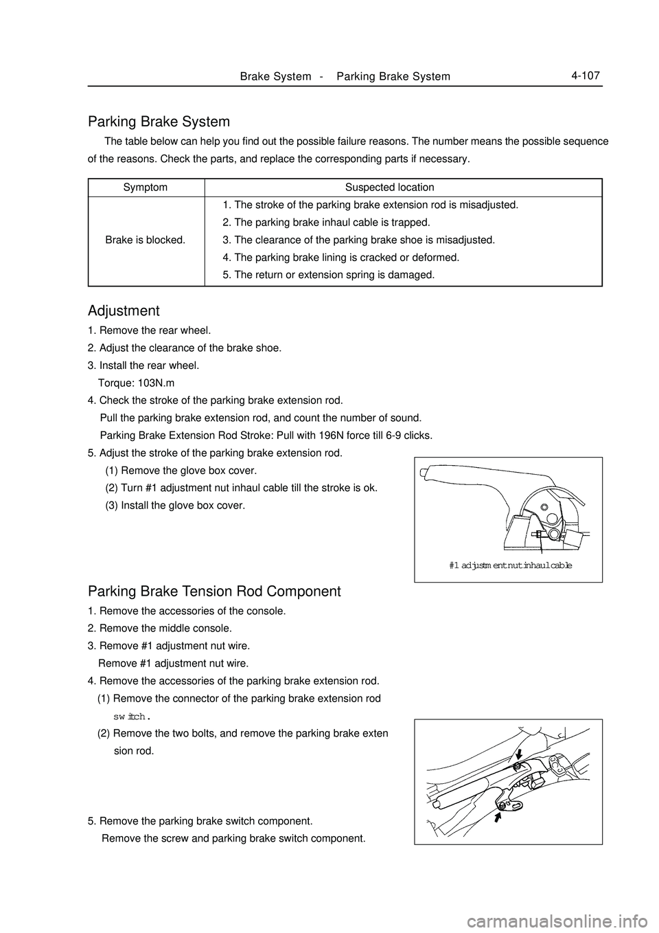
5. Adjust the stroke of the parking brake extension rod.
(1) Remove the glove box cover.
(2) Turn #1 adjustment nut inhaul cable till the stroke is ok.
(3) Install the glove box cover.Parking Brake System The table below can help you find out the possible failure reasons. The number means the possible sequence
of the reasons. Check the parts, and replace the corresponding parts if necessary.Parking Brake Tension Rod Component1. Remove the accessories of the console.
2. Remove the middle console.
3. Remove #1 adjustment nut wire.
Remove #1 adjustment nut wire.
4. Remove the accessories of the parking brake extension rod.
(1) Remove the connector of the parking brake extension rod
switch.
(2) Remove the two bolts, and remove the parking brake exten
sion rod.
5. Remove the parking brake switch component.
Remove the screw and parking brake switch component.Suspected location
1. The stroke of the parking brake extension rod is misadjusted.
2. The parking brake inhaul cable is trapped.
3. The clearance of the parking brake shoe is misadjusted.
4. The parking brake lining is cracked or deformed.
5. The return or extension spring is damaged.Symptom
Brake is blocked.#1 adjustment nut inhaul cable
Page 185 of 416
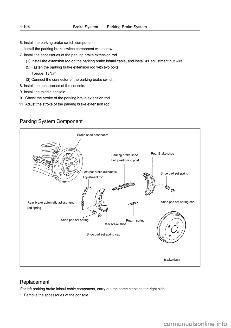
Brake System -Parking Brake System4-108Brake shoe baseboard
Parking brake shoe
Left positioning postRear Brake shoe
Shoe pad set spring cap
Rear brake shoe
Shoe pad set spring cap Shoe pad set springParking System Component
Replacement For left parking brake inhaul cable component, carry out the same steps as the right side.
1. Remove the accessories of the console. 6. Install the parking brake switch component.
Install the parking brake switch component with screw.
7. Install the accessories of the parking brake extension rod.
(1) Install the extension rod on the parking brake inhaul cable, and install #1 adjustment nut wire.
(2) Fasten the parking brake extension rod with two bolts.
Torque: 13N.m
(3) Connect the connector of the parking brake switch.
8. Install the accessories of the console.
9. Install the middle console.
10. Check the stroke of the parking brake extension rod.
11. Adjust the stroke of the parking brake extension rod.Shoe pad set spring
Brake drum Return spring Rear brake automatic adjustment
rod springLeft rear brake automatic
Adjustment rod
Page 186 of 416
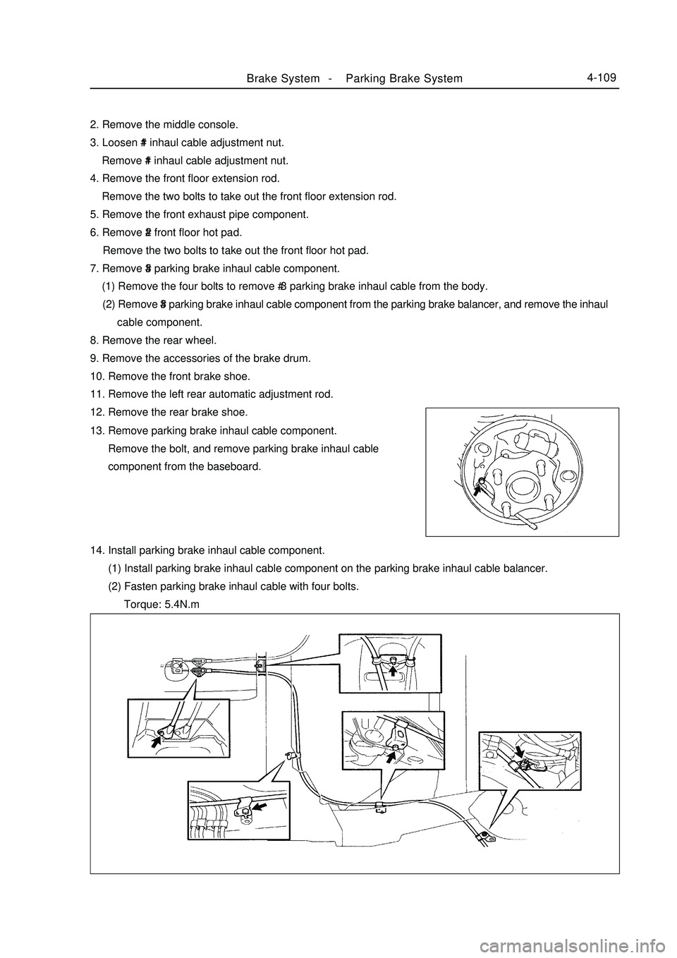
Brake System -Parking Brake System4-1092. Remove the middle console.
3. Loosen #1 inhaul cable adjustment nut.
Remove #1 inhaul cable adjustment nut.
4. Remove the front floor extension rod.
Remove the two bolts to take out the front floor extension rod.
5. Remove the front exhaust pipe component.
6. Remove #2 front floor hot pad.
Remove the two bolts to take out the front floor hot pad.
7. Remove #3 parking brake inhaul cable component.
(1) Remove the four bolts to remove # 3 parking brake inhaul cable from the body.
(2) Remove #3 parking brake inhaul cable component from the parking brake balancer, and remove the inhaul
cable component.
8. Remove the rear wheel.
9. Remove the accessories of the brake drum.
10. Remove the front brake shoe.
11. Remove the left rear automatic adjustment rod.
12. Remove the rear brake shoe.
13. Remove parking brake inhaul cable component.
Remove the bolt, and remove parking brake inhaul cable
component from the baseboard.
14. Install parking brake inhaul cable component.
(1) Install parking brake inhaul cable component on the parking brake inhaul cable balancer.
(2) Fasten parking brake inhaul cable with four bolts.
Torque: 5.4N.m
Page 187 of 416
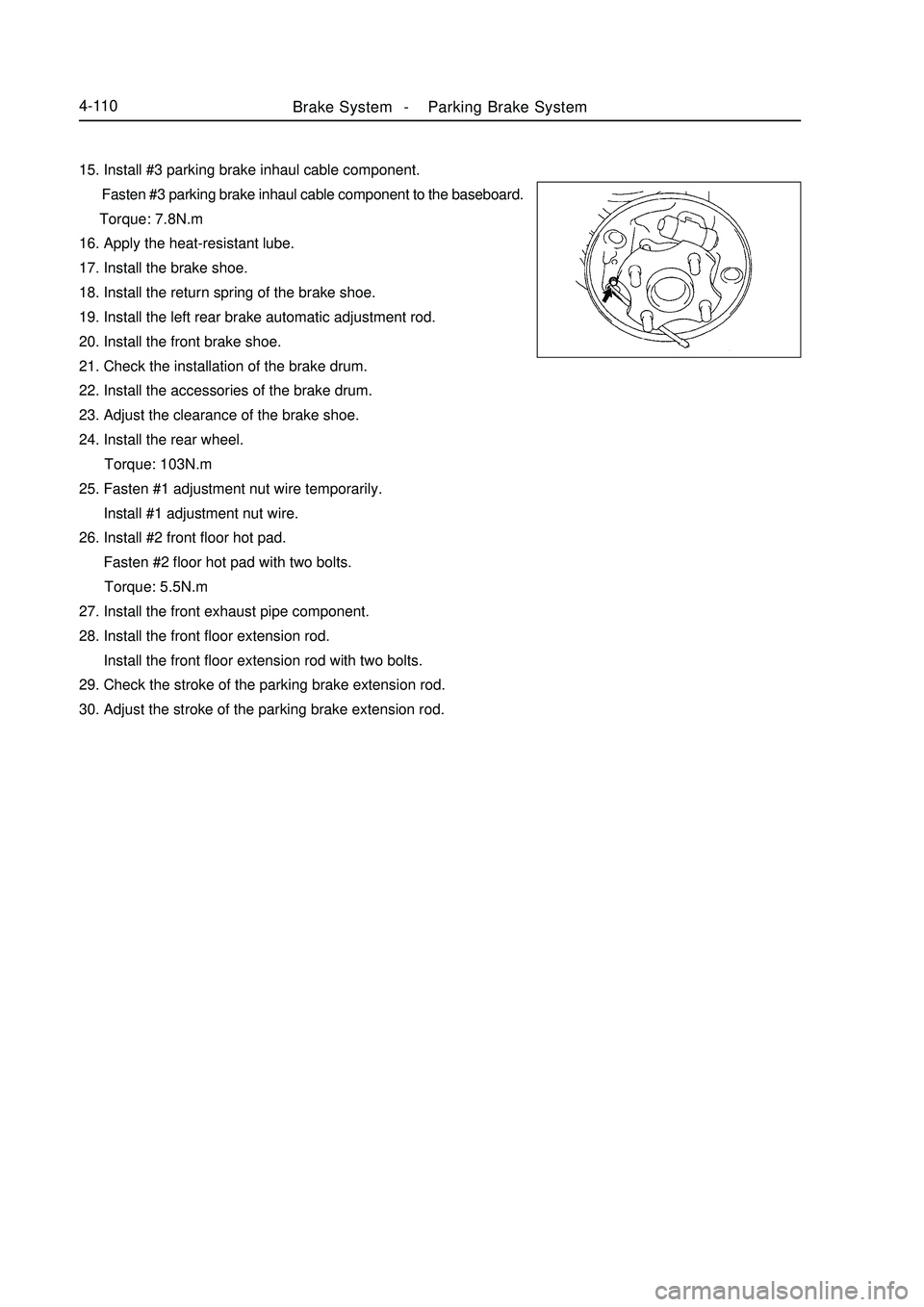
Brake System -Parking Brake System4-11015. Install #3 parking brake inhaul cable component.
Fasten #3 parking brake inhaul cable component to the baseboard.
Torque: 7.8N.m
16. Apply the heat-resistant lube.
17. Install the brake shoe.
18. Install the return spring of the brake shoe.
19. Install the left rear brake automatic adjustment rod.
20. Install the front brake shoe.
21. Check the installation of the brake drum.
22. Install the accessories of the brake drum.
23. Adjust the clearance of the brake shoe.
24. Install the rear wheel.
Torque: 103N.m
25. Fasten #1 adjustment nut wire temporarily.
Install #1 adjustment nut wire.
26. Install #2 front floor hot pad.
Fasten #2 floor hot pad with two bolts.
Torque: 5.5N.m
27. Install the front exhaust pipe component.
28. Install the front floor extension rod.
Install the front floor extension rod with two bolts.
29. Check the stroke of the parking brake extension rod.
30. Adjust the stroke of the parking brake extension rod.
Page 375 of 416
It is mainly used to install the pipes and accessories of the brake system and clutch system.
5. Front wall upper assembly
The front wall upper assembly includes left/right hinge base mounting plate big assembly, front wall upper
front cover big assembly, VIN number mounting plate, and front wall upper rear cover big assembly etc.
It forms a high-stiffness frame structure together with the engine compartment assembly and the front wall
lower plate assembly. It can generate strong resistant to the transverse collision and rolling deformation. It can also
separate the engine compartment form the cabin, preventing the odor entering into the cabin. Consequently, it can
isolate the noise, heat and vibration.(2) Floor Assembly The floor assembly is the base work of the main structure. It is a key component that connects various
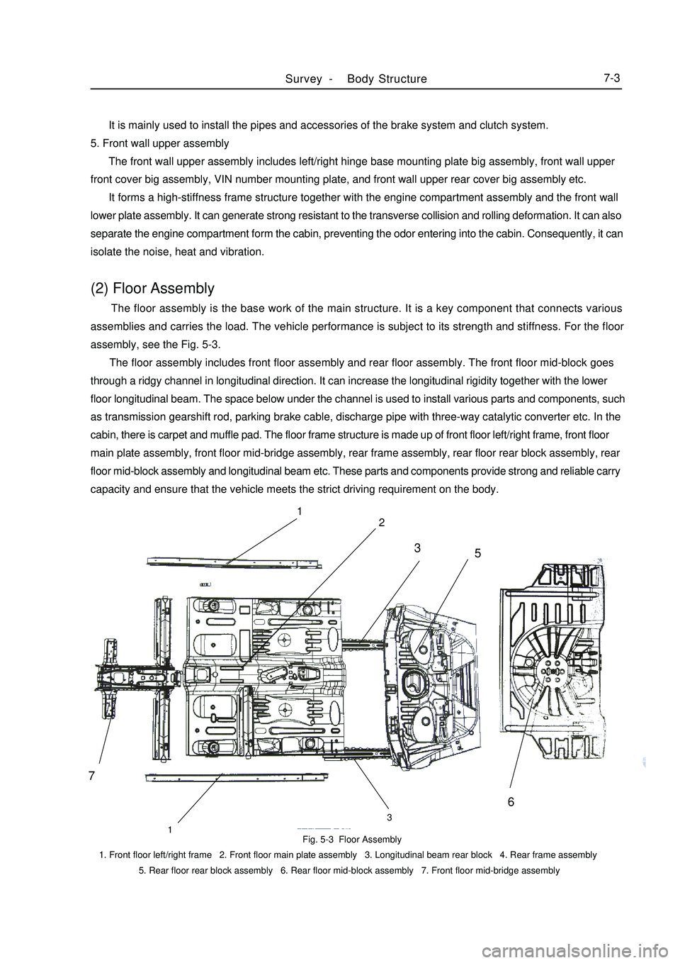
assemblies and carries the load. The vehicle performance is subject to its strength and stiffness. For the floor
assembly, see the Fig. 5-3.
The floor assembly includes front floor assembly and rear floor assembly. The front floor mid-block goes
through a ridgy channel in longitudinal direction. It can increase the longitudinal rigidity together with the lower
floor longitudinal beam. The space below under the channel is used to install various parts and components, such
as transmission gearshift rod, parking brake cable, discharge pipe with three-way catalytic converter etc. In the
cabin, there is carpet and muffle pad. The floor frame structure is made up of front floor left/right frame, front floor
main plate assembly, front floor mid-bridge assembly, rear frame assembly, rear floor rear block assembly, rear
floor mid-block assembly and longitudinal beam etc. These parts and components provide strong and reliable carry
capacity and ensure that the vehicle meets the strict driving requirement on the body.Fig. 5-3 Floor Assembly
1. Front floor left/right frame 2. Front floor main plate assembly 3. Longitudinal beam rear block 4. Rear frame assembly
5. Rear floor rear block assembly 6. Rear floor mid-block assembly 7. Front floor mid-bridge assemblySurvey -Body Structure7-371
2
133
5
6